Pressure regulator FIAT MAREA 2000 1.G User Guide
[x] Cancel search | Manufacturer: FIAT, Model Year: 2000, Model line: MAREA, Model: FIAT MAREA 2000 1.GPages: 330
Page 95 of 330
Marea- Marea Weekend 9 ™
2000 range ©) Fuel feed system
Engine
10.
Compents of injection system wiring diagram
1. Vehicle speepd
2. Rev counter
3. Engine radiator fan low speed relay
4. Radiator fan high speed activation relay
5. Potentiometer on accelerator pedal
6. Timing sensor
7. Fuel pressure sensor
8. EGR system modulator solenoid
9. Fuel pressure regulator
10. Glow plug preheating warning light on control panel
11. Injection system failure warning light
12. Air conditioning system relay
13. Coolant temperature sensor
14. Rpm sensor
15. Fuel temperature sensor
16. Diagnostic socket
17. Fiat CODE control unit
18. Four stage pressure switch
19. Injection electronic control unit
20. Pressure relief sensor
21. 7.5A fuse protecting electronic injection system ( + 15 power supply from ignition switch)
22. 7.5A fuse protecting electronic injection system ( + 30 power supply from ignition switch)
23. Main injection system relay
24. 30A fuse protecting injection system
25. Auxiliary fuel pump relay
26. Glow plug preheating control unit
27. Intake air flow and temperature sensor (debimeter)
28. Brake pedal switch
29. Clutch pedal switch
30. Ignition switch
31. Battery
32. Inertia switch
33. Auxiliary fuel pump (submerged in tank)
34. 60A fuse protecting glow plug control unit
35. Cylinder no. 1 glow plug
36. Cylinder no. 2 glow plug
37. Cylinder no. 3 glow plug
38. Cylinder no. 4 glow plug
39. Cylinder no. 1 injector
40. Cylinder no. 2 injector
41. Cylinder no. 3 injector
42. Cylinder no. 4 injector
43. Throttle valve control solenoid
44. Variable geometry turbocharger control solenoid
45. Diesel filter heater relay
Copyright by Fiat Auto 9
Page 96 of 330
Engine Marea- Marea Weekend 9 ™
Fuel feed system 2000 range @
10.
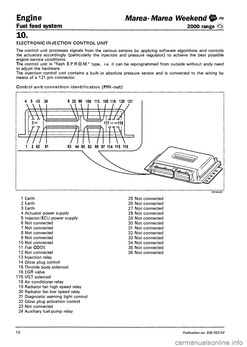
ELECTRONIC INJECTION CONTROL UNIT
The control unit processes signals from the various sensors by applying software algorithms and controls
the actuators accordingly (particularly the injectors and pressure regulator) to achieve the best possible
engine service conditions.
The control unit is "flash E.P.R.O.M." type, i.e. it can be reprogrammed from outside without andy need
to adjust the hardware.
The injection control unit contains a built-in absolute pressure sensor and is connected to the wiring by
means of a 121 pin connector.
Control unit connection identification (PIN-out)
4 5 43 24 6 25 96 106 113 105 119 120 121
1 Earth 25 Not connected
2 Earth 26 Not connected
3 Earth 27 Not connected
4 Actuator power supply 28 Not connected
5 Injector/ECU power supply 29 Not connected
6 Not connected 30 Not connected
7 Not connected 31 Not connected
8 Not connected 32 Not connected
9 Not connected 33 Not connected
10 Not connected 34 Not connected
11 Fiat CODE 35 Not connected
12 Not connected 36 Not connected
13 Injection relay
14 Glow plug control
15 Throttle body solenoid
16 EGR valve
17S VGT solenoid
18 Air conditioner relay
19 Radiator fan high speed relay
20 Radiator fan low speed relay
21 Diagnostic warning light control
22 Glow plug activation control
23 Not connected
24 Auxiliary fuel pump relay
10 Publication no. 506.763/24
Page 97 of 330
Ma tea- Ma tea Weekend !@ ™
2000 range ©
Engine
Fuel feed system
10.
37 Not connected
38 Not connected
39 Not connected
40 Not connected
41 Not connected
42 Not connected
43 Not connected
44 Not connected
45 Not connected
46 Not connected
47 Engine rpm signal output
48 Diagnostic line k
49 Vehicle speed signal input
50 Not connected
51 Activation signal from 4-stage pressure switch
52 Activation signal from 3-stage pressure switch
53 Not connected
54 Not connected
55 Not connected
56 Not connected
57 Not connected
58 Key ON signal
59 Brake switch
60 Air conditioner activation request
61 Clutch switch
62 Glow plug diagnosis
63 Not connected
64 Not connected
65 Not connected
66 Not connected
67 Not connected
68 Not connected
69 Not connected
70 Not connected
71 Not connected
72 Not connected
73 Not connected
74 Not connected
75 Not connected
76 Accelerator pedal 1 earth
77 Accelerator pedal 1 signal
78 Accelerator pedal 1 power supply
79 Accelerator pedal 2 earth
80 Accelerator pedal 2 signal
81 Accelerator pedal 2 power supply
82 Diesel temperature sensor (pin 1)
83 Diesel temperature sensor (pin 2)
84 Coolant temperature sensor (pin 1)
85 Coolant temperature sensor (pin 2)
86 Air flow meter (pin 1)
87 Not connected
88 Air flow meter (pin 3)
89 Air flow meter (pin 5)
90 Fuel pressure sensor (pin 3)
91 Fuel pressure sensor (pin 2)
92 Fuel pressure sensor (pin 1)
93 Turbo pressure sensor (pin 1)
94 Turbo pressure sensor (pin 3)
95 Turbo pressure sensor (pin 2)
96 Not connected
97 Air flow meter (pin 4)
98 Not connected
99 RPM sensor (pin 1)
100 RPM sensor (pin 2)
101 RPM sensor (pin 3)
102 RPM sensor (pin 1)
103 Timing sensor (pin 2)
104 Timing sensor (pin 3)
105 Not connected
106 Not connected
107 Not connected
108 Fuel pressure regulator
109 Fuel pressure regulator
110 Not connected
111 Heater relay control Fuel filter
112 Not connected
113 Not connected
114 Cylinder 4 injector control
115 Not connected
116 Not connected
117 Cylinder 1 and 2 injector power supply
118 Cylinder 3 and 4 injector power supply
119 Cylinder 1 injector control
120 Cylinder 2 injector control
121 Cylinder 3 injector control
Copyright by Fiat Auto 11
Page 101 of 330
Marea- Marea Weekend 9™
2000 range (§)
4F015XJ03
Engine
Fuel feed system
ijo.
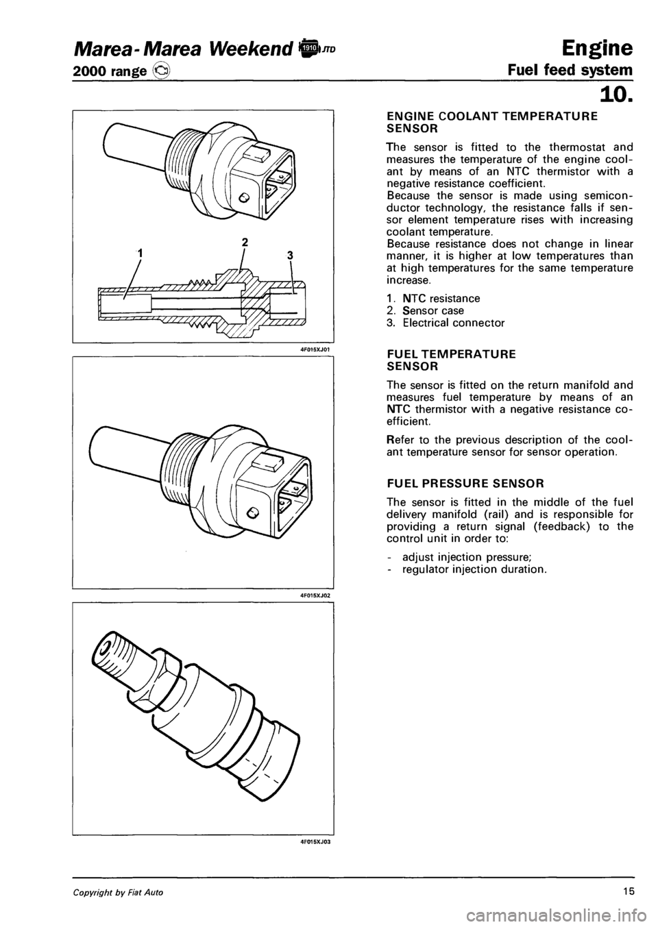
ENGINE COOLANT TEMPERATURE
SENSOR
The sensor is fitted to the thermostat and
measures the temperature of the engine cool
ant by means of an NTC thermistor with a
negative resistance coefficient.
Because the sensor is made using semicon
ductor technology, the resistance falls if sen
sor element temperature rises with increasing
coolant temperature.
Because resistance does not change in linear
manner, it is higher at low temperatures than
at high temperatures for the same temperature
increase.
1. NTC resistance
2. Sensor case
3. Electrical connector
FUEL TEMPERATURE
SENSOR
The sensor is fitted on the return manifold and
measures fuel temperature by means of an
NTC thermistor with a negative resistance co
efficient.
Refer to the previous description of the cool
ant temperature sensor for sensor operation.
FUEL PRESSURE SENSOR
The sensor is fitted in the middle of the fuel
delivery manifold (rail) and is responsible for
providing a return signal (feedback) to the
control unit in order to:
- adjust injection pressure;
- regulator injection duration.
Copyright by Fiat Auto 15
Page 104 of 330
Engine
Fuel feed system
JTD Marea- Marea Weekend 0
2000 range ©
10.
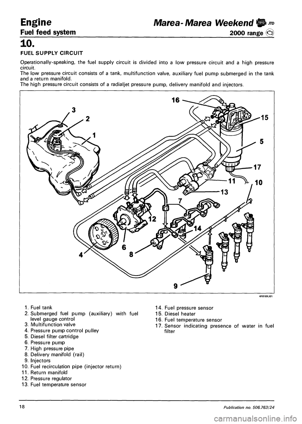
FUEL SUPPLY CIRCUIT
Operationally-speaking, the fuel supply circuit is divided into a low pressure circuit and a high pressure
circuit.
The low pressure circuit consists of a tank, multifunction valve, auxiliary fuel pump submerged in the tank
and a return manifold.
The high pressure circuit consists of a radialjet pressure pump, delivery manifold and injectors.
1. Fuel tank
2. Submerged fuel pump (auxiliary) with fuel
level gauge control
3. Multifunction valve
4. Pressure pump control pulley
5. Diesel filter cartridge
6. Pressure pump
7. High pressure pipe
8. Delivery manifold (rail)
9. Injectors
10. Fuel recirculation pipe (injector return)
11. Return manifold
12. Pressure regulator
13. Fuel temperature sensor
14. Fuel pressure sensor
15. Diesel heater
16. Fuel temperature sensor
17. Sensor indicating presence of water in fuel
filter
18 Publication no. 506.763/24
Page 106 of 330
Engine
Fuel feed system
JTD Marea-Marea Weekend @
2000 range ©
10.
7^ £3
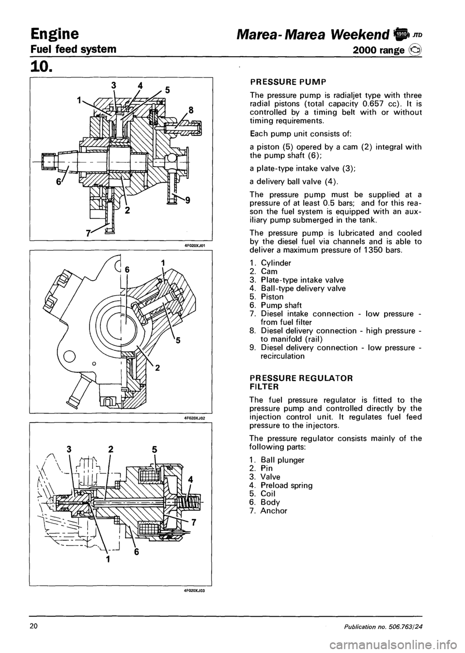
PRESSURE PUMP
The pressure pump is radialjet type with three
radial pistons (total capacity 0.657 cc). It is
controlled by a timing belt with or without
timing requirements.
Each pump unit consists of:
a piston (5) opered by a cam (2) integral with
the pump shaft (6);
a plate-type intake valve (3);
a delivery ball valve (4).
The pressure pump must be supplied at a
pressure of at least 0.5 bars; and for this rea
son the fuel system is equipped with an aux
iliary pump submerged in the tank.
The pressure pump is lubricated and cooled
by the diesel fuel via channels and is able to
deliver a maximum pressure of 1350 bars.
1.
2.
3.
4.
5.
6.
7.
8.
Cylinder
Cam
Plate-type intake valve
Ball-type delivery valve
Piston
Pump shaft
Diesel intake connection -
from fuel filter
Diesel delivery connection
to manifold (rail)
Diesel delivery connection
recirculation
low pressure
high pressure
low pressure
PRESSURE REGULATOR
FILTER
The fuel pressure regulator is fitted to the
pressure pump and controlled directly by the
injection control unit. It regulates fuel feed
pressure to the injectors.
The pressure regulator consists mainly of the
following parts:
1. Ball plunger
2. Pin
3. Valve
4. Preload spring
5. Coil
6. Body
7. Anchor
20 Publication no. 506.763/24
Page 122 of 330
Engine
Fuel feed system
Marea- Marea Weekend @ ™
2000 range ©
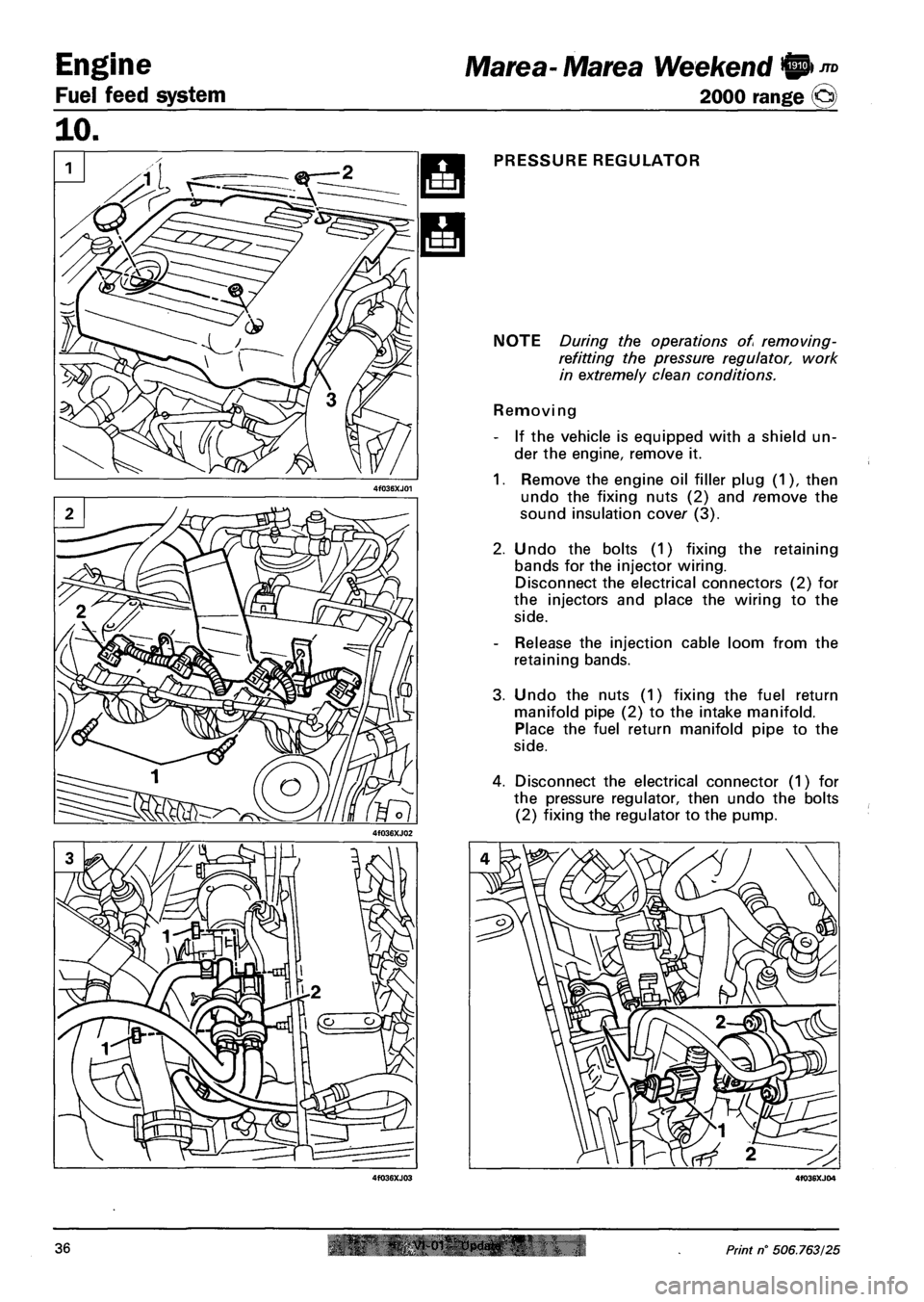
PRESSURE REGULATOR
NOTE During the operations of removing-
refitting the pressure regulator, work
in extremely clean conditions.
Removing
- If the vehicle is equipped with a shield un
der the engine, remove it.
1. Remove the engine oil filler plug (1), then
undo the fixing nuts (2) and remove the
sound insulation cover (3).
2. Undo the bolts (1) fixing the retaining
bands for the injector wiring.
Disconnect the electrical connectors (2) for
the injectors and place the wiring to the
side.
- Release the injection cable loom from the
retaining bands.
3. Undo the nuts (1) fixing the fuel return
manifold pipe (2) to the intake manifold.
Place the fuel return manifold pipe to the
side.
4. Disconnect the electrical connector (1) for
the pressure regulator, then undo the bolts
(2) fixing the regulator to the pump.
36 Print n° 506.763/25
Page 123 of 330
Marea-Marea Weekend H nD Engine
2000 range (Q) Fuel feed system
10.
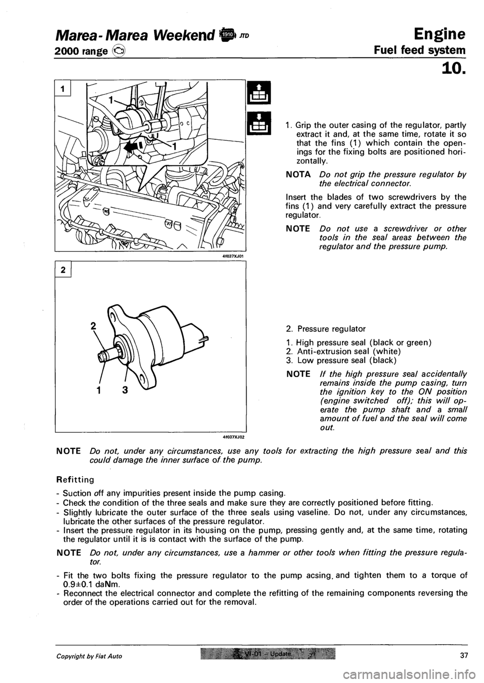
1. Grip the outer casing of the regulator, partly
extract it and, at the same time, rotate it so
that the fins (1) which contain the open
ings for the fixing bolts are positioned hori
zontally.
NOTA Do not grip the pressure regulator by
the electrical connector.
Insert the blades of two screwdrivers by the
fins (1) and very carefully extract the pressure
regulator.
NOTE Do not use a screwdriver or other
tools in the seal areas between the
regulator and the pressure pump.
2. Pressure regulator
1. High pressure seal (black or green)
2. Anti-extrusion seal (white)
3. Low pressure seal (black)
NOTE // the high pressure seal accidentally
remains inside the pump casing, turn
the ignition key to the ON position
(engine switched off); this will op
erate the pump shaft and a small
amount of fuel and the seal will come
out.
NOTE Do not, under any circumstances, use any tools for extracting the high pressure seal and this
could damage the inner surface of the pump.
Refitting
- Suction off any impurities present inside the pump casing.
- Check the condition of the three seals and make sure they are correctly positioned before fitting.
- Slightly lubricate the outer surface of the three seals using vaseline. Do not, under any circumstances,
lubricate the other surfaces of the pressure regulator.
- Insert the pressure regulator in its housing on the pump, pressing gently and, at the same time, rotating
the regulator until it is is contact with the surface of the pump.
NOTE Do not, under any circumstances, use a hammer or other tools when fitting the pressure regula
tor.
- Fit the two bolts fixing the pressure regulator to the pump acsing. and tighten them to a torque of
0.9±0.1 daNm.
- Reconnect the electrical connector and complete the refitting of the remaining components reversing the
order of the operations carried out for the removal.
Copyright by Fiat Auto |& yt-01 - Update 37
Page 260 of 330
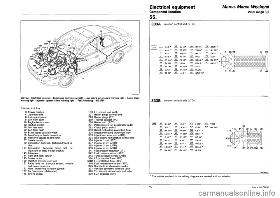
Electrical equipment
Component location
Marea-Marea Weekend
2000 range ©
55.
Starting - Electronic injection - Recharging and warning light - Low engine oil pressure warning
warning light - Injection system failure warning light - Fuel preheating (1910 JTD)
ight - Heater plugs
Component key
3 Power fusebox
4 Junction unit
6 Instrument panel
8 Left front earth
10 Engine battery earth
12 Ignition switch
18 Left rear earth
22 Left facia earth
40 Brake lights control switch
55 Front/engine lead connection
56 Fuel level gauge control unit
57 Inertia switch
70 Connection between dashborad/front ca
bles
127 Connection between front left ca
ble/cable on relay holder bracket
143 Alternator
144 Rpm and TDC sensor
145 Starter motor
150 Injection system relay feed
151 Relay feed for Lambda sensor, electric
fuel pump, injectors
152 Fuse protecting injection system
167 Air flow meter (debimeter)
168 Timing sensor
193 I.E. control unit earth
201 Heater plugs control unit
228 Heater plugs (TD)
289 Thermal contact (PCT)
290 Heater coil (PCT)
291 Potentiometer on accelerator pedal
292 Clutch pedal switch
303 Diesel preheating protection fuse
304 Diesel preheating protection relay
333 Injection control unit (JTD)
334 Dual engine temperature sender unit
336 Injector 1 cyl (JTD)
337 Injector 2. cyl (JTD)
338 Injector 3. cyl (JTD)
339 Injector 4. cyl (JTD)
341 Fuel pressure regulator (JTD)
342 Fuel pressure sensor (JTD)
343 Turbo pressure sensor (JTD)
344 I.E. protective fuse (JTD)
334B I.E. protective fuse (JTD)
345 Fuel temperature sensor (JTD)
375 Standardized diagnostic socket
377 Variable geometry solenoid valve
378 Throttle adjustment solenoid valve
379 EGR solenoid valve
333A Injection control unit (JTD)
JTD 1 N n.d. * 16 BV55* 48 BR 375 76 ZB 291 *
2 N n.d. * 17 CR 377 * 49 VB6A* 77 GN 291 *
3 N n.d. * 18 MG 127 51 BN 127 78 ZN 291 * A 4 Rn.d.* 19 AB 127 52 B 127 79 A 291 *
5 RN n.d. * 20 AG 127 58 CB n.d. * 80 MB 291 * ,
11 GV131 21 LN6A 59 LRn.d. * 81 AN 291 * ' >
13 SB 150 22 RV201B* 60 S 127
14 CL6A 24 SN 151 * 61 BL 292 * 1
15 BG55* 47 Ln.d. * 62 NZ 201B*
5 43 24
-o
T7
2 62 81
oooooooooooooooooc oooooooooooooooooc
oooooooooooooooooc oooooooooooooooooc
~7
63 44
333B Injection control unit (JTD)
JTD 82 SN55* 92 H342* 103 L168* 120 V337*
83 S55* 93 LR 343* 104 C 168* 121 MV 338 *
84 BN 334 * 94 HM 343 * 108 CB 341 *
85 LN 334 * 95 HN 343 * 109 HB 341 *
86 G 167* 97 CN 167* 111 MB 55*
88 NZ167* 99 R144* 114 VB 339 *
89 HR167* 100 B 144* 117 VN n.d. *
90 LG 342 * 101 N 144* 118 NVn.d. *
91 HV 342 * 102 BV168* 119 NL 336 *
114
AA 115 117
116.
89 97 82 90
oooooc OOOOOOG OOOOOOO 'OOOOOC
119113105106 98
* The cables involved in the wiring diagram are marked with an asterisk.
74 Print n° 506.763/23
Page 321 of 330
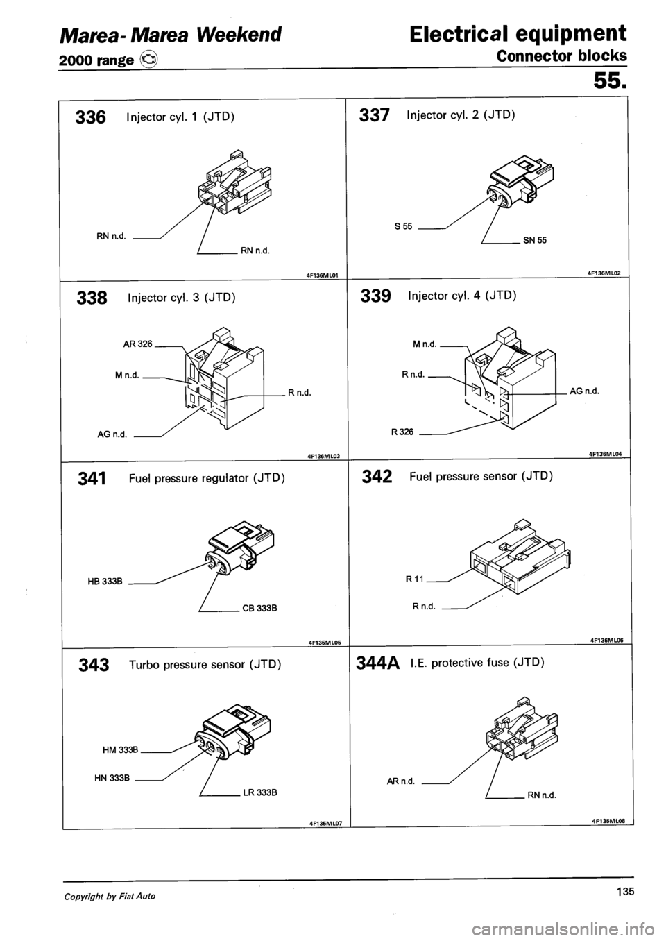
Marea- Marea Weekend
2000 range ©
Electrical equipment
Connector blocks
55.
336 Injector cyl. 1 (JTD)
RN n.d.
RN n.d.
338 Injector cyl. 3 (JTD)
AR326
Mn.d.
AG n.d.
. R n.d.
337 Injector cyl. 2 (JTD)
S55
SN55
339 Injector cyl. 4 (JTD)
Mn.d
Rn.d.
341 Fuel pressure regulator (JTD)
HB 333B
CB 333B
343 Turbo pressure sensor (JTD)
LR 333B
R326
AG n.d.
342 Fuel pressure sensor (JTD)
344A I.E. protective fuse (JTD)
AR n.d.
RN n.d.
Copyright by Fiat Auto 135