fuel type FIAT MAREA 2000 1.G User Guide
[x] Cancel search | Manufacturer: FIAT, Model Year: 2000, Model line: MAREA, Model: FIAT MAREA 2000 1.GPages: 330
Page 98 of 330
Engine
Fuel feed system
10.
4F012XJ03
Marea- Matea Weekend 9 ™
2000 range (Q)
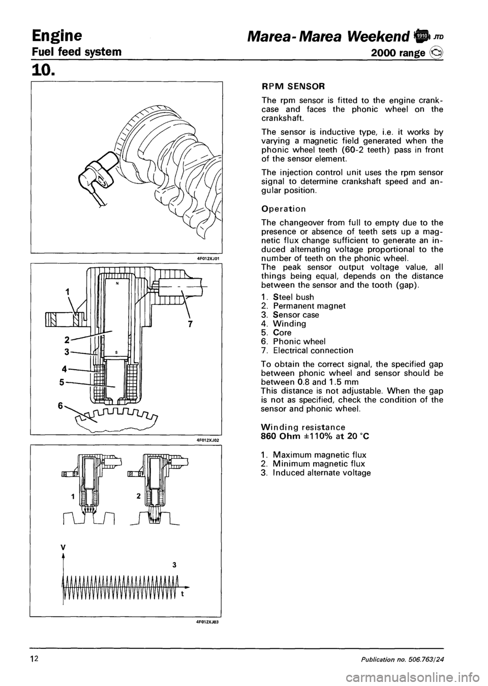
RPM SENSOR
The rpm sensor is fitted to the engine crank-
case and faces the phonic wheel on the
crankshaft.
The sensor is inductive type, i.e. it works by
varying a magnetic field generated when the
phonic wheel teeth (60-2 teeth) pass in front
of the sensor element.
The injection control unit uses the rpm sensor
signal to determine crankshaft speed and an
gular position.
Operation
The changeover from full to empty due to the
presence or absence of teeth sets up a mag
netic flux change sufficient to generate an in
duced alternating voltage proportional to the
number of teeth on the phonic wheel.
The peak sensor output voltage value, all
things being equal, depends on the distance
between the sensor and the tooth (gap).
1. Steel bush
2. Permanent magnet
3. Sensor case
4. Winding
5. Core
6. Phonic wheel
7. Electrical connection
To obtain the correct signal, the specified gap
between phonic wheel and sensor should be
between 0.8 and 1.5 mm
This distance is not adjustable. When the gap
is not as specified, check the condition of the
sensor and phonic wheel.
Winding resistance
860 Ohm ±110% at 20 °C
1. Maximum magnetic flux
2. Minimum magnetic flux
3. Induced alternate voltage
12 Publication no, 506.763/24
Page 99 of 330
Marea- Marea Weekend 9"°
2000 range ©
Engine
Fuel feed system
10.
TIMING SENSOR
The Hall effect sensor is fitted to the cylinder head and faces the camshaft pulley.
An opening on the pulley allows the timing sensor to detect the engine timing position and indicate it to
the injection control unit.
The injection control unit uses the timing sensor signal to detect TDC at the end of compression.
Operation
A semi-condulator layer, through which a current passes, immersed in a magnetic field (lines of force per
pendicular to the direction of the current), produces a difference in power, known as Hall voltage.
If the intensity of the current remains constant, the voltage produced only depends on the intensity of the
magnetic field. The intensity of the field can simply be altered periodically to produce a modulated electri
cal signal. Signal frequency is proportional to the speed with which the magnetic field changes.
To achieve this change, the sensor is crossed by a metal ring (inner part of the pulley) with an opening.
When it moves, the metal part of the ring covers the sensor to magnetic field and the output signal is
therefore low; Conversely, the sensor generates a high signal at the opening when the magnetic field is
present.
This signal, together with the rpm and TDC signals, allows the injection control unit to identify piston po
sition and determine injection point.
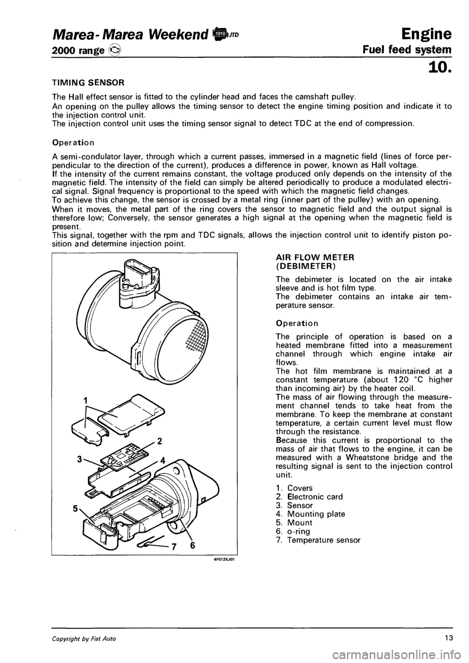
AIR FLOW METER
(DEBIMETER)
The debimeter is located on the air intake
sleeve and is hot film type.
The debimeter contains an intake air tem
perature sensor.
Operation
The principle of operation is based on a
heated membrane fitted into a measurement
channel through which engine intake air
flows.
The hot film membrane is maintained at a
constant temperature (about 120 °C higher
than incoming air) by the heater coil.
The mass of air flowing through the measure
ment channel tends to take heat from the
membrane. To keep the membrane at constant
temperature, a certain current level must flow
through the resistance.
Because this current is proportional to the
mass of air that flows to the engine, it can be
measured with a Wheatstone bridge and the
resulting signal is sent to the injection control
unit.
1. Covers
2. Electronic card
3. Sensor
4. Mounting plate
5. Mount
6. o-ring
7. Temperature sensor
Copyright by Fiat Auto 13
Page 100 of 330
Engine
Fuel feed system
10.
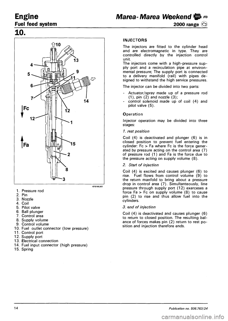
1. Pressure rod
2. Pin
3. Nozzle
4. Coil
5. Pilot valve
6. Ball plunger
7. Control area
8. Supply volume
9. Control volume
10. Fuel outlet connector (low pressure)
11. Control port
12. Supply port
13. Electrical connection
14. Fuel input connector (high pressure)
15. Spring
Marea- Marea Weekend 9 ™
2000 range (Q)
INJECTORS
The injectors are fitted to the cylinder head
and are electromagnetic in type. They are
controlled directly by the injection control
unit.
The injectors come with a high-pressure sup
ply port and a recirculation pipe at environ
mental pressure; The supply port is connected
to a delivery manifold (rail) with pipes de
signed to withstand the high service pressures.
The injector can be divided into two parts:
- Actuator/spray made up of a pressure rod
(1), pin (2) and nozzle (3);
- control solenoid made up of coil (4) and
pilot valve (5).
Operation
Injector operation may be divided into three
stages:
1. rest position
Coil (4) is deactivated and plunger (6) is in
closed position to prevent fuel entering the
cylinder: Fc > Fa where Fc is the force gener
ated by pressure acting on the control area (7)
of pressure rod (1) and Fa is the force due to
the pressure acting on supply volume (8).
2. Start of injection
Coil (4) is excited and causes plunger (6) to
rise. Fuel flows from control volume (9) to
the return manfold to bring about a pressure
drop in control area (7). Simultanteously, line
pressure through supply port (12) exerceses a
force Fa > Fc on supply volume (8) to cause
pin (2) to rise and thus allow fuel into the
cylinders.
3. end of injection
Coil (4) is deactivated and causes plunger (6)
to return to closed position. The resulting bal
ance of forces makes pin (2) return to rest po
sition and injection therefore ends.
14 Publication no. 506.763/24
Page 105 of 330
Marea- Marea Weekend 9 ™
2000 range (Q)
4F019XJ01
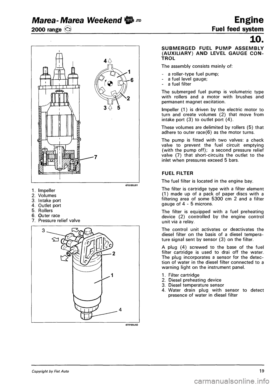
1. Impeller
2. Volumes
3. Intake port
4. Outlet port
5. Rollers
6. Outer race
7. Pressure relief valve
4F019XJ02
Engine
Fuel feed system
10.
SUBMERGED FUEL PUMP ASSEMBLY
(AUXILIARY) AND LEVEL GAUGE CON
TROL
The assembly consists mainly of:
- a roller-type fuel pump;
- a fuel level gauge;
- a fuel filter
The submerged fuel pump is volumetric type
with rollers and a motor with brushes and
permanent magnet excitation.
Impeller (1) is driven by the electric motor to
turn and create volumes (2) that move from
intake port (3) to outlet port (4).
These volumes are delimited by rollers (5) that
adhere to outer race(6) as the motor turns.
The pump is fitted with two valves: a check
valve to prevent the fuel circuit emptying
(with the pump off); a second pressure relief
valve (7) that short-circuits the outlet to the
inlet when pressures exceed 5 bars.
FUEL FILTER
The fuel filter is located in the engine bay.
The filter is cartridge type with a filter element
(1) made up of a pack of paper discs with a
filtering area of some 5300 cm 2 and a filter
gauge of 4 - 5 microns.
The filter is equipped with a fuel preheating
device (2) controlled by the engine control
unit via a relay.
The control unit activates or deactivates the
diesel filter on the basis of a diesel tempera
ture signal sent by sensor (3) on the filter.
A plug (4) screwed to the base of the fuel
filter cartridge is used to drai off the water.
The plug incorporates a sensor for the detec
tion of water in the diesel filter connected to a
warning light on the instrument panel.
1. Filter cartridge
2. Diesel preheating device
3. Diesel temperature sensor
4. Water drain plug with sensor to detect
presence of water in diesel filter
Copyright by Fiat Auto 19
Page 106 of 330
Engine
Fuel feed system
JTD Marea-Marea Weekend @
2000 range ©
10.
7^ £3
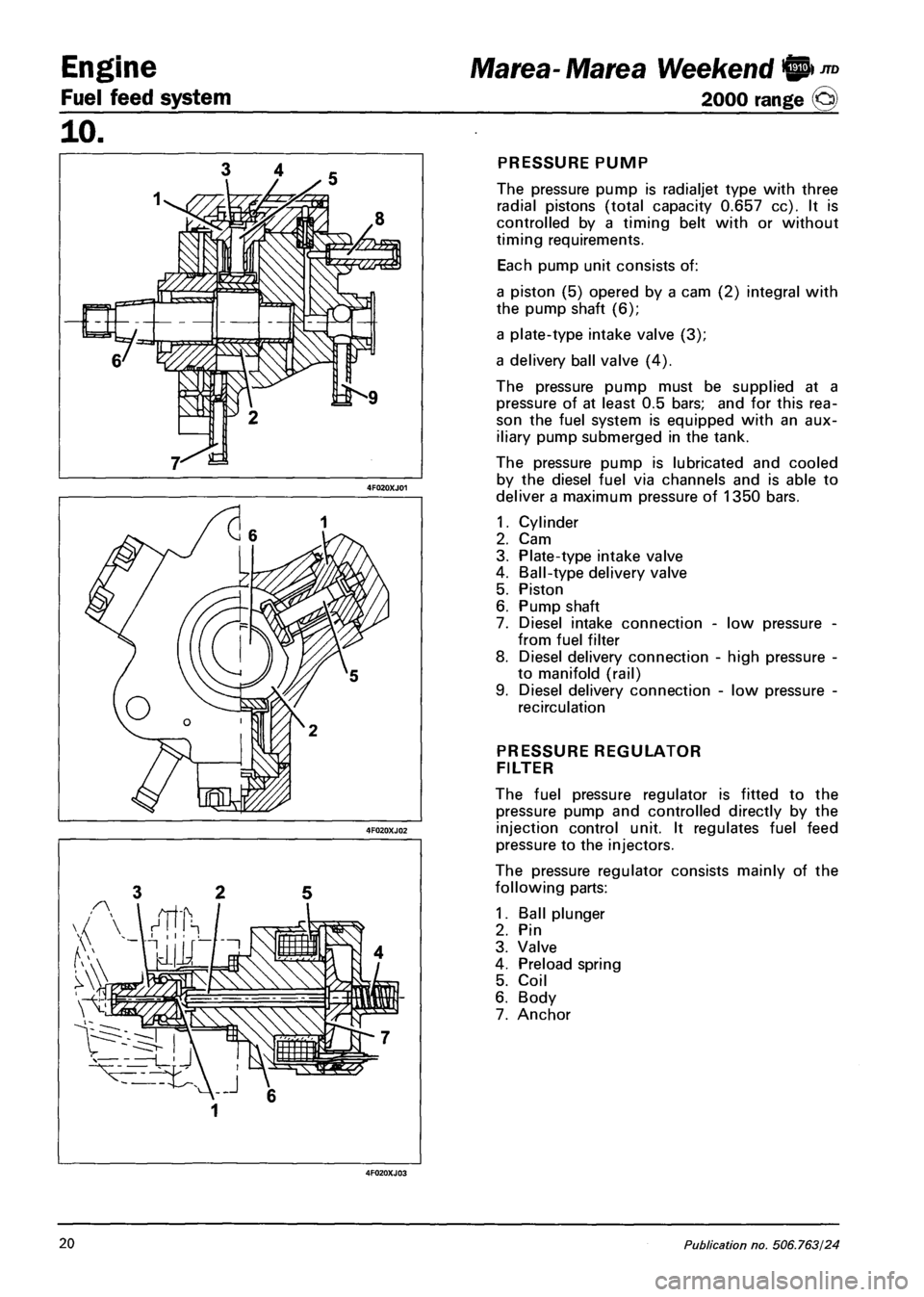
PRESSURE PUMP
The pressure pump is radialjet type with three
radial pistons (total capacity 0.657 cc). It is
controlled by a timing belt with or without
timing requirements.
Each pump unit consists of:
a piston (5) opered by a cam (2) integral with
the pump shaft (6);
a plate-type intake valve (3);
a delivery ball valve (4).
The pressure pump must be supplied at a
pressure of at least 0.5 bars; and for this rea
son the fuel system is equipped with an aux
iliary pump submerged in the tank.
The pressure pump is lubricated and cooled
by the diesel fuel via channels and is able to
deliver a maximum pressure of 1350 bars.
1.
2.
3.
4.
5.
6.
7.
8.
Cylinder
Cam
Plate-type intake valve
Ball-type delivery valve
Piston
Pump shaft
Diesel intake connection -
from fuel filter
Diesel delivery connection
to manifold (rail)
Diesel delivery connection
recirculation
low pressure
high pressure
low pressure
PRESSURE REGULATOR
FILTER
The fuel pressure regulator is fitted to the
pressure pump and controlled directly by the
injection control unit. It regulates fuel feed
pressure to the injectors.
The pressure regulator consists mainly of the
following parts:
1. Ball plunger
2. Pin
3. Valve
4. Preload spring
5. Coil
6. Body
7. Anchor
20 Publication no. 506.763/24
Page 109 of 330
Marea-Marea Weekend 9 Engine
2000 range ©) Fuel feed system
10.
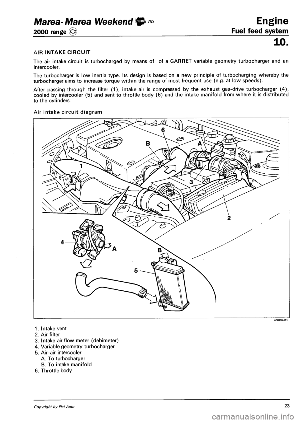
AIR INTAKE CIRCUIT
The air intake circuit is turbocharged by means of of a GARRET variable geometry turbocharger and an
intercooler.
The turbocharger is low inertia type. Its design is based on a new principle of turbocharging whereby the
turbocharger aims to increase torque within the range of most frequent use (e.g. at low speeds).
After passing through the filter (1), intake air is compressed by the exhaust gas-drive turbocharger (4),
cooled by intercooler (5) and sent to throttle body (6) and the intake manifold from where it is distributed
to the cylinders.
Air intake circuit diagram
4F023XJ01
1. Intake vent
2. Air filter
3. Intake airflow meter (debimeter)
4. Variable geometry turbocharger
5. Air-air intercooler
A. To turbocharger
B. To intake manifold
6. Throttle body
Copyright by Fiat Auto 23
Page 111 of 330
Marea- Marea Weekend 9
2000 range ©
Engine
Fuel feed system
10.
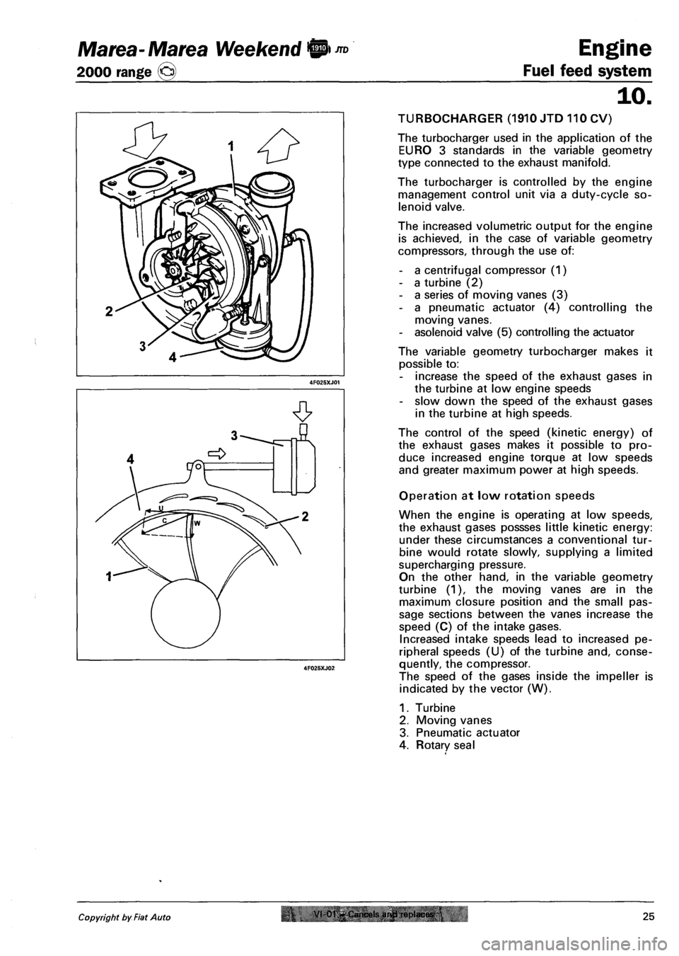
TURBOCHARGER (1910 JTD 110 CV)
The turbocharger used in the application of the
EURO 3 standards in the variable geometry
type connected to the exhaust manifold.
The turbocharger is controlled by the engine
management control unit via a duty-cycle so
lenoid valve.
The increased volumetric output for the engine
is achieved, in the case of variable geometry
compressors, through the use of:
- a centrifugal compressor (1)
- a turbine (2)
- a series of moving vanes (3)
- a pneumatic actuator (4) controlling the
moving vanes.
- asolenoid valve (5) controlling the actuator
The variable geometry turbocharger makes it
possible to:
- increase the speed of the exhaust gases in
the turbine at low engine speeds
- slow down the speed of the exhaust gases
in the turbine at high speeds.
The control of the speed (kinetic energy) of
the exhaust gases makes it possible to pro
duce increased engine torque at low speeds
and greater maximum power at high speeds.
Operation at low rotation speeds
When the engine is operating at low speeds,
the exhaust gases possses little kinetic energy:
under these circumstances a conventional tur
bine would rotate slowly, supplying a limited
supercharging pressure.
On the other hand, in the variable geometry
turbine (1), the moving vanes are in the
maximum closure position and the small pas
sage sections between the vanes increase the
speed (C) of the intake gases.
Increased intake speeds lead to increased pe
ripheral speeds (U) of the turbine and, conse
quently, the compressor.
The speed of the gases inside the impeller is
indicated by the vector (W).
1. Turbine
2. Moving vanes
3. Pneumatic actuator
4. Rotary seal
Copyright by Fiat Auto r VI-01-Cancels arwl replaces.25
Page 112 of 330
Engine
Fuel feed system
JTD Marea- Marea Weekend 9
2000 range @
10.
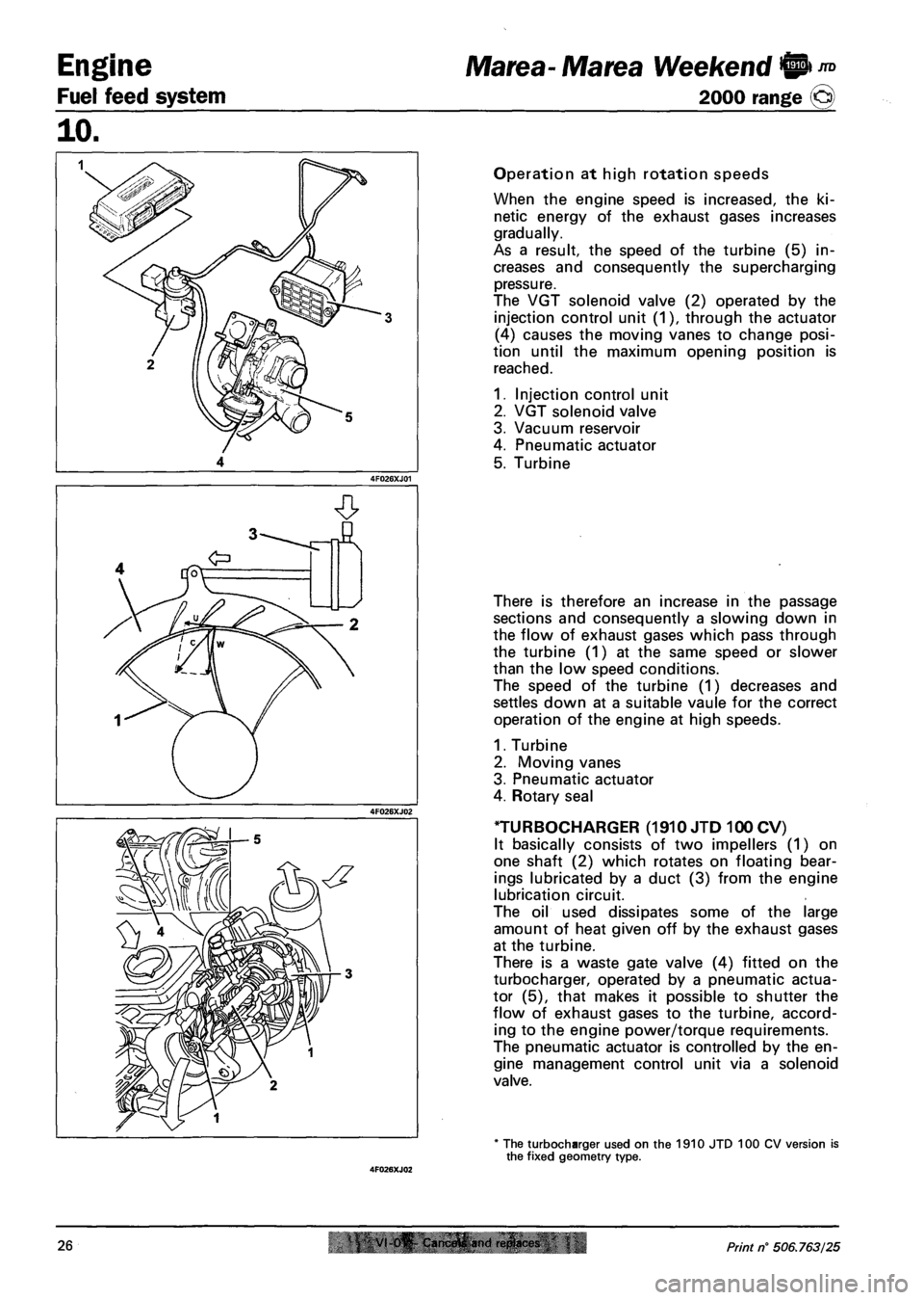
Operation at high rotation speeds
When the engine speed is increased, the ki
netic energy of the exhaust gases increases
gradually.
As a result, the speed of the turbine (5) in
creases and consequently the supercharging
pressure.
The VGT solenoid valve (2) operated by the
injection control unit (1), through the actuator
(4) causes the moving vanes to change posi
tion until the maximum opening position is
reached.
1. Injection control unit
2. VGT solenoid valve
3. Vacuum reservoir
4. Pneumatic actuator
5. Turbine
There is therefore an increase in the passage
sections and consequently a slowing down in
the flow of exhaust gases which pass through
the turbine (1) at the same speed or slower
than the low speed conditions.
The speed of the turbine (1) decreases and
settles down at a suitable vaule for the correct
operation of the engine at high speeds.
1. Turbine
2. Moving vanes
3. Pneumatic actuator
4. Rotary seal
TURBOCHARGER (1910 JTD 100 CV)
It basically consists of two impellers (1) on
one shaft (2) which rotates on floating bear
ings lubricated by a duct (3) from the engine
lubrication circuit.
The oil used dissipates some of the large
amount of heat given off by the exhaust gases
at the turbine.
There is a waste gate valve (4) fitted on the
turbocharger, operated by a pneumatic actua
tor (5), that makes it possible to shutter the
flow of exhaust gases to the turbine, accord
ing to the engine power/torque requirements.
The pneumatic actuator is controlled by the en
gine management control unit via a solenoid
valve.
* The turbocharger used on the 1910 JTD 100 CV version is the fixed geometry type.
26 VI 0^ Cam.frtfi and ri!plact<& Print n° 506.763/25
Page 139 of 330
Marea-Marea Weekend Electrical equipment
2000 range (§) Location of components on the car
55.
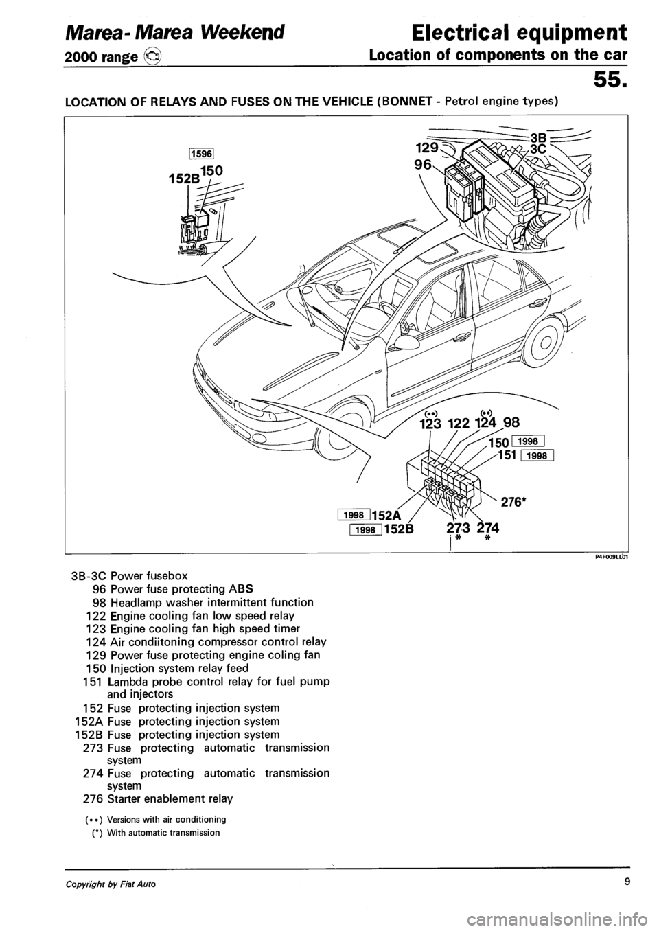
LOCATION OF RELAYS AND FUSES ON THE VEHICLE (BONNET - Petrol engine types)
Fi998l152B 273 274 i * *
3B-3C Power fusebox
96 Power fuse protecting ABS
98 Headlamp washer intermittent function
122 Engine cooling fan low speed relay
123 Engine cooling fan high speed timer
124 Air condiitoning compressor control relay
129 Power fuse protecting engine coling fan
150 Injection system relay feed
151 Lambda probe control relay for fuel pump
and injectors
152 Fuse protecting injection system
152A Fuse protecting injection system
152B Fuse protecting injection system
273 Fuse protecting automatic transmission
system
274 Fuse protecting automatic transmission
system
276 Starter enablement relay
(••) Versions with air conditioning
(*) With automatic transmission
Copyright by Fiat Auto 9
Page 186 of 330
Marea-Marea Weekend Electrical equipment
2000 range (§) Wiring diagrams
55.
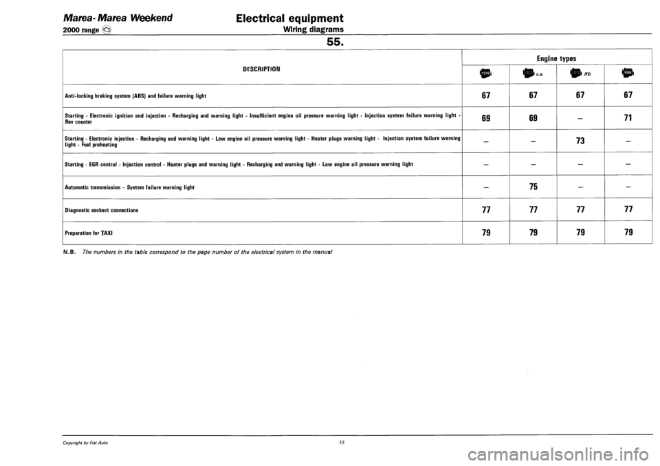
DESCRIPTION
Engine types
DESCRIPTION 10i 0) c.a. 01/70
ANTI-LOCKING BRAKING SYSTEM (ABS) AND FAILURE WARNING LIGHT 67 67 67 67
STARTING - ELECTRONIC IGNITION AND INJECTION - RECHARGING AND WARNING LIGHT - INSUFFICIENT ENGINE OIL PRESSURE WARNING LIGHT - INJECTION SYSTEM FAILURE WARNING LIGHT -
REV COUNTER 69 69 — 71
STARTING - ELECTRONIC INJECTION - RECHARGING AND WARNING LIGHT - LOW ENGINE OIL PRESSURE WARNING LIGHT - HEATER PLUGS WARNING LIGHT - INJECTION SYSTEM FAILURE WARNING
LIGHT - FUEL PREHEATING — — 73 —
STARTING - EGR CONTROL - INJECTION CONTROL - HEATER PLUGS AND WARNING LIGHT - RECHARGING AND WARNING LIGHT - LOW ENGINE OIL PRESSURE WARNING LIGHT — — — —
AUTOMATIC TRANSMISSION - SYSTEM FAILURE WARNING LIGHT — 75 — —
DIAGNOSTIC SOCKECT CONNECTIONS 77 77 77 77
PREPARATION FOR TAXI 79 79 79 79
FM.B. The numbers in the table correspond to the page number of the electrical system in the manual
Copyright by Fiat Auto III