fuse box diagram FIAT MAREA 2000 1.G Owner's Guide
[x] Cancel search | Manufacturer: FIAT, Model Year: 2000, Model line: MAREA, Model: FIAT MAREA 2000 1.GPages: 330
Page 256 of 330
Electrical equipment
Component location
Marea-Marea Weekend
2000 range ©
55.
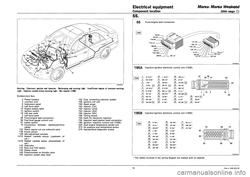
Starting - Electronic ignition and injection - Recharging and warning light
light - Injection system failure warning light - Rev counter (1596)
Insufficient engine oil pressure warning
Component key
3 Power fusebox
4 Junction unit:
6 Instrument panel
8 Left front earth
10 Engine battery earth
12 Ignition switch
18 Left rear earth
2 Left facia earth
55 Front/engine lead connection
56 Fuel level gauge control unit
57 Inertia switch
70 Connection between dashborad/front
cables
132 Petrol vapour cut out solenoid valve
136 Knock sensor
138 Idle adjustment actuator
141A Heated Lambda sensor (upstream of
cat.)
141 B Heated Lambda sensor (downstream of
cat.)
143 Alternator
144 Rpm and TDC sensor
145 Starter motor
146 Potentiometer on throttle valve
150 Injection system relay feed
152 Fuse protecting injection system
155 Ignition coil unit
156 Spark plugs
162 Injector (1st)
163 Injector (2nd)
164 Injector (3rd)
165 Injector (4th)
168 Timing sensor
193 Earth for electronic injection
194 Injection lead/injector braid connection
195 Ignition/ injection control unit (1596)
334 Dual engine temperature sender unit
373 Air pressure and temperature sensor
375 Standardized diagnostic socket
55 Front/engine lead connection
1596
CN6A.
HG6A.
* HN 6A
1 CN n.d.
MB6A.
NZ8_
* ZB n.d
*RG195A_
HM6A
CN n.d. HN 143 *
HG 142
1 95A Injection/ignition electronic control unit (1596)
1596 1 N 141A* 20 L 141A* 29 RN n.d. *
2 NZ141B* 21 BN 127 35 B 127
4 L6A* 23 GN 6A* 36 LR252 [c*
5 V252 0 23 GN70 0 40 AG 127
9 LN 141A* 24 B141B* 41 MG 127
12 R 141B* 25 BR n.d. 0 44 Vn.d.*
13 GV131 25 BR 375 * 46 BG 268 [a
14 AB 127 26 LN6A* 47 C n.d. *
15 SB 150* 27 N 193* 48 S 127
16 GN 252 [cal 28 N 193* 49 NZ252
27 282,9 41 52
O I I I I I I -r-r-r'n , , r'l -r-
rrrri '/ 1 1 1 1 1 1 1 1 1 1 1 \1 L/-HJ 'A i I I i i ,I
40
1 95B Injection/ignition electronic control unit (1596)
1596 53 R144* 65 VB 138* JL. NZn.d. *
54 N n.d. * 66 LR 155 * _ZL HM194*
55 ZB 278 * 67 B 144* _7JL HV194*
56 L136* 68 V278*
57 C138* 69 B 168*
58 HN 138* 70 Z136*
59 GN 155 * 71 HG 194 *
60 S 146* 72 HL194*
62 SN 339 * 75 RN 278 *
64 GR138* 76 BR 146 *
74
67-Jf Mill i i r r-l I I I
60-
IE
L -j |l
53 59
The cables involved in the wiring diagram are marked with an asterisk.
70 Print n° 506.763/23
Page 258 of 330
Electrical equipment
Component location
Marea-Marea Weekend
2000 range ®
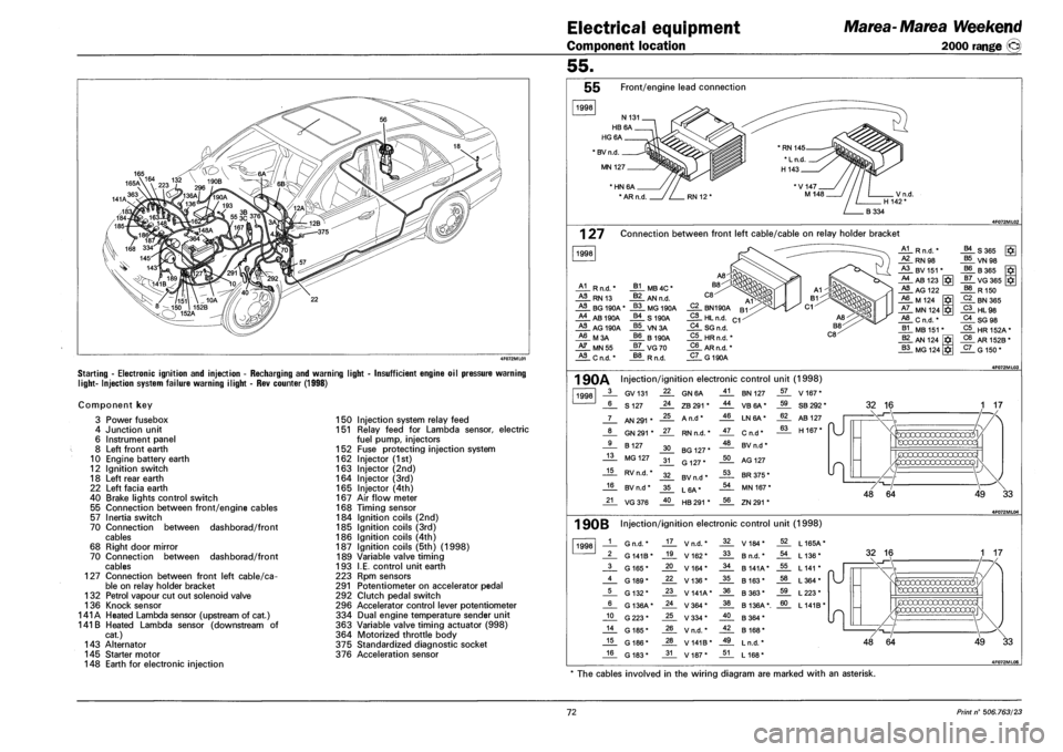
Starting - Electronic ignition and injection - Recharging and warning light
light- Injection system failure warning ilight - Rev counter (1998)
Insufficient engine oil pressure warning
Component key
3 Power fusebox
4 Junction unit
6 Instrument panel
8 Left front earth
10 Engine battery earth
12 Ignition switch
18 Left rear earth
22 Left facia earth
40 Brake lights control switch
55 Connection between front/engine cables
57 Inertia switch
70 Connection between dashborad/front
cables
68 Right door mirror
70 Connection between dashborad/front
cables
127 Connection between front left cable/ca
ble on relay holder bracket
132 Petrol vapour cut out solenoid valve
136 Knock sensor
141A Heated Lambda sensor (upstream of cat.)
141 B Heated Lambda sensor (downstream of
cat.)
143 Alternator
145 Starter motor
148 Earth for electronic injection
150 Injection system relay feed
151 Relay feed for Lambda sensor, electric
fuel pump, injectors
152 Fuse protecting injection system
162 Injector (1st)
163 Injector (2nd)
164 Injector (3rd)
165 Injector (4th)
167 Air flow meter
168 Timing sensor
184 Ignition coils (2nd)
185 Ignition coils (3rd)
186 Ignition coils (4th)
187 Ignition coils (5th) (1998)
189 Variable valve timing
193 I.E. control unit earth
223 Rpm sensors
291 Potentiometer on accelerator pedal
292 Clutch pedal switch
296 Accelerator control lever potentiometer
334 Dual engine temperature sender unit
363 Variable valve timing actuator (998)
364 Motorized throttle body
375 Standardized diagnostic socket
376 Acceleration sensor
55.
55 Front/engine lead connection
1998
* BV n.d
MN 127
' HN 6A
* AR n.d
1 27 Connection between front left cable/cable on relay holder bracket
1998
A1 R n.d.'
HL RN 13
HL BG 190A
A4 AB 190A
HL AG 190A
A6 M3A
HL MN55
HL C n.d. *
J*L MB 4C *
J*L AN n.d.
_§§_ MG 190A
_§£. S 190A
VN3A
66 B190A
_§7_ VG70
R n.d.
C2 BN190A
_2L HL n.d.
C4_ SG n.d.
C5 HRn.fi.'
C6 AR n.d. *
_5L G 190A
A1 R n.d. * B4 S365
HL RN98 B5 VN 98 A3 BV 151 * B6 B365 A4 AB 123 J7_ VG365 J*I
HL AG 122 B8 R 150 A6 M 124 C2 BN365 A7 MN 124 C3 HL98 A8 Cn.d.* C4 SG 98 B1 MB 151 * C5 HR152A* B2 AN 124 C6 AR 152B *
B3 MG 124 C7 G 150*
1 90A Injection/ignition electronic control unit (1998)
1998 3 GV131 22 GN6A 41 BN 127 57 V 167*
6 S 127 24 ZB 291 * 44 VB6A* 59 SB 292 *
7 AN 291 * 25 A n.d* 46 LN6A* 62 AB 127
"U 8 GN 291 * 27 RN n.d. * 47 Cn.d* 63 H 167* "U
9 B 127 30 BG 127 * 48 BV n.d *
13 MG 127 31 G 127* 50 AG 127
15 RV n.d. * 32 BV n.d * 53 BR 375 *
16 BV n.d * 35 L6A* 54 MN 167 *
21 VG376 40 HB 291 * 56 ZN 291 *
32 16
49 33
1 90B Injection/ignition electronic control unit (1998)
1998 1 G n.d. * 17 V n.d. * 32 V184* 52 L165A*
2 G 141B* 19 V162* 33 B n.d. * 54 L 136*
3 G 165* 20 V164* 34 B 141A* 55 L 141 *
4 G 189* 22 V136* 35 B 163* 58 L364*
5 G 132* 23 V141A* 36 B363* 59 L223*
6 G 136A* 24 V364* 38 B 136A*. 60 L141B*
10 G223* 25 V334* 40 B364*
14 G 185* 26 V n.d. * 42 B 168*
15 G 186* 28 V 141B* 49 L n.d. *
16 G 183* 31 V187* 51 L 168*
49 33
* The cables involved in the wiring diagram are marked with an asterisk.
72 Print n° 506.763/23
Page 260 of 330
Electrical equipment
Component location
Marea-Marea Weekend
2000 range ©
55.
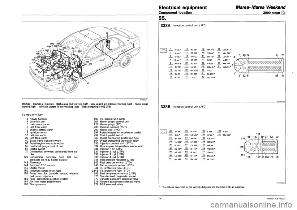
Starting - Electronic injection - Recharging and warning light - Low engine oil pressure warning
warning light - Injection system failure warning light - Fuel preheating (1910 JTD)
ight - Heater plugs
Component key
3 Power fusebox
4 Junction unit
6 Instrument panel
8 Left front earth
10 Engine battery earth
12 Ignition switch
18 Left rear earth
22 Left facia earth
40 Brake lights control switch
55 Front/engine lead connection
56 Fuel level gauge control unit
57 Inertia switch
70 Connection between dashborad/front ca
bles
127 Connection between front left ca
ble/cable on relay holder bracket
143 Alternator
144 Rpm and TDC sensor
145 Starter motor
150 Injection system relay feed
151 Relay feed for Lambda sensor, electric
fuel pump, injectors
152 Fuse protecting injection system
167 Air flow meter (debimeter)
168 Timing sensor
193 I.E. control unit earth
201 Heater plugs control unit
228 Heater plugs (TD)
289 Thermal contact (PCT)
290 Heater coil (PCT)
291 Potentiometer on accelerator pedal
292 Clutch pedal switch
303 Diesel preheating protection fuse
304 Diesel preheating protection relay
333 Injection control unit (JTD)
334 Dual engine temperature sender unit
336 Injector 1 cyl (JTD)
337 Injector 2. cyl (JTD)
338 Injector 3. cyl (JTD)
339 Injector 4. cyl (JTD)
341 Fuel pressure regulator (JTD)
342 Fuel pressure sensor (JTD)
343 Turbo pressure sensor (JTD)
344 I.E. protective fuse (JTD)
334B I.E. protective fuse (JTD)
345 Fuel temperature sensor (JTD)
375 Standardized diagnostic socket
377 Variable geometry solenoid valve
378 Throttle adjustment solenoid valve
379 EGR solenoid valve
333A Injection control unit (JTD)
JTD 1 N n.d. * 16 BV55* 48 BR 375 76 ZB 291 *
2 N n.d. * 17 CR 377 * 49 VB6A* 77 GN 291 *
3 N n.d. * 18 MG 127 51 BN 127 78 ZN 291 * A 4 Rn.d.* 19 AB 127 52 B 127 79 A 291 *
5 RN n.d. * 20 AG 127 58 CB n.d. * 80 MB 291 * ,
11 GV131 21 LN6A 59 LRn.d. * 81 AN 291 * ' >
13 SB 150 22 RV201B* 60 S 127
14 CL6A 24 SN 151 * 61 BL 292 * 1
15 BG55* 47 Ln.d. * 62 NZ 201B*
5 43 24
-o
T7
2 62 81
oooooooooooooooooc oooooooooooooooooc
oooooooooooooooooc oooooooooooooooooc
~7
63 44
333B Injection control unit (JTD)
JTD 82 SN55* 92 H342* 103 L168* 120 V337*
83 S55* 93 LR 343* 104 C 168* 121 MV 338 *
84 BN 334 * 94 HM 343 * 108 CB 341 *
85 LN 334 * 95 HN 343 * 109 HB 341 *
86 G 167* 97 CN 167* 111 MB 55*
88 NZ167* 99 R144* 114 VB 339 *
89 HR167* 100 B 144* 117 VN n.d. *
90 LG 342 * 101 N 144* 118 NVn.d. *
91 HV 342 * 102 BV168* 119 NL 336 *
114
AA 115 117
116.
89 97 82 90
oooooc OOOOOOG OOOOOOO 'OOOOOC
119113105106 98
* The cables involved in the wiring diagram are marked with an asterisk.
74 Print n° 506.763/23
Page 262 of 330
Electrical equipment
Component location
Marea-Marea Weekend
2000 range ©
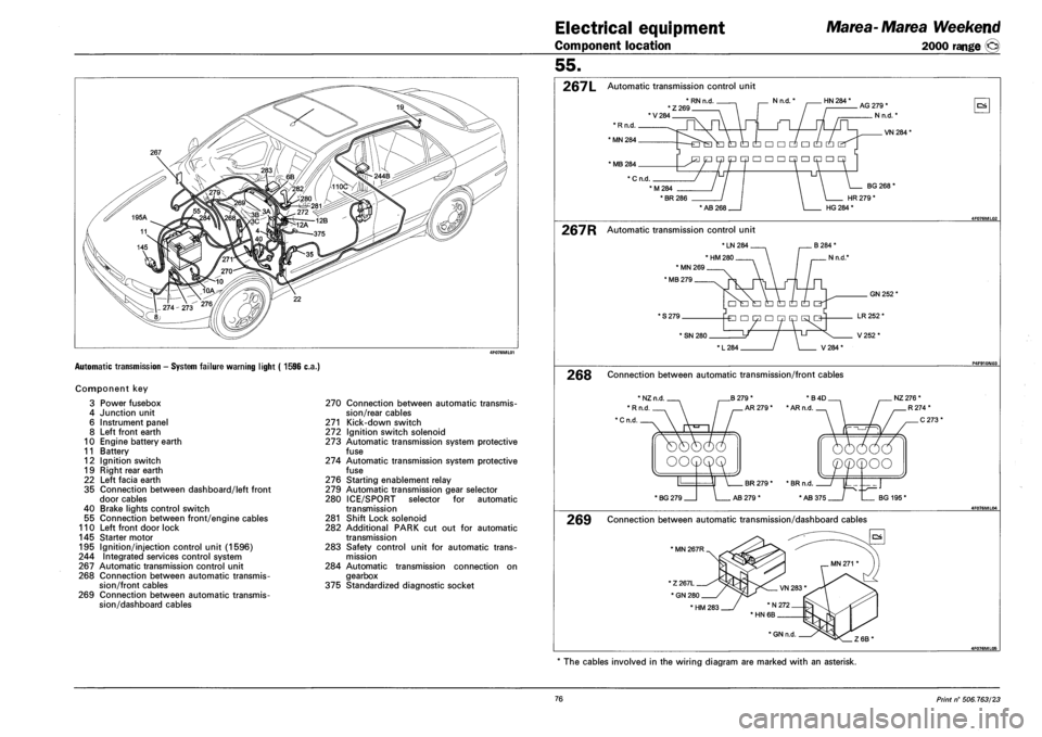
Automatic transmission - System failure warning light ( 1596 c.a.)
Component key
3 Power fusebox
4 Junction unit
6 Instrument panel
8 Left front earth
10 Engine battery earth
11 Battery
12 Ignition switch
19 Right rear earth
22 Left facia earth
35 Connection between dashboard/left front
door cables
40 Brake lights control switch
55 Connection between front/engine cables
110 Left front door lock
145 Starter motor
195 Ignition/injection control unit (1596)
244 Integrated services control system
267 Automatic transmission control unit
268 Connection between automatic transmis
sion/front cables
269 Connection between automatic transmis
sion/dashboard cables
270 Connection between automatic transmis
sion/rear cables
271 Kick-down switch
272 Ignition switch solenoid
273 Automatic transmission system protective
fuse
274 Automatic transmission system protective
fuse
276 Starting enablement relay
279 Automatic transmission gear selector
280 ICE/SPORT selector for automatic
transmission
281 Shift Lock solenoid
282 Additional PARK cut out for automatic
transmission
283 Safety control unit for automatic trans
mission
284 Automatic transmission connection on
gearbox
375 Standardized diagnostic socket
55.
267L Automatic transmission control unit
*RNn.d , . Nn.d.' HN 284 * *Z269 'V284
AG 279 *
N n.d.'
OS
VN 284*
* MB 284
* C n.d.
M284
• BR 286
BG 268'
HR 279 *
* AB 268 HG 284 *
267R Automatic transmission control unit
* LN 284
' HM 280
* MN 269
' MB 279
* S 279.
GN 252'
* SN 280.
L284 / \ V284*
LR 252 *
V252*
268 Connection between automatic transmission/front cables
B 279 *
AR 279 *
*B4D NZ 276 *
• AR n.d
' BG 279 AB 279 * BG 195'
269 Connection between automatic transmission/dashboard cables
' MN 267R
The cables involved in the wiring diagram are marked with an asterisk.
76 Print n° 506.763/23
Page 264 of 330
Electrical equipment
Component location
Marea-Matea Weekend
2000 range ©
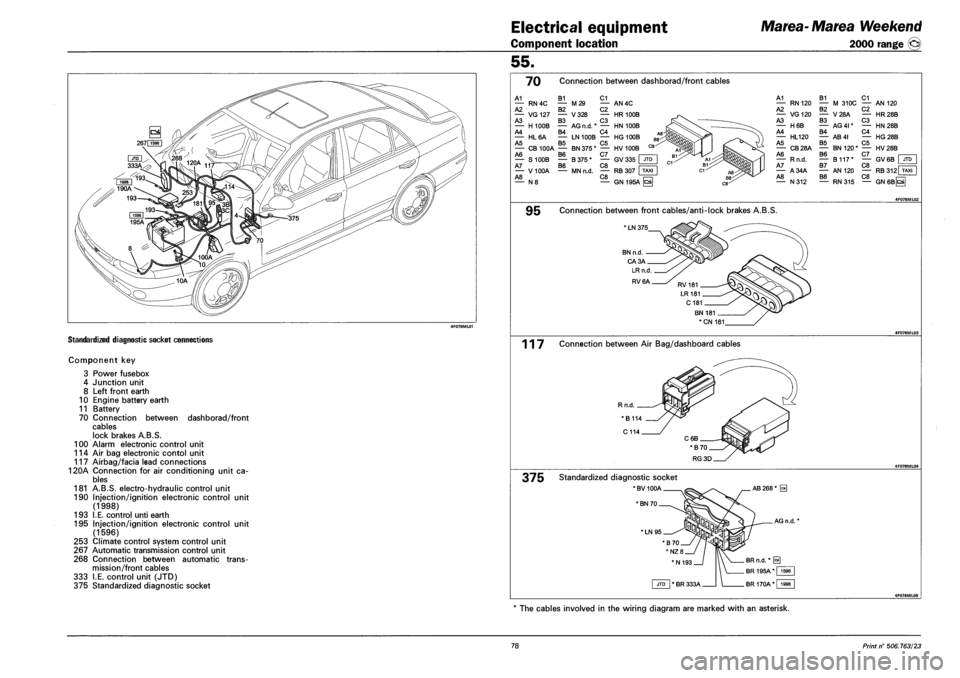
STANDARDIZED DIAGNOSTIC SOCKET CONNECTIONS
COMPONENT KEY
3
4
8
10
11
70
100
114
117
120A
181
190
193
195
253
267
268
333
375
Power fusebox
Junction unit
Left front earth
Engine battery earth
Battery
Connection between dashborad/front
cables
lock brakes A.B.S.
Alarm electronic control unit
Air bag electronic contol unit
Airbag/facia lead connections
Connection for air conditioning unit ca
bles
A.B.S. electro-hydraulic control unit
Injection/ignition electronic control
(1998)
I.E. control unti earth
Injection/ignition electronic control
(1596)
Climate control system control unit
Automatic transmission control unit
Connection between automatic trans
mission/front cables
I.E. control unit (JTD)
Standardized diagnostic socket
unit
unit
55.
70 Connection between dashborad/front cables
A1
A2 RN4C B1 C1 — M29 — AN4C B2 C2 — HR100B C3 AG n.d.* — HN 100B B4 C4 — LN100B — HG100B B5 C5 — CB100A — BN375* — HV 100B A6 B6 C7 — S100B — B375* — GV335 A7 B8 C8 — V100A — MNn.d. — RB 307 A8 C8 — N 8 — GN 195A
— VG 127 — V 328 A3 B3 — H100B — A4 — HL6A A5
A1 — RN120 A2 — VG120 A3 — H6B A4 — HL120 A5 — CB28A A6 — Rn.d. A7 — A34A A8 — N312
B1 C1 — M 310C — AN 120 B2 — V28A B3 — AG4I* B4 — AB4I B5 — BN120" B6 — B117* B7 — AN 120 B8 — RN315
C2 — HR28B C3 — HN28B C4 — HG28B C5 — HV28B C7 I — GV6B | JTD C8 — RB 312 TAXI C8 —I — GN6BQ
9B Connection between front cables/anti-lock brakes A.B.S.
* LN 375
BN n.d
CA3A
*CN 181
117 Connection between Air Bag/dashboard cables
Rn.d.
375 Standardized diagnostic socket
*BV100A
* BN 70
'LN95
The cables involved in the wiring diagram are marked with an asterisk.
78 Print n° 506.763/23
Page 266 of 330
Electrical equipment
Component location
Marea-Marea Weekend
2000 range ©
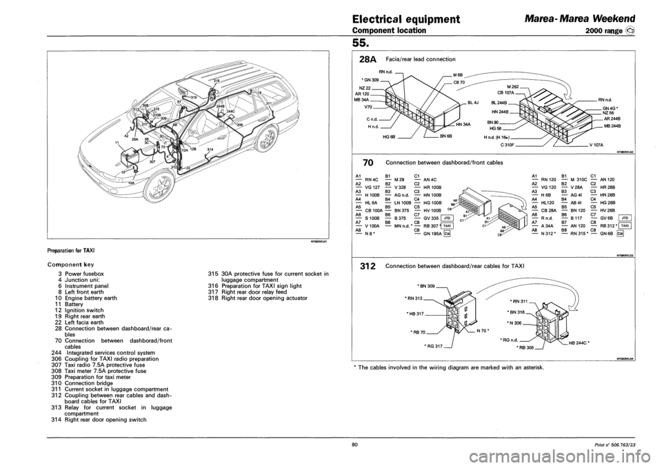
Preparation for TAXI
Component key
3 Power fusebox
4 Junction uni:
6 Instrument panel
8 Left front earth
10 Engine battery earth
11 Battery
12 Ignition switch
19 Right rear earth
22 Left facia earth
28 Connection between dashboard/rear ca
bles
70 Connection between dashborad/front
cables
244 Integrated services control system
306 Coupling for TAXI radio preparation
307 Taxi radio 7.5A protective fuse
308 Taxi meter 7.5A protective fuse
309 Preparation for taxi meter
310 Connection bridge
311 Current socket in luggage compartment
312 Coupling between rear cables and dash
board cables for TAXI
313 Relay for current socket in luggage
compartment
314 Right rear door opening switch
315 30A protective fuse for current socket in
luggage compartment
316 Preparation for TAXI sign light
317 Right rear door relay feed
318 Right rear door opening actuator
55.
28A Facia/rear lead connection
RN n.d.
' GN 309 .
NZ 22.
AR 120 _
MB34A.
V70.
M262
CB 107A
BL 244B.
HN 244B.
. HN 34A BN 90 _
HG56.
HG 6B BN 6B H n.d.(H 16.) _
C310F
RN n.d.
_ GN 4G * _NZ 56
AR244B
. MB 244B
V107A
70 Connection between dashborad/front cables
A1 B1 C1 — RN4C — M29 — AN4C A2 B2 C2 — VG127 — V328 — HR 100B A3 B3 C3 — H100B — AG n.d. — HN 100B A4 B4 C4 — HL6A — LN100B — HG 100B A5 B5 C5 — CB100A — BN375 — HV100B A6 B6 C7 — S100B — B375 — GV335 JTD A7 B8 C8 — V100A — MNn.d. *— RB 307 H TAXI A8 C8 n=n — N8* — GN195A ^
A1 B1 C1 — RN 120 — M 310C — AN 120 A2 B2 C2 — VG120 — V28A — HR28B A3 B3 C3 — H6B — AG4I — HN28B A4 B4 C4 — HL120 — AB4I — HG28B A5 B5 C5 — CB28A — BN120 — HV28B A6 B6 C7 — Rn.d. — B117 — GV6B A7 B7 C8 — A34A — AN 120 — RB312* T A8 B8 C8 — N312* — RN315* — GN 6B hs
JTD
31 2 Connection between dashboard/rear cables for TAXI
'HB317.
* RB 70.
' RG 317 HB 244C *
4F080ML04
The cables involved in the wiring diagram are marked with an asterisk.
80 Print n° 506.763/23