warning light FIAT MAREA 2000 1.G Owner's Guide
[x] Cancel search | Manufacturer: FIAT, Model Year: 2000, Model line: MAREA, Model: FIAT MAREA 2000 1.GPages: 330
Page 228 of 330
Electrical equipment
Component location
Marea-Marea Weekend
2000 range @)
55.
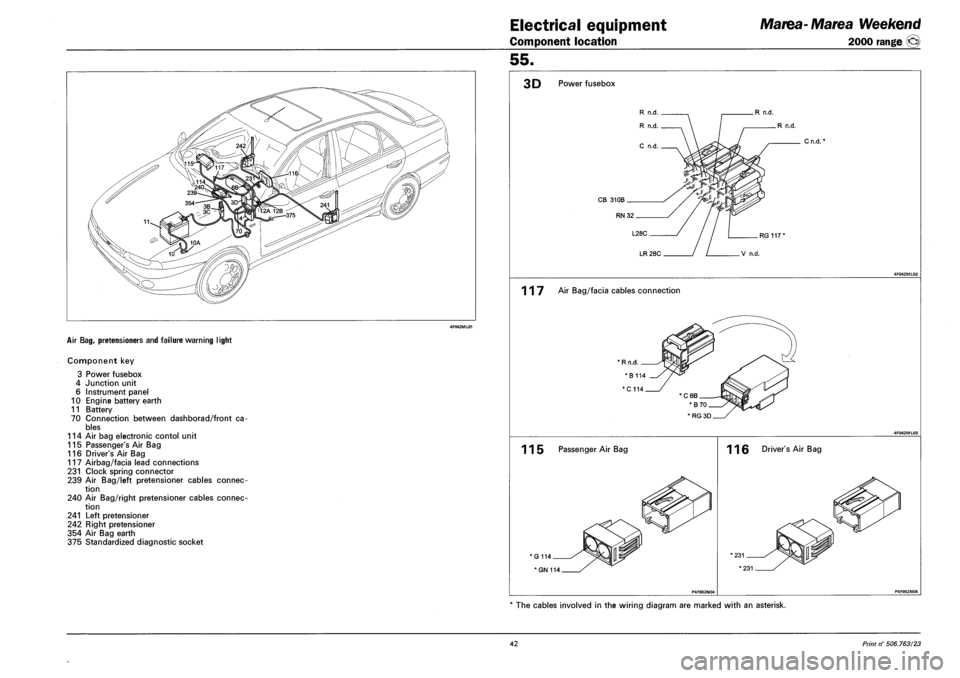
AIR BAG, PRETENSIONERS AND FAILURE WARNING LIGHT
Component key
3 Power fusebox
4 Junction unit
6 Instrument panel
10 Engine battery earth
11 Battery
70 Connection between dashborad/front ca
bles
114 Air bag electronic contol unit
115 Passenger's Air Bag
116 Driver's Air Bag
117 Airbag/facia lead connections
231 Clock spring connector
239 Air Bag/left pretensioner cables connec
tion
240 Air Bag/right pretensioner cables connec
tion
241 Left pretensioner
242 Right pretensioner
354 Air Bag earth
375 Standardized diagnostic socket
3D Power fusebox
R n.d.
R n.d.
CB 310B
RN32
Cn.d.
LR 28C
117 Air Bag/facia cables connection
115 Passenger Air Bag
G114
* GN 114
116 Driver's Air Bag
The cables involved in the wiring diagram are marked with an asterisk.
42 Print n° 506.763/23
Page 229 of 330
![FIAT MAREA 2000 1.G Owners Guide Marea-Marea Weekend
2000 range ©
Electrical equipment
Wiring diagrams
55.
AIR BAG WITH SIDE BAG AND PRETENSIONERS AND FAILURE WARNING LIGHT
11
XXXX
ESS§ 1 1 10
HI
C —i
375 JL
~i]r 3D
FIAT MAREA 2000 1.G Owners Guide Marea-Marea Weekend
2000 range ©
Electrical equipment
Wiring diagrams
55.
AIR BAG WITH SIDE BAG AND PRETENSIONERS AND FAILURE WARNING LIGHT
11
XXXX
ESS§ 1 1 10
HI
C —i
375 JL
~i]r 3D](/img/10/4653/w960_4653-228.png)
Marea-Marea Weekend
2000 range ©
Electrical equipment
Wiring diagrams
55.
AIR BAG WITH SIDE BAG AND PRETENSIONERS AND FAILURE WARNING LIGHT
11
XXXX
ESS§ 1 1 10
HI
C —i
375 JL
~i]r 3D
RG
$n 70
B C
12
rhrp I Y Y fl I 15/54 J. I Int/Q J DOS
[a
15/54 ' , I lnt/a J pos 30 50 Irrt stazr
71.
116
117
RG
2311
LN
241
356
358
VN--VN v£v
239
VN
-ZB--RN-
-HR
352
HB-g-HB' HL-
n i
T 2 13
CB R _l L
LTJ
lKwtt
114
2 4 6 8 10 IS 14 16 18 20 22 24 26 28 30 32 34 36 38 40 42 44 46 48 50 1 3 5 17 19 11 I 13 I 15 17 19 I 21 23 25 I 27 I 29 I 31 | 33 35 I 37 I 39 41 I 43 I 45 I 47 I 49 I
-if jr. i LL ..(.II. .i^ ft i { J i. I'i. 0. J. hhi LN GN N V R HL HN ZB RN C N
L G MN B VN HB HG ZN V
ZB ZN RN V N
N N
# -MN-H-MN-
v^355 240
-HG
353
HN-jjj-HN
115
GN
-MN'
-ZN TJ1
HG-
242
357
359
N
354
Variant for C.A.
Copyright by Fiat Auto 43
Page 230 of 330
Electrical equipment
Component location
Marea- Marea Weekend
2000 range ©
55.
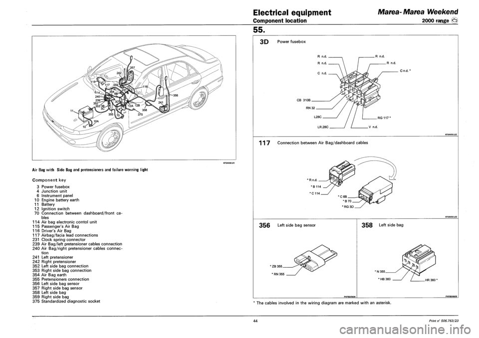
AIR BAG WITH SIDE BAG AND PRETENSIONERS AND FAILURE WARNING LIGHT
Component key
3 Power fusebox
4 Junction unit
6 Instrument panel
10 Engine battery earth
11 Battery
12 Ignition switch
70 Connection between dashboard/front ca
bles
114 Air bag electronic contol unit
115 Passenger's Air Bag
116 Driver's Air Bag
117 Airbag/facia lead connections
231 Clock spring connector
239 Air Bag/left pretensioner cables connection
240 Air Bag/right pretensioner cables connec
tion
241 Left pretensioner
242 Right pretensioner
352 Left side bag connection
353 Right side bag connection
354 Air Bag earth
355 Pretensioners connection
356 Left side bag sensor
357 Right side bag sensor
358 Left side bag
359 Right side bag
375 Standardized diagnostic socket
3D Power fusebox
R n.d.
R n.d.
Cn.d.*
RG 117'
LR 28C V n.d.
117 Connection between Air Bag/dashboard cables
* RG 3D
356 Left side bag sensor
' ZB 355
' RN 355
358 Left side bag
HR 360'
The cables involved in the wiring diagram are marked with an asterisk.
44 Print n° 506.763/23
Page 234 of 330
Electrical system
Component location
Marea-Marea Weekend
2000 range ©
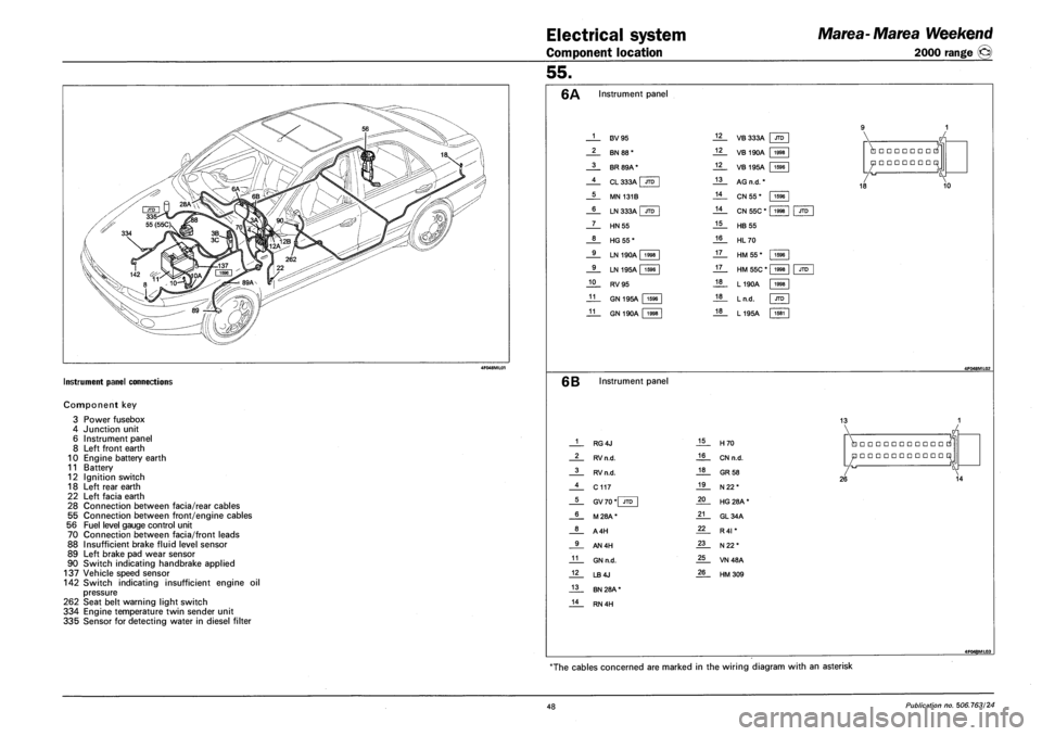
INSTRUMENT PANEL CONNECTIONS
Component key
3
4
6
8
10
11
12
18
22
28
55
56
70
88
89
90
Power fusebox
Junction unit
Instrument panel
Left front earth
Engine battery earth
Battery
Ignition switch
Left rear earth
Left facia earth
Connection between facia/rear cables
Connection between front/engine cables
Fuel level gauge control unit
Connection between facia/front leads
Insufficient brake fluid level sensor
Left brake pad wear sensor
Switch indicating handbrake applied
137 Vehicle speed sensor
142 Switch indicating insufficient engine oil
pressure
262 Seat belt warning light switch
334 Engine temperature twin sender unit
335 Sensor for detecting water in diesel filter
55.
Instrument panel
1
2
3
4
5
6
7
8
9
9
10
11
11
F3V95
BN 88*
BR 89A*
CL 333A I JTD
MN 131B
LN 333A | JTD
HN55
HG55*
LN 190A 1998
LN 195A | 1596
RV95
GN 195A 1596
GN 190A 1998
12
12
12
13
14
14
15
16
17
17
18
18
18
VB 333A JTD
VB 190A 1998
1596
1998
VB 195A | 1596
AG n.d. *
CN 55 *
CN 55C *
HB 55
HL70
HM 55*
HM 55C * |
L190A
Ln.d.
L195A
•••••••
•••••••
18 10
JTD
1596
1998
1998
JTD
1581
6B Instrument panel
13
1
2
3
4
5
6
8
9
11
12
13
14
RG4J
RV n.d.
RV n.d.
C117
GV 70 *| JTD
M28A*
A4H
AN4H
GN n.d.
LB4J
BN 28A *
RN 4H
15
16
18
19
20
21
22
23
25
26
H70
CN n.d.
GR 58
N22*
HG 28A *
GL34A
R4I *
N22*
VN48A
HM309
•••••••••••
•••••••••••
26 14
4F048ML03
The cables concerned are marked in the wiring diagram with an asterisk
48 Publication no. 506.763/24
Page 236 of 330
Electrical equipment
Component location
Marea-Marea Weekend
2000 range ®
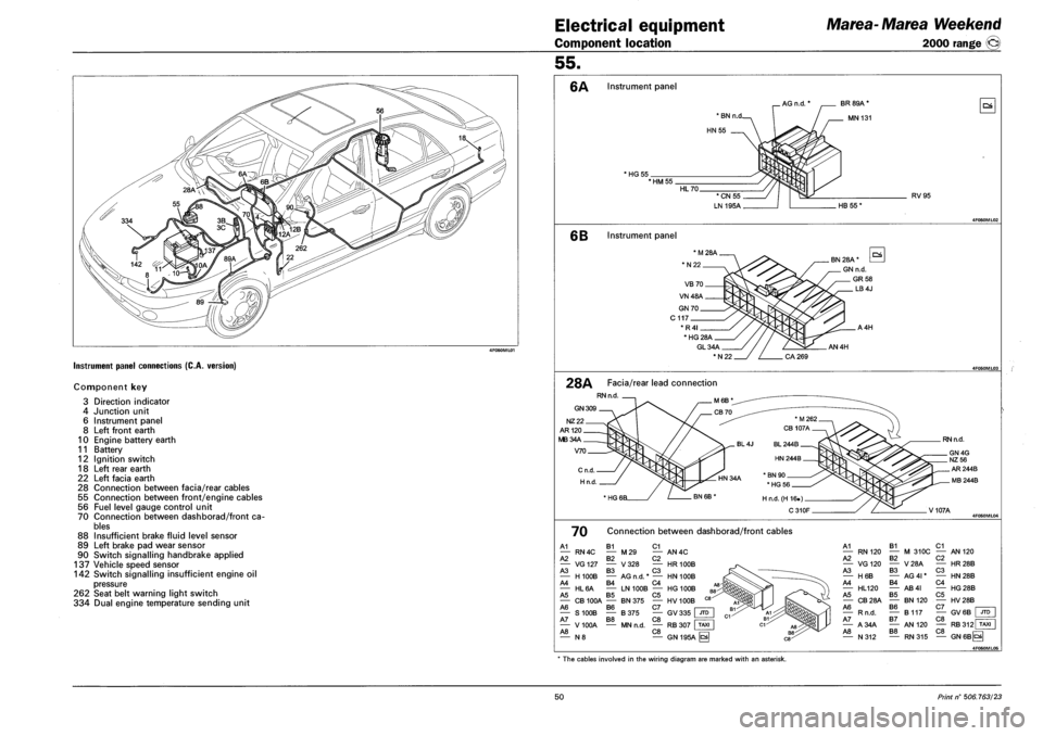
Instrument panel connections (C.A. version)
Component key
3 Direction indicator
4 Junction unit
6 Instrument panel
8 Left front earth
10 Engine battery earth
11 Battery
12 Ignition switch
18 Left rear earth
22 Left facia earth
28 Connection between facia/rear cables
55 Connection between front/engine cables
56 Fuel level gauge control unit
70 Connection between dashborad/front ca
bles
88 Insufficient brake fluid level sensor
89 Left brake pad wear sensor
90 Switch signalling handbrake applied
137 Vehicle speed sensor
142 Switch signalling insufficient engine oil
pressure
262 Seat belt warning light switch
334 Dual engine temperature sending unit
55.
6A Instrument panel
AG n.d. * BR 89A *
MN 131
HG 55 *HM55
RV95
6B Instrument panel
GL34A
*N22
AN4H
28A Facia/rear lead connection
RN n.d
GN 309
NZ22
AR120
MB34A
V70
RN n.d.
V107A
70 Connection between dashborad/front cables
A1 B1 C1 — RN4C — M29 — AN4C A2 B2 C2 — VG127 — V328 — HR100B A3 B3 C3 — H100B — AG n.d. * — HN 100B A4 B4 C4 — HL6A — LN 100B — HG 100B A5 B5 C5 — CB 100A — BN 375 — HV 100B A6 B6 C7 | — S100B — B375 — GV335 JTD A7 B8 C8 • — V 100A — MN n.d. — RB 307 I TAXI A8 C8 — N 8 — GN 195A ^
A1 — RN120 A2 — VG120 A3 — H6B A4 — HL120 A5 — CB28A A6 — Rn.d. A7 — A34A A8 — N312
B1 — M 310C B2 — V28A B3 — AG 41* B4 — AB4I B5 — BN120 B6 — B117 B7 — AN 120 B8
C1 — AN 120 C2 — HR28B C3 — HN28B C4 — HG28B C5 — HV28B C7 — GV6B C8 JTD
C8 RB312 TAXI
RN315 — GN6BCS
4F060ML05
* The cables involved in the wiring diagram are marked with an asterisk.
50 Print n° 506.763/23
Page 253 of 330
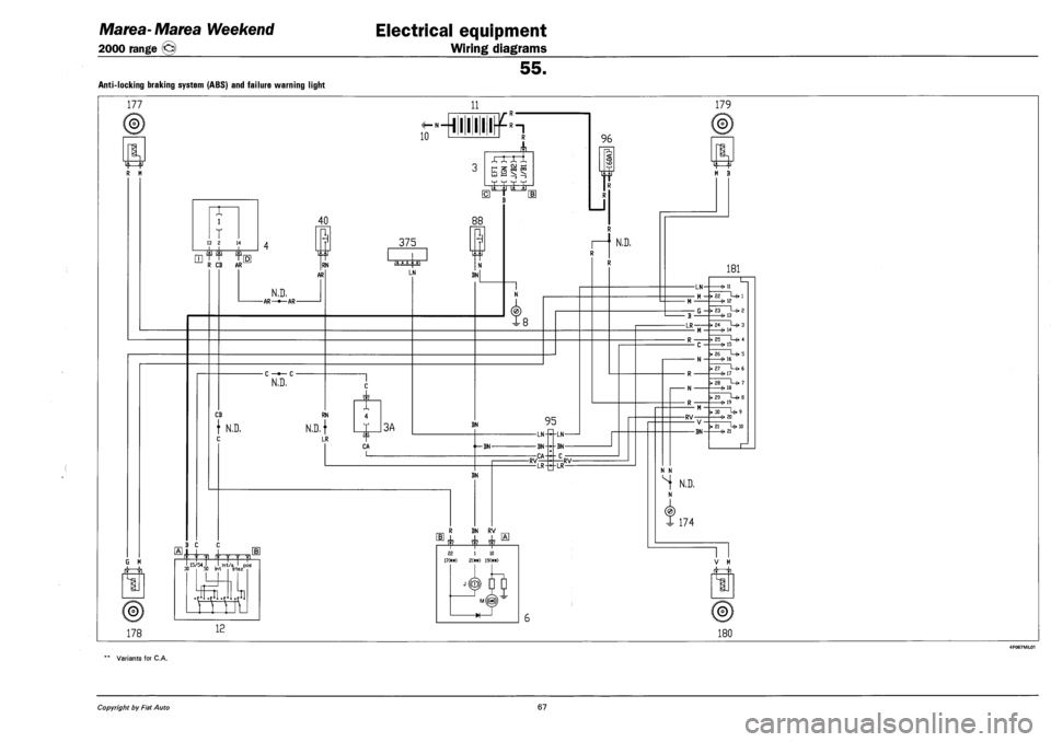
Marea- Marea Weekend
2000 range ©
Electrical equipment
Wiring diagrams
55.
Anti-locking braking system (ABS) and failure warning light
177
if~~fr
R M
G M
©j
178
11
10 1 1 R
XXX „ _ Rl -
h & s §
1
T 13 2 14
R CB AR
40 88
mi
RN
AR
375
N.D. -AR-*—AR-
C —•— C •
N.D.
LN
CB RN
} N.D, N.D.}
LR
1
T
k i 3A
BN
96
p1. <: CD
R
rl
N.D.
N
3-8
BN 95
CA |_ ,^BN-
BN
-RV-
LN--LN
BN--BN
CA-•c LR--IR -RV-
B C
I 15/54 I I ht/o I
.1]
' 15/54 I , I Int/a pos 30 50 Irvt s-tazK
12
R BN RV
Jf. sj2 E|L
22 1 LO 17(*«) 2(*«) 19C**)
179
M B
181
-LN-
- M -
- B •
-LR-
G ->
-RV-• V-
-BN-
—(• 11
"ii L-«. l —e-13
-fr 13
"24 L-(. 3 (• 14
"Ii L-«. 4 15
"ii !-«• 5 16 ~27 L-0 6 6- 17
"is L-> 7 —e- is
"ii L-«. s 6- 19 30U- 9 20
"ii U. io O 21
N N
^ N.D.
N
X 174
V M
©;
180
Variants for C.A.
Copyright by Fiat Auto 67
Page 254 of 330
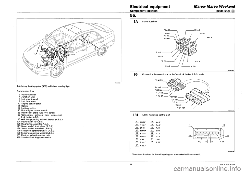
Electrical equipment
Component location
Marea-Marea Weekend
2000 range ©
55.
ANTI-LOCKING BRAKING SYSTEM (ABS) AND FAILURE WARNING LIGHT
Component key
3 Power fusebox
4 Junction unit:
6 Instrument panel
8 Left front earth
10 Engine battery earth
11 Battery
12 Ignition switch
40 Brake lights control switch
88 Insufficient brake fluid level sensor
95 Connection between front cables/anti-
lock brakes A.B.S.
96 60A fuse protecting anti-lock brakes (A.B.S.)
174 Power earth for A.B.S.
176 Diagnostic socket for A.B.S.
177 Sensor on left front wheel (A.B.S.)
178 Sensor on left rear wheel (AB.S.)
179 Sensor on right front wheel (AB.S.)
180 Sensor on right rear wheel (AB.S.)
181 Electro-hydraulic control unit
375 Standardized diagnostic socket
3A Power fusebox
*CA95 CB n.d.
R n.d.
M n.d.
X n.d
.VN127
AR n.d.
.C n.d.
C n.d M n.d.
95 Connection between front cables/anti-lock brakes A.B.S. leads
LN 375
BN n.d.
*CA3A
BN 181
*CN 181
1 81 A.B.S. hydraulic control unit
9 M 180* 18 N n.d. *
10 V180* 19 R n.d. *
11 LN 95 20 RV95*
12 M 179* 21 BN 95*
13 B 179* 22 M 178*
14 M 177* 23 G 178*
15 C95* 24 LR 95*
16 N n.d. * 25 R 177*
17 Rn.d.*
4FQ68ML04
The cables involved in the wiring diagram are marked with an asterisk.
68 Print n° 506.763/23
Page 255 of 330
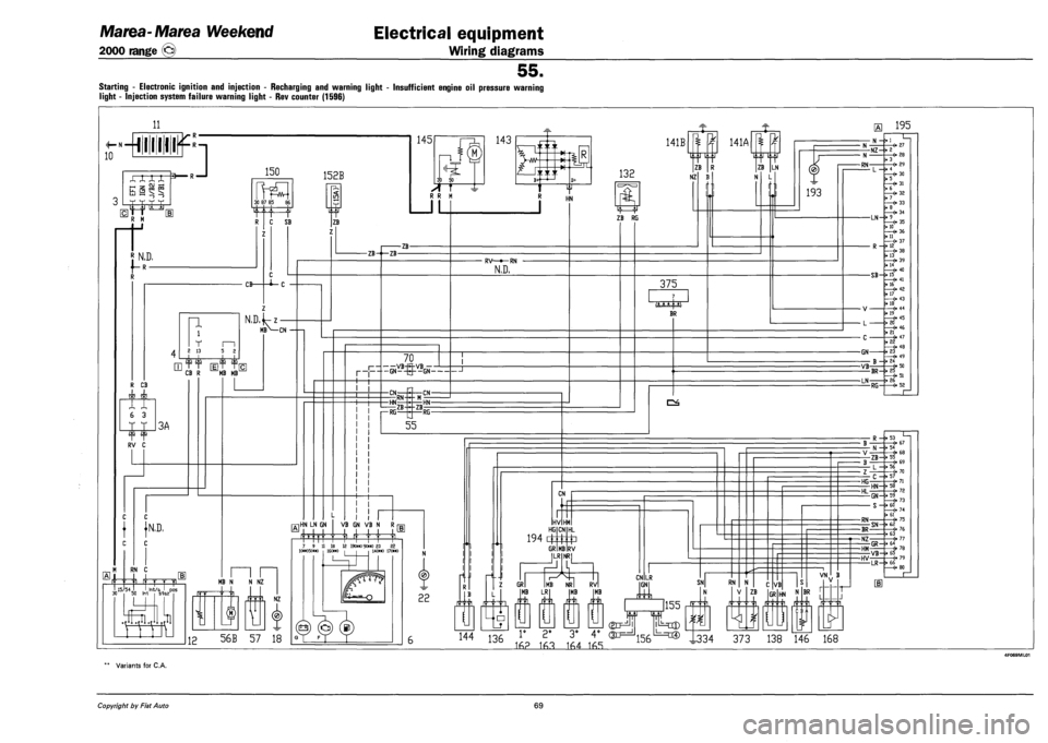
Marea-Marea Weekend
2000 range ©
Electrical equipment
Wiring diagrams
55.
Starting - Electronic ignition and injection - Recharging and warning light - Insufficient engine oil pressure warning
light - Injection system failure warning light - Rev counter (1596)
11
N «
10 -•miliums
XX XX
l-H
h §
3 R —I
'jj it Itr
150
E1TT R M
rt
30 87 85 8£
i N.D,
f-R-
152B
R C SB
Z
p, <: in
ZB
n i
T m 2 13 5 2
CB-
N,D,
c
•i-c
141B
132 ZB
NZ
m>— MBN—CN
CB R MB MB
RV C
}N,D,
RN C
J I -|- -|i r—pji I 15/54 I Irrt/a J pos s-taz
M
-IB-
IE HN LN GN
50 Irrt
,11
MB N N NZ
I NZ
12 56B 57 18
-ZB--ZB-
70 i VB-R-VB 1—
P- — GN--Q--GN
-CN
r—RG-
RN -CN-
RV—»—RN
N,D,
Z7T
ZB HN-
-RG-
55
VB GN VB N R i
7 9 11 18 12 19(m> 9(>«) 23 22 N
22
rl.l
(J
H..I
ZB RG
141A
375
BR
CN
HV HM HG
194 4
GR
CN
MB
HL
P RV ILR
GR MB LR
NRI
CN LR
-31.
N
ZB LN
L
193
U
MB RVI MB GN SNl RN
144 136 1' 2* 3* 4° 0X3==^^ lJ=c® I334 373 138 146 168
155
1
16? 163 164 165
ZB VB
GR N BR
VN
r
"N 111 L
L^
H 195
•N--I
- N
-RN-
-NZ--2
L ->
3
4
5
6
7
8
LN-M
10
11
12
13
14
15
16
17
R -•
-SB--
- V¬
- L -
- C -
-GN-
-VB B -•
-BR--
-LN-RG-
-0 27 3 28
<• 29
30
31
32
33
34
35
36
37
38
39
40
41
42
43 18 —(• 44 19 —(- 45 20 —(• 46 21 —O 47 22 —(• 48 23 49 24 -«• 50 25 . 51 26 —(• 52
R ->
-ZB--
• L — f>
-HG-C--
-HL-HN-
-RN-
-BR
-NZ
-HM GR--
-HV
53 67 54 -O 68 55 69 56 > 70 57 71 58 —«• 72
, 73 -> 60
75
SN+ii76 63 —«• 77 64 , -6-78 VB-r> &5 6-79 LR--«
Variants for C.A.
Copyright by Fiat Auto 69
Page 256 of 330
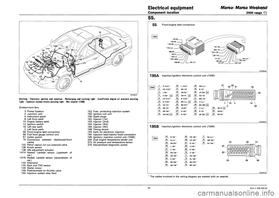
Electrical equipment
Component location
Marea-Marea Weekend
2000 range ©
55.
Starting - Electronic ignition and injection - Recharging and warning light
light - Injection system failure warning light - Rev counter (1596)
Insufficient engine oil pressure warning
Component key
3 Power fusebox
4 Junction unit:
6 Instrument panel
8 Left front earth
10 Engine battery earth
12 Ignition switch
18 Left rear earth
2 Left facia earth
55 Front/engine lead connection
56 Fuel level gauge control unit
57 Inertia switch
70 Connection between dashborad/front
cables
132 Petrol vapour cut out solenoid valve
136 Knock sensor
138 Idle adjustment actuator
141A Heated Lambda sensor (upstream of
cat.)
141 B Heated Lambda sensor (downstream of
cat.)
143 Alternator
144 Rpm and TDC sensor
145 Starter motor
146 Potentiometer on throttle valve
150 Injection system relay feed
152 Fuse protecting injection system
155 Ignition coil unit
156 Spark plugs
162 Injector (1st)
163 Injector (2nd)
164 Injector (3rd)
165 Injector (4th)
168 Timing sensor
193 Earth for electronic injection
194 Injection lead/injector braid connection
195 Ignition/ injection control unit (1596)
334 Dual engine temperature sender unit
373 Air pressure and temperature sensor
375 Standardized diagnostic socket
55 Front/engine lead connection
1596
CN6A.
HG6A.
* HN 6A
1 CN n.d.
MB6A.
NZ8_
* ZB n.d
*RG195A_
HM6A
CN n.d. HN 143 *
HG 142
1 95A Injection/ignition electronic control unit (1596)
1596 1 N 141A* 20 L 141A* 29 RN n.d. *
2 NZ141B* 21 BN 127 35 B 127
4 L6A* 23 GN 6A* 36 LR252 [c*
5 V252 0 23 GN70 0 40 AG 127
9 LN 141A* 24 B141B* 41 MG 127
12 R 141B* 25 BR n.d. 0 44 Vn.d.*
13 GV131 25 BR 375 * 46 BG 268 [a
14 AB 127 26 LN6A* 47 C n.d. *
15 SB 150* 27 N 193* 48 S 127
16 GN 252 [cal 28 N 193* 49 NZ252
27 282,9 41 52
O I I I I I I -r-r-r'n , , r'l -r-
rrrri '/ 1 1 1 1 1 1 1 1 1 1 1 \1 L/-HJ 'A i I I i i ,I
40
1 95B Injection/ignition electronic control unit (1596)
1596 53 R144* 65 VB 138* JL. NZn.d. *
54 N n.d. * 66 LR 155 * _ZL HM194*
55 ZB 278 * 67 B 144* _7JL HV194*
56 L136* 68 V278*
57 C138* 69 B 168*
58 HN 138* 70 Z136*
59 GN 155 * 71 HG 194 *
60 S 146* 72 HL194*
62 SN 339 * 75 RN 278 *
64 GR138* 76 BR 146 *
74
67-Jf Mill i i r r-l I I I
60-
IE
L -j |l
53 59
The cables involved in the wiring diagram are marked with an asterisk.
70 Print n° 506.763/23
Page 257 of 330
Marea-Marea Weekend
2000 range (§)
Electrical equipment
Wiring diagrams
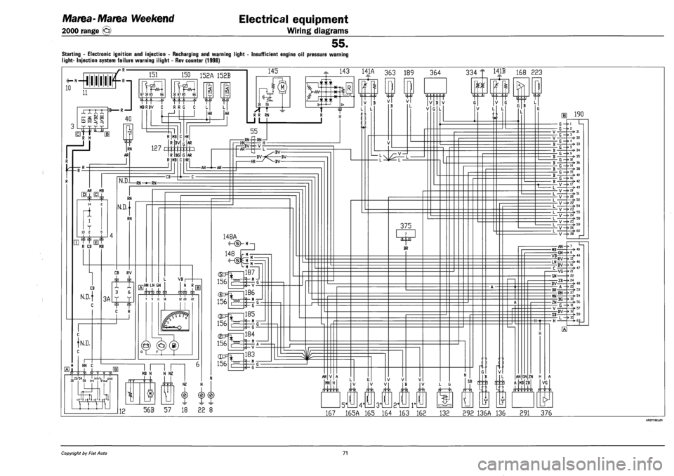
55.
STARTING - ELECTRONIC IGNITION AND INJECTION - RECHARGING AND WARNING LIGHT - INSUFFICIENT ENGINE OIL PRESSURE WARNING
LIGHT- INJECTION SYSTEM FAILURE WARNING ILIGHT - REV COUNTER (1998)
^—hi 11111
168 223
56B 57 18 22 8 167 165A 165 164 163 162 132 292 136A 136 291 376
Copyright by Fiat Auto 71