Compressor FIAT MAREA 2000 1.G Workshop Manual
[x] Cancel search | Manufacturer: FIAT, Model Year: 2000, Model line: MAREA, Model: FIAT MAREA 2000 1.GPages: 330
Page 38 of 330
Marea- Marea Weekend Technical Data
2000 range (§) Engine: supercharging
OO.io
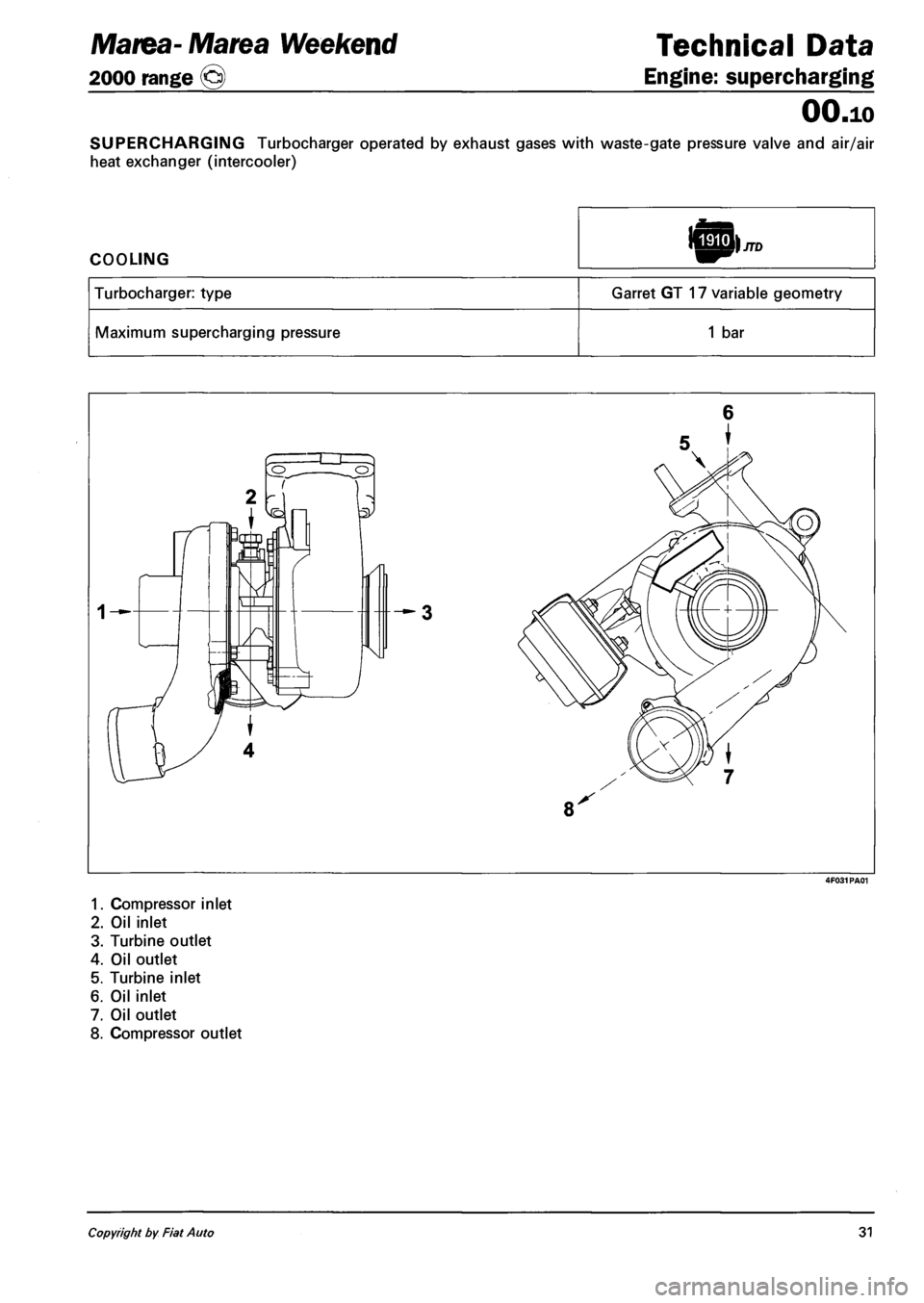
SUPERCHARGING Turbocharger operated by exhaust gases with waste-gate pressure valve and air/air
heat exchanger (intercooler)
COOLING
Turbocharger: type Garret GT 17 variable geometry
Maximum supercharging pressure 1 bar
6
5
1. Compressor inlet
2. Oil inlet
3. Turbine outlet
4. Oil outlet
5. Turbine inlet
6. Oil inlet
7. Oil outlet
8. Compressor outlet
Copyright by Fiat Auto 31
Page 91 of 330
![FIAT MAREA 2000 1.G Workshop Manual Marea-Marea Weekend 9]
2000 range (j§)
I) JTD
Fuel feed system
Engine
10.
Exhaust fumes control
Through this function the injection control unit limits any exhaust fumes that could be produce FIAT MAREA 2000 1.G Workshop Manual Marea-Marea Weekend 9]
2000 range (j§)
I) JTD
Fuel feed system
Engine
10.
Exhaust fumes control
Through this function the injection control unit limits any exhaust fumes that could be produce](/img/10/4653/w960_4653-90.png)
Marea-Marea Weekend 9]
2000 range (j§)
I) JTD
Fuel feed system
Engine
10.
Exhaust fumes control
Through this function the injection control unit limits any exhaust fumes that could be produced during
transition speeds.
To satisy these requirements the control unit processes the signals supplied by the accelerator pedal po
tentiometer, the rpm sensor and the air flow meter and controls the fuel pressure regulator and the injec
tors to meter the correct amount of fuel to inject.
Exhaust gas recirculation control
On the basis of the signals supplied by the rpm sensor, intake air quantity sensor, engine coolant tempe
rature sensor and accelerator pedal position sensor, the control unit calculates the operating times for the
EGR valve so that the exhaust gases are partly recirculated in certain engine operating conditions in line
with Euro 3 pollution control standards.
Air conditioning system engagement control
The injection control unit manages the operation of the air conditioning system compressor electro
magnet coupling following a logic aimed at preventing operating conditions that would adversely affect
engine performance.
- When the compressor is switched on the injection control unit increases the quantity of fuel during
idling to allow the engine to adjust to the increased power requirements and momentarily interrupts the
supply to the compressor in high engine power requirement conditions (strong acceleration).
Engine immobilizer function control
The system is equipped with an engine immobilizer function. This function is achieved through the pre
sence of a specific control unit (Fiat CODE), capable of conversing with the injection control unit and an
electronic key with a special transmitter for sending a recognition code.
Each time the key is turned to the OFF position, the Fiat CODE system completely deactivates the injecti
on control unit.
When the key is turned to the ON position the following operations take place, in order:
1. the injection control unit (whose memory contains a secret code) sends the Fiat CODE control unit a
request to send the secret code to deactivate the immobilizer functions;
2. the Fiat CODE control unit responds by only sending the secret code after, in turn, having received the
recognition code transmitted by the ignition key;
3. the recognition of the secret code allows the deactivation of the injection control unit immobilizer func
tion and its normal operation.
Autodiagnosis
The complete electronic fault diagnosis of the injection system is carried out by connecting the special
equipment (EXAMINER or EXAMINER PLUS) to the standardized diagnostic socket (EOBD).
The system is also equipped with a self-diagnostic function which recognizes, memorizes and signals any
faults.
If a fault is detected in the sensors or actuators, the recovery strategy is immediately activated in order to
ensure that the engine functions at an acceptable level. The vehicle can be driven to a service centre for
the appropriate repairs to be carried out.
Copyright by Fiat Auto 5
Page 93 of 330
Marea- Marea Weekend 9 ™
2000 range ©
Engine
Fuel feed system
10.
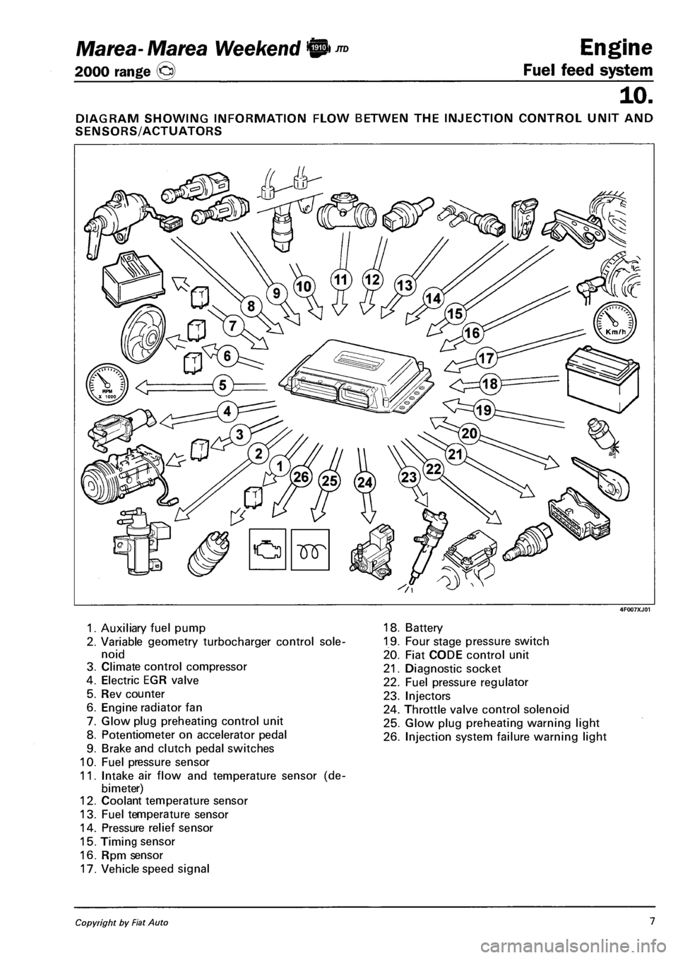
DIAGRAM SHOWING INFORMATION FLOW BETWEN THE INJECTION CONTROL UNIT AND
SENSORS/ACTUATORS
1. Auxiliary fuel pump
2. Variable geometry turbocharger control sole
noid
3. Climate control compressor
4. Electric EGR valve
5. Rev counter
6. Engine radiator fan
7. Glow plug preheating control unit
8. Potentiometer on accelerator pedal
9. Brake and clutch pedal switches
10. Fuel pressure sensor
11. Intake air flow and temperature sensor (de-
bimeter)
12. Coolant temperature sensor
13. Fuel temperature sensor
14. Pressure relief sensor
15. Timing sensor
16. Rpm sensor
17. Vehicle speed signal
18. Battery
19. Four stage pressure switch
20. Fiat CODE control unit
21. Diagnostic socket
22. Fuel pressure regulator
23. Injectors
24. Throttle valve control solenoid
25. Glow plug preheating warning light
26. Injection system failure warning light
Copyright by Fiat Auto 1
Page 111 of 330
Marea- Marea Weekend 9
2000 range ©
Engine
Fuel feed system
10.
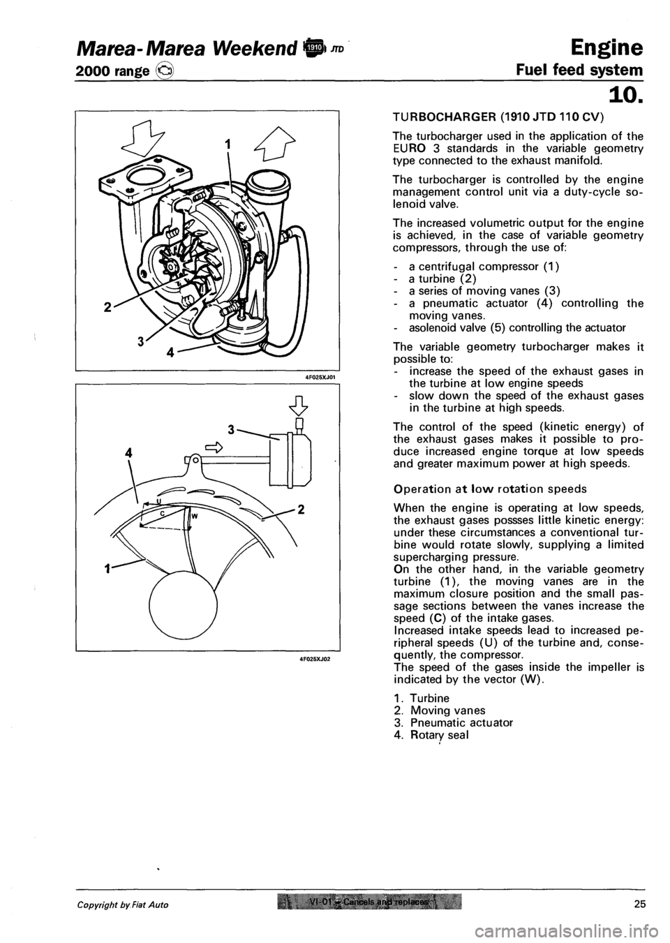
TURBOCHARGER (1910 JTD 110 CV)
The turbocharger used in the application of the
EURO 3 standards in the variable geometry
type connected to the exhaust manifold.
The turbocharger is controlled by the engine
management control unit via a duty-cycle so
lenoid valve.
The increased volumetric output for the engine
is achieved, in the case of variable geometry
compressors, through the use of:
- a centrifugal compressor (1)
- a turbine (2)
- a series of moving vanes (3)
- a pneumatic actuator (4) controlling the
moving vanes.
- asolenoid valve (5) controlling the actuator
The variable geometry turbocharger makes it
possible to:
- increase the speed of the exhaust gases in
the turbine at low engine speeds
- slow down the speed of the exhaust gases
in the turbine at high speeds.
The control of the speed (kinetic energy) of
the exhaust gases makes it possible to pro
duce increased engine torque at low speeds
and greater maximum power at high speeds.
Operation at low rotation speeds
When the engine is operating at low speeds,
the exhaust gases possses little kinetic energy:
under these circumstances a conventional tur
bine would rotate slowly, supplying a limited
supercharging pressure.
On the other hand, in the variable geometry
turbine (1), the moving vanes are in the
maximum closure position and the small pas
sage sections between the vanes increase the
speed (C) of the intake gases.
Increased intake speeds lead to increased pe
ripheral speeds (U) of the turbine and, conse
quently, the compressor.
The speed of the gases inside the impeller is
indicated by the vector (W).
1. Turbine
2. Moving vanes
3. Pneumatic actuator
4. Rotary seal
Copyright by Fiat Auto r VI-01-Cancels arwl replaces.25
Page 125 of 330
Marea- Marea Weekend
2000 range CJ
Auxiliary Units
Index
Compressor ( 1596 engine)
Compressor ( 1910 JTD)
Compressor ( 1998 engine)
Specifications
50
page
1
2
3
4
FOR ANYTHING NOT DEALT WITH,
REFER TO THE BASIC MANUAL, SECTION 50.
Copyright by Fiat Auto
Page 126 of 330
Marea- Marea Weekend
2000 range ©
Auxiliary Units
Climate control
50
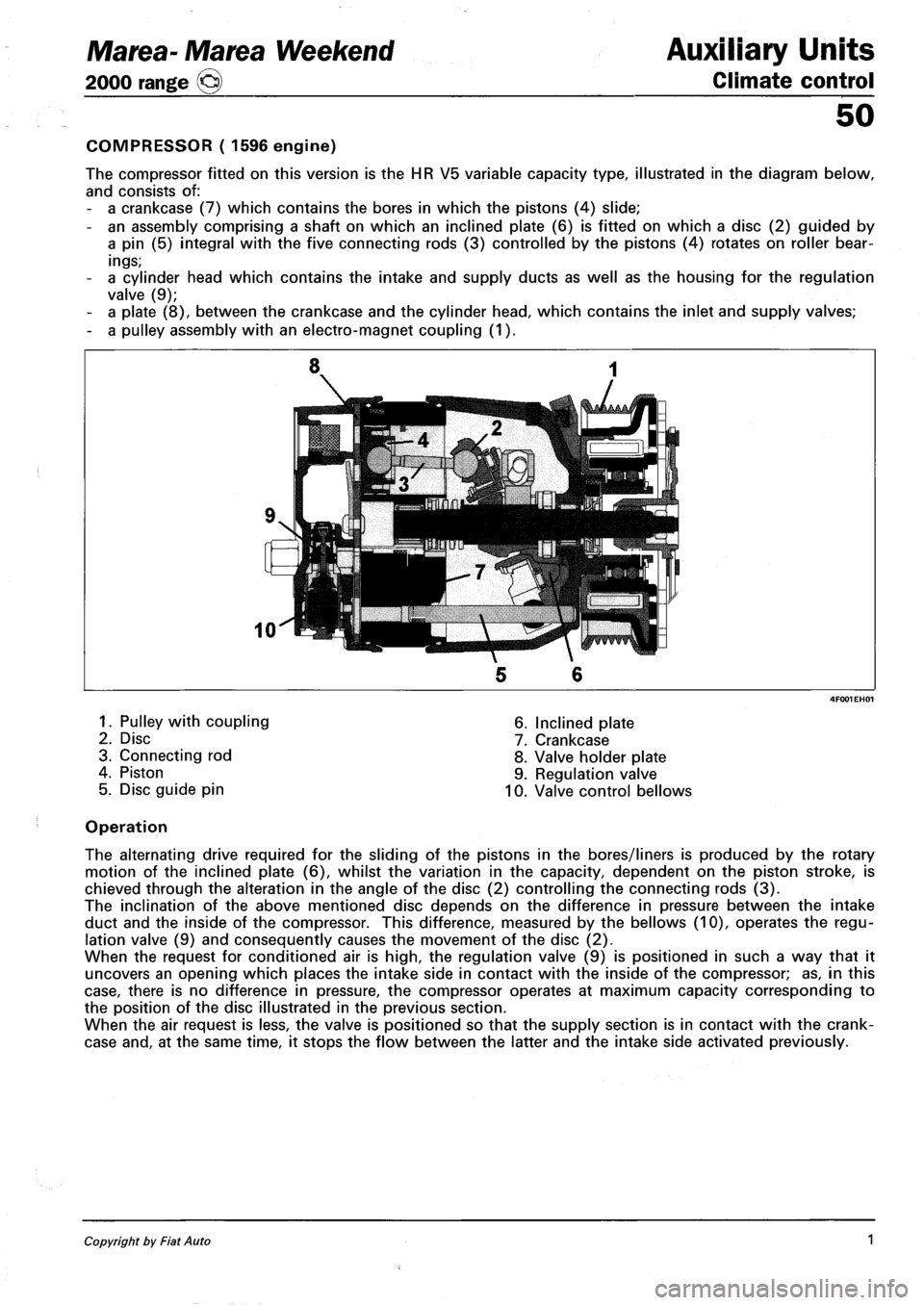
COMPRESSOR ( 1596 engine)
The compressor fitted on this version is the HR V5 variable capacity type, illustrated in the diagram below,
and consists of:
- a crankcase (7) which contains the bores in which the pistons (4) slide;
- an assembly comprising a shaft on which an inclined plate (6) is fitted on which a disc (2) guided by
a pin (5) integral with the five connecting rods (3) controlled by the pistons (4) rotates on roller bear
ings;
- a cylinder head which contains the intake and supply ducts as well as the housing for the regulation
valve (9);
- a plate (8), between the crankcase and the cylinder head, which contains the inlet and supply valves;
- a pulley assembly with an electro-magnet coupling (1).
1. Pulley with coupling
2. Disc
3. Connecting rod
4. Piston
5. Disc guide pin
6. Inclined plate
7. Crankcase
8. Valve holder plate
9. Regulation valve
10. Valve control bellows
Operation
The alternating drive required for the sliding of the pistons in the bores/liners is produced by the rotary
motion of the inclined plate (6), whilst the variation in the capacity, dependent on the piston stroke, is
chieved through the alteration in the angle of the disc (2) controlling the connecting rods (3).
The inclination of the above mentioned disc depends on the difference in pressure between the intake
duct and the inside of the compressor. This difference, measured by the bellows (10), operates the regu
lation valve (9) and consequently causes the movement of the disc (2).
When the request for conditioned air is high, the regulation valve (9) is positioned in such a way that it
uncovers an opening which places the intake side in contact with the inside of the compressor; as, in this
case, there is no difference in pressure, the compressor operates at maximum capacity corresponding to
the position of the disc illustrated in the previous section.
When the air request is less, the valve is positioned so that the supply section is in contact with the crank
case and, at the same time, it stops the flow between the latter and the intake side activated previously.
Copyright by Fiat Auto 1
Page 127 of 330
Auxiliary Units
Climate control
Marea-Marea Weekend
2000 range O
50
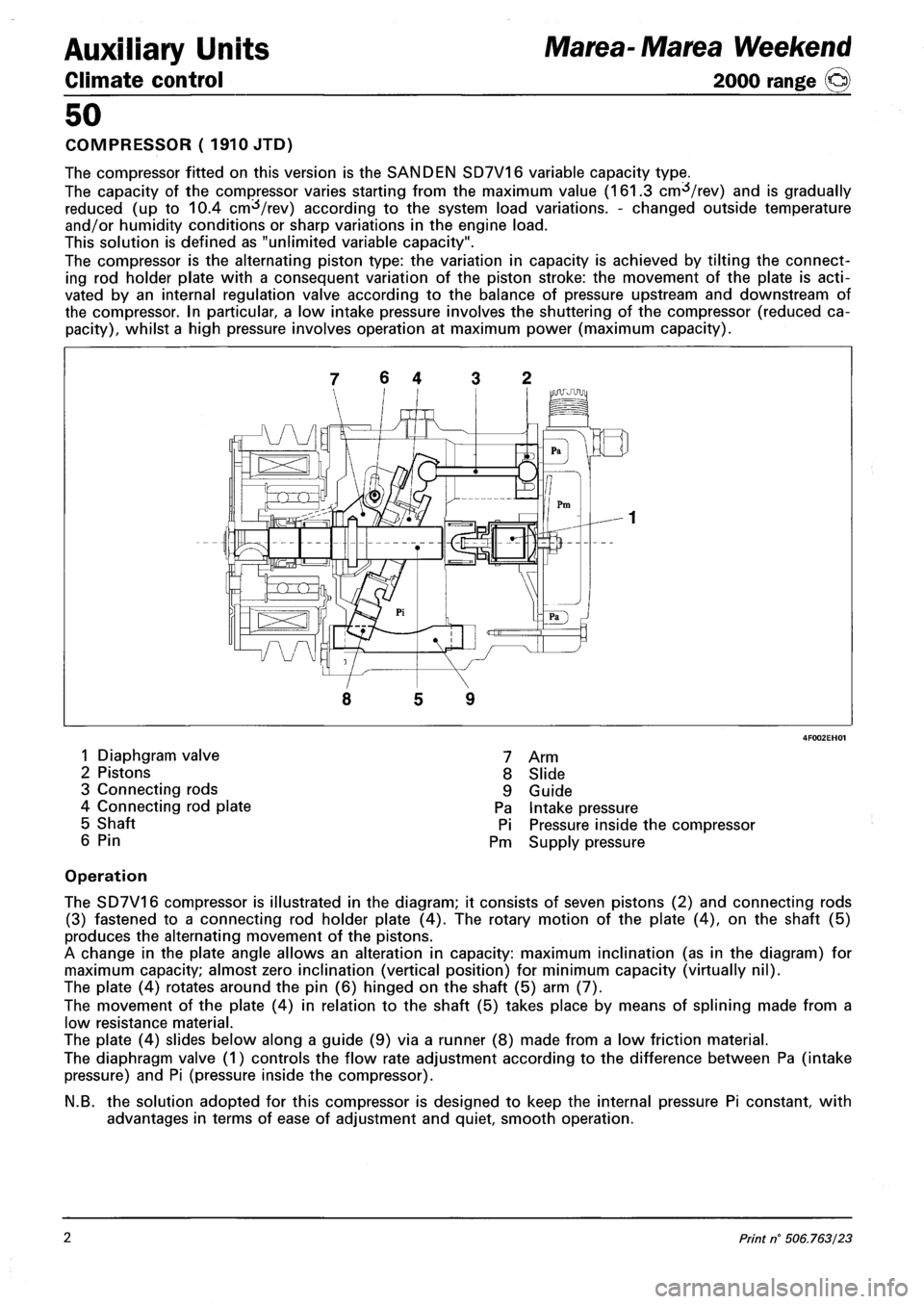
COMPRESSOR (1910 JTD)
The compressor fitted on this version is the SANDEN SD7V16 variable capacity type.
The capacity of the compressor varies starting from the maximum value (161.3 cm^/rev) and is gradually
reduced (up to 10.4 cm^/rev) according to the system load variations. - changed outside temperature
and/or humidity conditions or sharp variations in the engine load.
This solution is defined as "unlimited variable capacity".
The compressor is the alternating piston type: the variation in capacity is achieved by tilting the connect
ing rod holder plate with a consequent variation of the piston stroke: the movement of the plate is acti
vated by an internal regulation valve according to the balance of pressure upstream and downstream of
the compressor. In particular, a low intake pressure involves the shuttering of the compressor (reduced ca
pacity), whilst a high pressure involves operation at maximum power (maximum capacity).
7 6 4 3 2
5 9
1 Diaphgram valve
2 Pistons
3 Connecting rods
4 Connecting rod plate
5 Shaft
6 Pin
7 Arm
8 Slide
9 Guide
Pa Intake pressure
Pi Pressure inside the compressor
Pm Supply pressure
Operation
The SD7V16 compressor is illustrated in the diagram; it consists of seven pistons (2) and connecting rods
(3) fastened to a connecting rod holder plate (4). The rotary motion of the plate (4), on the shaft (5)
produces the alternating movement of the pistons.
A change in the plate angle allows an alteration in capacity: maximum inclination (as in the diagram) for
maximum capacity; almost zero inclination (vertical position) for minimum capacity (virtually nil).
The plate (4) rotates around the pin (6) hinged on the shaft (5) arm (7).
The movement of the plate (4) in relation to the shaft (5) takes place by means of splining made from a
low resistance material.
The plate (4) slides below along a guide (9) via a runner (8) made from a low friction material.
The diaphragm valve (1) controls the flow rate adjustment according to the difference between Pa (intake
pressure) and Pi (pressure inside the compressor).
N.B. the solution adopted for this compressor is designed to keep the internal pressure Pi constant, with
advantages in terms of ease of adjustment and quiet, smooth operation.
2 Print n° 506.763/23
Page 128 of 330
Marea-Marea Weekend
2000 range ©)
Auxiliary Units
Climate control
50
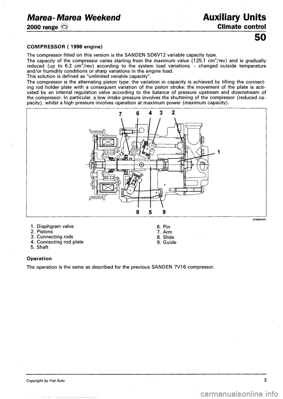
COMPRESSOR ( 1998 engine)
The compressor fitted on this version is the SANDEN SD6V12 variable capacity type.
The capacity of the compressor varies starting from the maximum value (125.1 cnrfVrev) and is gradually
reduced (up to 6.2 cm /rev) according to the system load variations. - changed outside temperature
and/or humidity conditions or sharp variations in the engine load.
This solution is defined as "unlimited variable capacity".
The compressor is the alternating piston type: the variation in capacity is achieved by tilting the connect
ing rod holder plate with a consequent variation of the piston stroke: the movement of the plate is acti
vated by an internal regulation valve according to the balance of pressure upstream and downstream of
the compressor. In particular a low intake pressure involves the shuttering of the compressor (reduced ca
pacity), whilst a high pressure involves operation at maximum power (maximum capacity).
1. Diaphgram valve
2. Pistons
3. Connecting rods
4. Connecting rod plate
5. Shaft
6. Pin
7. Arm
8. Slide
9. Guide
Operation
The operation is the same as described for the previous SANDEN 7V16 compressor.
Copyright by Fiat Auto 3
Page 129 of 330
Auxiliary Units
Climate control
50
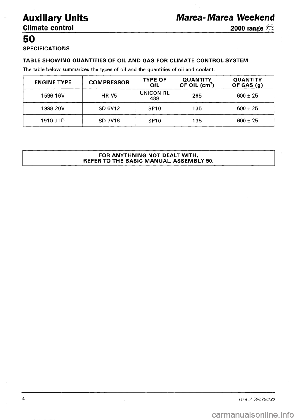
SPECIFICATIONS
TABLE SHOWING QUANTITIES OF OIL AND GAS FOR CLIMATE CONTROL SYSTEM
The table below summarizes the types of oil and the quantities of oil and coolant.
ENGINE TYPE COMPRESSOR TYPE OF
OIL
QUANTITY
OF OIL (cm3)
QUANTITY
OF GAS (g)
1596 16V HR V5 UNICON RL
488 265 600 ± 25
1998 20V SD6V12 SP10 135 600 ± 25
1910 JTD SD 7V16 SP10 135 600 ± 25
FOR ANYTHNING NOT DEALT WITH,
REFER TO THE BASIC MANUAL, ASSEMBLY 50.
Marea-Marea Weekend
2000 range ©
4 Print n' 506.763/23
Page 138 of 330
Electrical system
Protection and security devices
Marea-Marea Weekend
2000 range Q
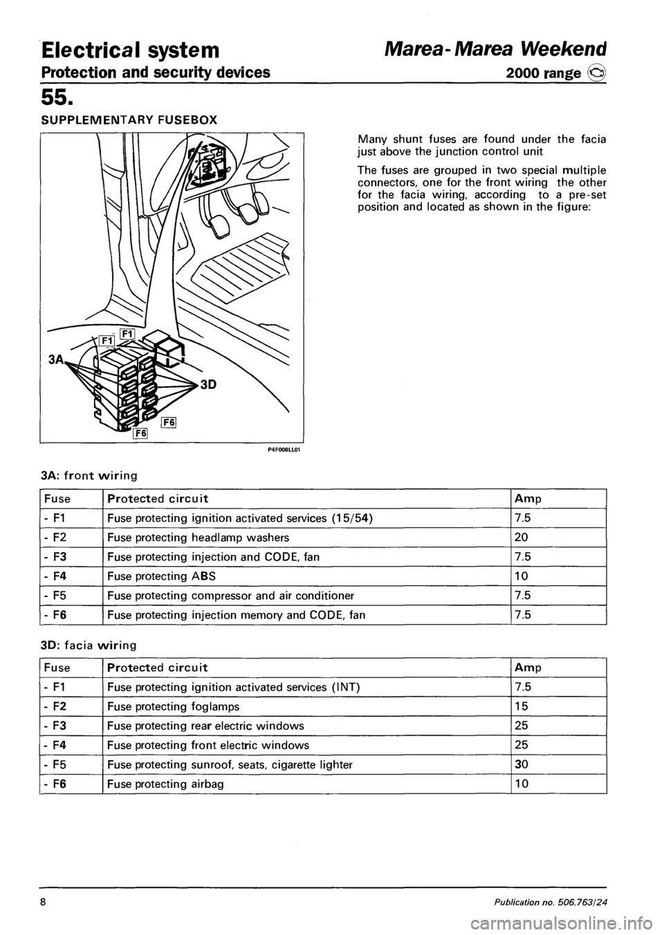
55.
SUPPLEMENTARY FUSEBOX
Many shunt fuses are found under the facia
just above the junction control unit
The fuses are grouped in two special multiple
connectors, one for the front wiring the other
for the facia wiring, according to a pre-set
position and located as shown in the figure:
3A: front wiring
Fuse Protected circuit Amp
- F1 Fuse protecting ignition activated services (15/54) 7.5
- F2 Fuse protecting headlamp washers 20
- F3 Fuse protecting injection and CODE, fan 7.5
- F4 Fuse protecting ABS 10
- F5 Fuse protecting compressor and air conditioner 7.5
- F6 Fuse protecting injection memory and CODE, fan 7.5
3D: facia wiring
Fuse Protected circuit Amp
- F1 Fuse protecting ignition activated services (INT) 7.5
- F2 Fuse protecting foglamps 15
- F3 Fuse protecting rear electric windows 25
- F4 Fuse protecting front electric windows 25
- F5 Fuse protecting sunroof, seats, cigarette lighter 30
- F6 Fuse protecting airbag 10
8 Publication no. 506.763/24