Gauge FIAT MAREA 2000 1.G Workshop Manual
[x] Cancel search | Manufacturer: FIAT, Model Year: 2000, Model line: MAREA, Model: FIAT MAREA 2000 1.GPages: 330
Page 86 of 330
Marea- Marea Weekend 9 \) JTD
2000 range O
Engine
Index
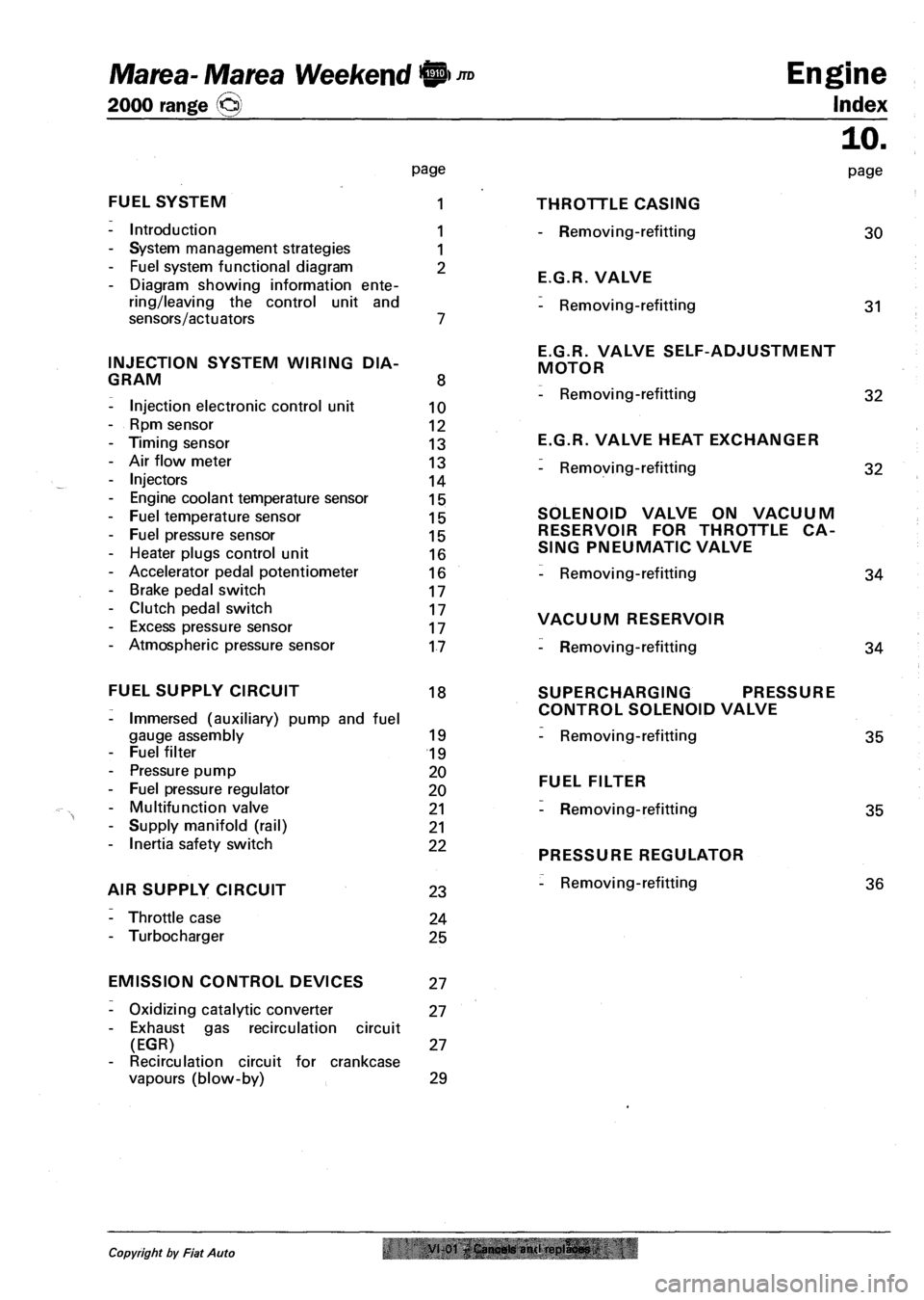
FUEL SYSTEM
- Introduction
- System management strategies
- Fuel system functional diagram
- Diagram showing information ente
ring/leaving the control unit and
sensors/actuators
INJECTION SYSTEM WIRING DIA
GRAM
- Injection electronic control unit
- Rpm sensor
- Timing sensor
- Air flow meter
- Injectors
- Engine coolant temperature sensor
- Fuel temperature sensor
- Fuel pressure sensor
- Heater plugs control unit
- Accelerator pedal potentiometer
- Brake pedal switch
- Clutch pedal switch
- Excess pressure sensor
- Atmospheric pressure sensor
page
1
1
1
2
8
10
12
13
13
14
15
15
15
16
16
17
17
17
17
THROTTLE CASING
- Removing-refitting
E.G.R. VALVE
- Removing-refitting
E.G.R. VALVE SELF-ADJUSTMENT
MOTOR
- Removing-refitting
E.G.R. VALVE HEAT EXCHANGER
- Removing-refitting
SOLENOID VALVE ON VACUUM
RESERVOIR FOR THROTTLE CA
SING PNEUMATIC VALVE
- Removing-refitting
VACUUM RESERVOIR
- Removing-refitting
10.
page
30
31
32
32
34
34
FUEL SUPPLY CIRCUIT 18
- Immersed (auxiliary) pump and fuel
gauge assembly 19
- Fuel filter 19
- Pressure pump 20
- Fuel pressure regulator 20
- Multifunction valve 21
- Supply manifold (rail) 21
- Inertia safety switch 22
AIR SUPPLY CIRCUIT 23
- Throttle case 24
- Turbocharger 25
SUPERCHARGING PRESSURE
CONTROL SOLENOID VALVE
- Removing-refitting 35
FUEL FILTER
- Removing-refitting 35
PRESSURE REGULATOR
- Removing-refitting 36
EMISSION CONTROL DEVICES 27
- Oxidizing catalytic converter 27
- Exhaust gas recirculation circuit
(EGR) 27
- Recirculation circuit for crankcase
vapours (blow-by) 29
Copyright by Fiat Auto VI 01 Cancels anil replaces
Page 104 of 330
Engine
Fuel feed system
JTD Marea- Marea Weekend 0
2000 range ©
10.
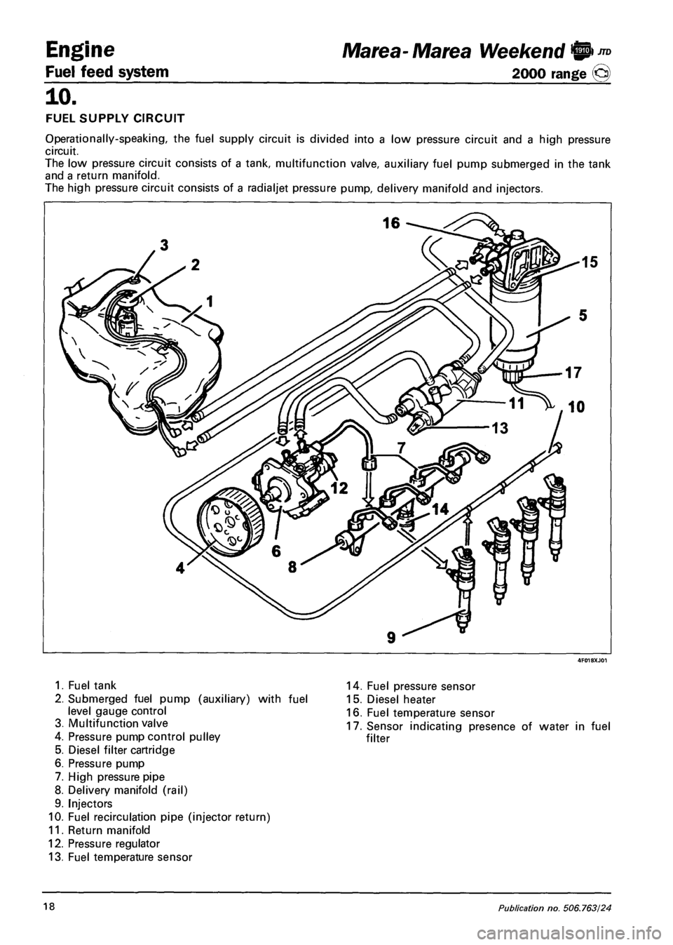
FUEL SUPPLY CIRCUIT
Operationally-speaking, the fuel supply circuit is divided into a low pressure circuit and a high pressure
circuit.
The low pressure circuit consists of a tank, multifunction valve, auxiliary fuel pump submerged in the tank
and a return manifold.
The high pressure circuit consists of a radialjet pressure pump, delivery manifold and injectors.
1. Fuel tank
2. Submerged fuel pump (auxiliary) with fuel
level gauge control
3. Multifunction valve
4. Pressure pump control pulley
5. Diesel filter cartridge
6. Pressure pump
7. High pressure pipe
8. Delivery manifold (rail)
9. Injectors
10. Fuel recirculation pipe (injector return)
11. Return manifold
12. Pressure regulator
13. Fuel temperature sensor
14. Fuel pressure sensor
15. Diesel heater
16. Fuel temperature sensor
17. Sensor indicating presence of water in fuel
filter
18 Publication no. 506.763/24
Page 105 of 330
Marea- Marea Weekend 9 ™
2000 range (Q)
4F019XJ01
1. Impeller
2. Volumes
3. Intake port
4. Outlet port
5. Rollers
6. Outer race
7. Pressure relief valve
4F019XJ02
Engine
Fuel feed system
10.
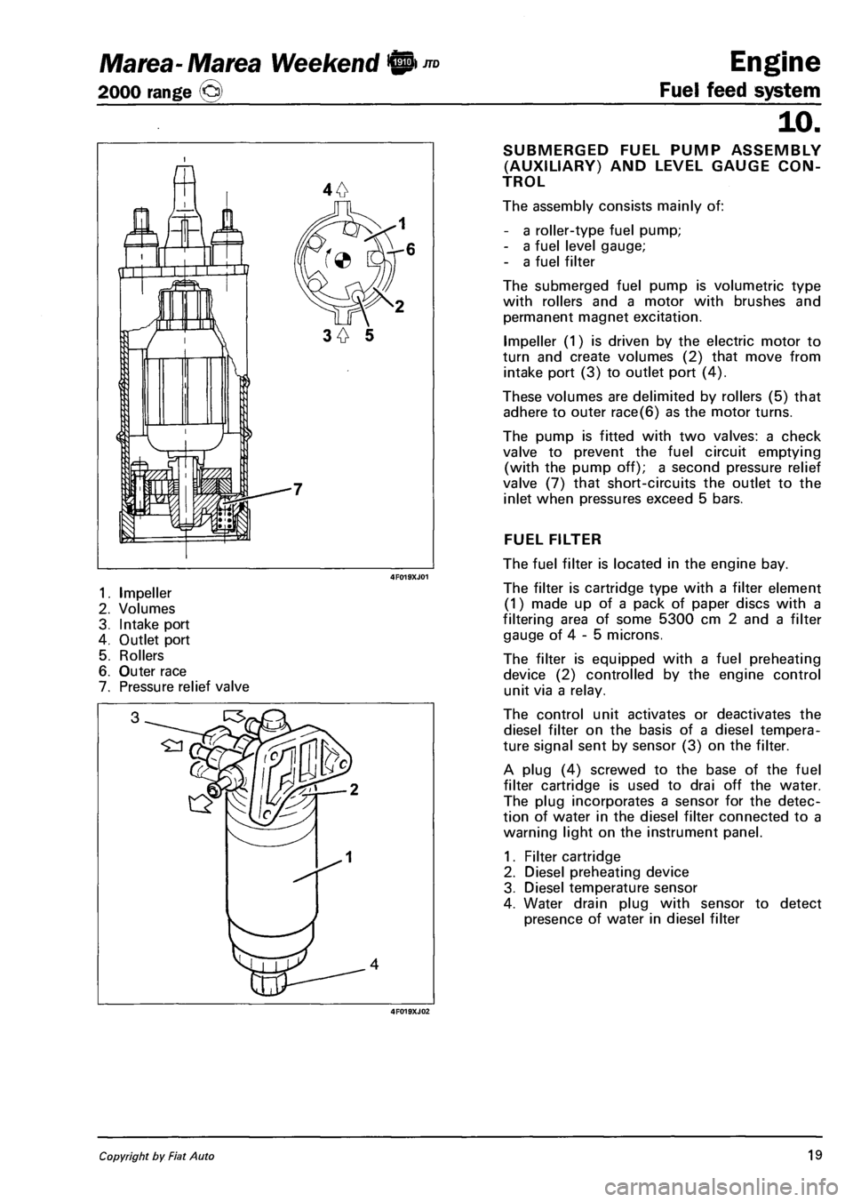
SUBMERGED FUEL PUMP ASSEMBLY
(AUXILIARY) AND LEVEL GAUGE CON
TROL
The assembly consists mainly of:
- a roller-type fuel pump;
- a fuel level gauge;
- a fuel filter
The submerged fuel pump is volumetric type
with rollers and a motor with brushes and
permanent magnet excitation.
Impeller (1) is driven by the electric motor to
turn and create volumes (2) that move from
intake port (3) to outlet port (4).
These volumes are delimited by rollers (5) that
adhere to outer race(6) as the motor turns.
The pump is fitted with two valves: a check
valve to prevent the fuel circuit emptying
(with the pump off); a second pressure relief
valve (7) that short-circuits the outlet to the
inlet when pressures exceed 5 bars.
FUEL FILTER
The fuel filter is located in the engine bay.
The filter is cartridge type with a filter element
(1) made up of a pack of paper discs with a
filtering area of some 5300 cm 2 and a filter
gauge of 4 - 5 microns.
The filter is equipped with a fuel preheating
device (2) controlled by the engine control
unit via a relay.
The control unit activates or deactivates the
diesel filter on the basis of a diesel tempera
ture signal sent by sensor (3) on the filter.
A plug (4) screwed to the base of the fuel
filter cartridge is used to drai off the water.
The plug incorporates a sensor for the detec
tion of water in the diesel filter connected to a
warning light on the instrument panel.
1. Filter cartridge
2. Diesel preheating device
3. Diesel temperature sensor
4. Water drain plug with sensor to detect
presence of water in diesel filter
Copyright by Fiat Auto 19
Page 144 of 330
Electrical equipment
Instrument panel
Marea-Marea Weekend
2000 range ©
55.
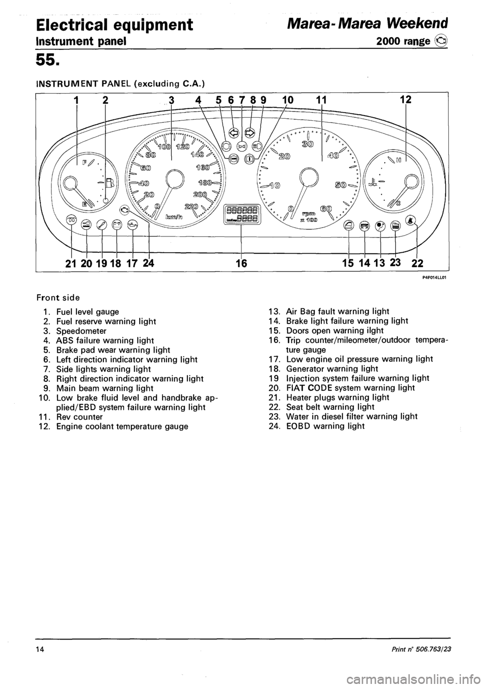
INSTRUMENT PANEL (excluding C.A.)
3 4 56789 10 11 12
21 20 1918 17 24 16 15 14 13 23 22
Front side
1. Fuel level gauge
2. Fuel reserve warning light
3. Speedometer
4. ABS failure warning light
5. Brake pad wear warning light
6. Left direction indicator warning light
7. Side lights warning light
8. Right direction indicator warning light
9. Main beam warning light
10. Low brake fluid level and handbrake ap-
plied/EBD system failure warning light
11. Rev counter
12. Engine coolant temperature gauge
13. Air Bag fault warning light
14. Brake light failure warning light
15. Doors open warning ilght
16. Trip counter/mileometer/outdoor tempera
ture gauge
17. Low engine oil pressure warning light
18. Generator warning light
19 Injection system failure warning light
20. FIAT CODE system warning light
21. Heater plugs warning light
22. Seat belt warning light
23. Water in diesel filter warning light
24. EOBD warning light
14 Print rf 506.763/23
Page 145 of 330
Marea- Marea Weekend
2000 range ©
Electrical equipment
Control module
55.
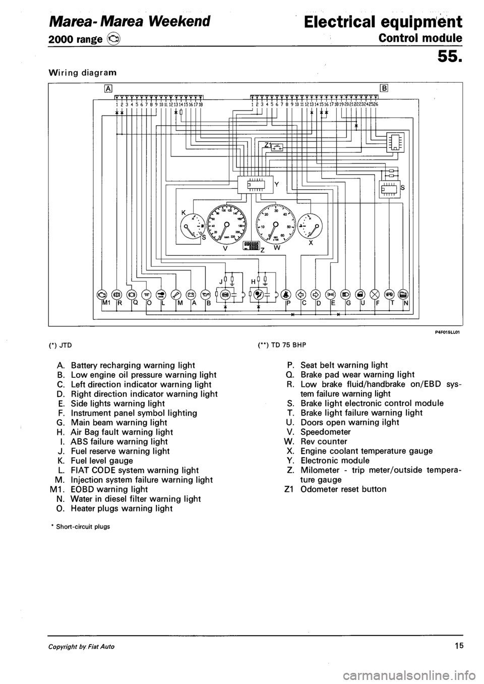
Wiring diagram
.mrmmmL 18 3 4 5 6 7 8 9 10 U 1213 1415161718 |TTTTrTrrrrTTTTT1.TTTTT1pmL 18 3 4 5 6 7 8 9 10 11 121314151617181920213223248586
n ti
O Mill
(*) JTD
A. Battery recharging warning light
B. Low engine oil pressure warning light
C. Left direction indicator warning light
D. Right direction indicator warning light
E. Side lights warning light
F. Instrument panel symbol lighting
G. Main beam warning light
H. Air Bag fault warning light
I. ABS failure warning light
J. Fuel reserve warning light
K. Fuel level gauge
L. FIAT CODE system warning light
M. Injection system failure warning light
M1. EOBD warning light
N. Water in diesel filter warning light
O. Heater plugs warning light
(**) TD 75 BHP
P. Seat belt warning light
Q. Brake pad wear warning light
R. Low brake fluid/handbrake on/EBD sys
tem failure warning light
S. Brake light electronic control module
T. Brake light failure warning light
U. Doors open warning ilght
V. Speedometer
W. Rev counter
X. Engine coolant temperature gauge
Y. Electronic module
Z. Milometer - trip meter/outside tempera
ture gauge
Z1 Odometer reset button
* Short-circuit plugs
Copyright by Fiat Auto 15
Page 147 of 330
Marea- Marea Weekend Electrical equipment
2000 range (Q) Control module
55.
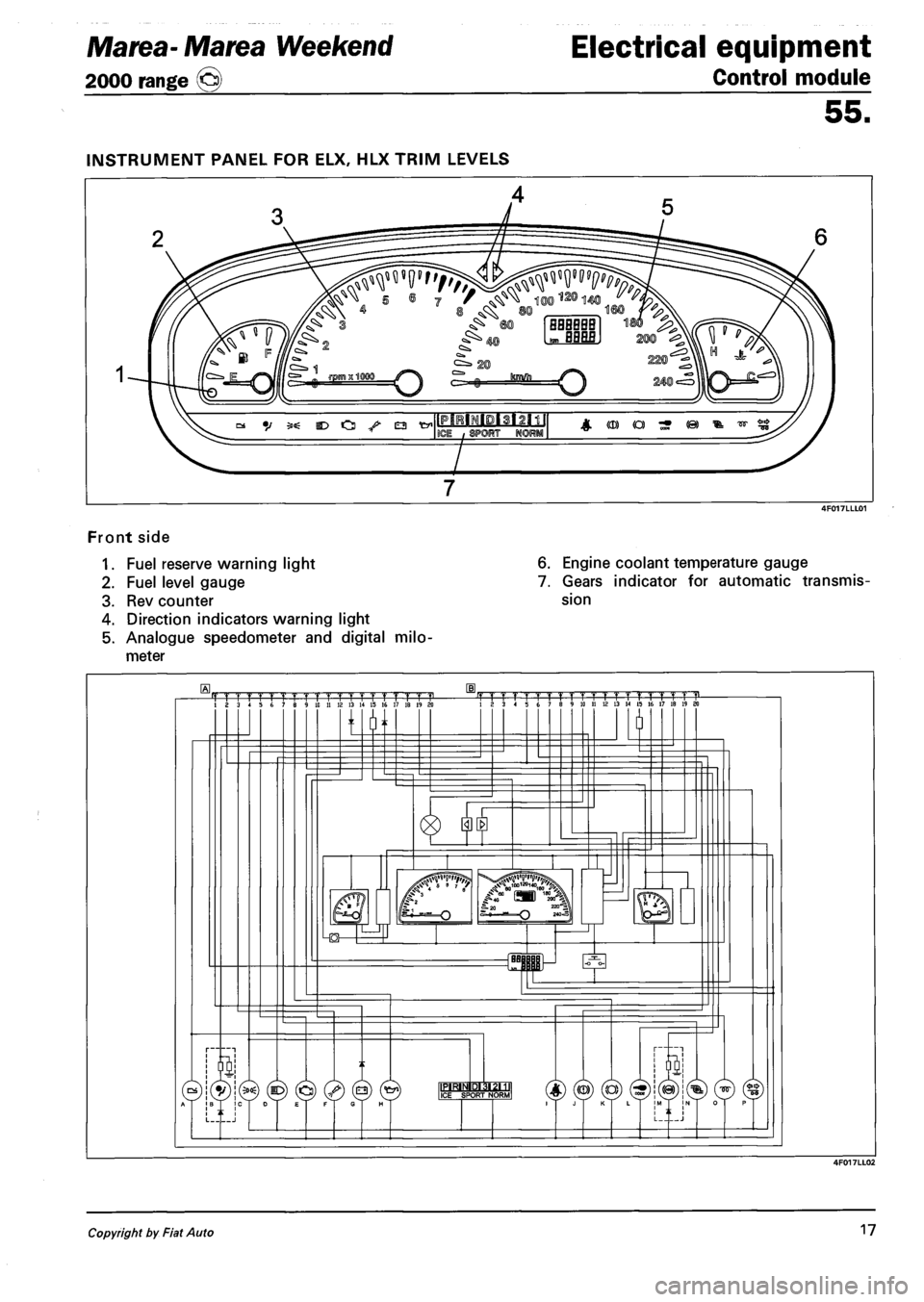
Front side
1. Fuel reserve warning light
2. Fuel level gauge
3. Rev counter
4. Direction indicators warning light
5. Analogue speedometer and digital milo
meter
6. Engine coolant temperature gauge
7. Gears indicator for automatic transmis
sion
Copyright by Fiat Auto 17
Page 148 of 330
Electrical equipment
Control module
Marea- Marea Weekend
2000 range ©
55.
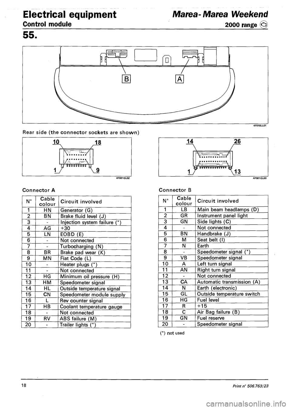
Rear side (the connector sockets are shown)
Connector A Connector B
N° Cable
colour Circuit involved
1 HN Generator (G)
2 BN Brake fluid level (J)
3 -Injection system failure (*)
4 AG +30
5 LN EOBD (E)
6 -Not connected
7 -Turbocharging (N)
8 BR Brake pad wear (K)
9 MN Fiat Code (L)
10 -Heater plugs (*)
11 -Not connected
12 HG Minimum oil pressure (H)
13 HM Speedometer signal
14 HL Outside temperature signal
15 CN Speedometer module supply
16 L Rev counter signal
17 HB Coolant temperature gauge
18 -Not connected
19 RV ABS failure (M)
20 -Trailer lights (*)
N° Cable
colour Circuit involved
1 LB Main beam headlamps (D)
2 GR Instrument panel light
3 GN Side lights (C)
4 -Not connected
5 BN Handbrake (J)
6 M Seat belt (I)
7 N Earth
8 -Speedometer signal (*)
9 VB Speedometer signal
10 A Left turn signal
11 AN Right turn signal
12 -Not connected
13 CA Automatic transmission (A)
14 N Earth (electronic)
15 GL Outside temperature switch
16 HG Fuel level
17 R + 15
18 C Air Bag failure (B)
19 GN Fuel reserve
20 -Speedometer signal
(*) not used
18 Print n° 506.763/23
Page 189 of 330
Marea- Marea Weekend
2000 range ©
Electrical equipment
Wiring diagrams
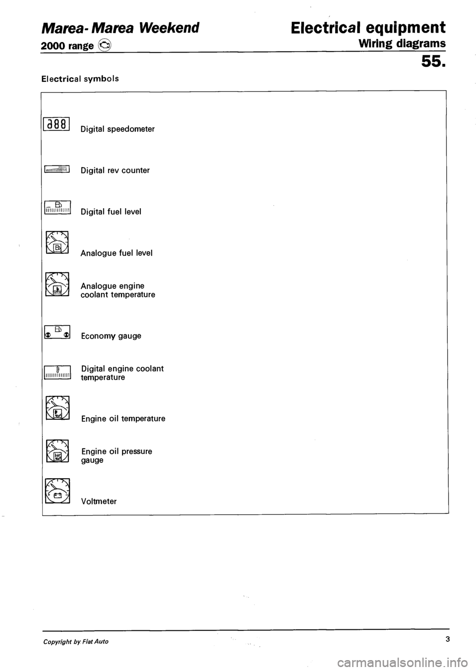
Electrical symbols
55.
388
_ a IIIIIIIIIIMI
'
Eb * ®
minium
Ev3
'
Digital rev counter
Digital fuel level
Analogue fuel level
Analogue engine
coolant temperature
Economy gauge
Digital engine coolant
temperature
Engine oil temperature
vfOSv EN9|NE °'l pressure M35^ gauge
iE2 Voltmeter
Copyright by Fiat Auto 3
Page 234 of 330
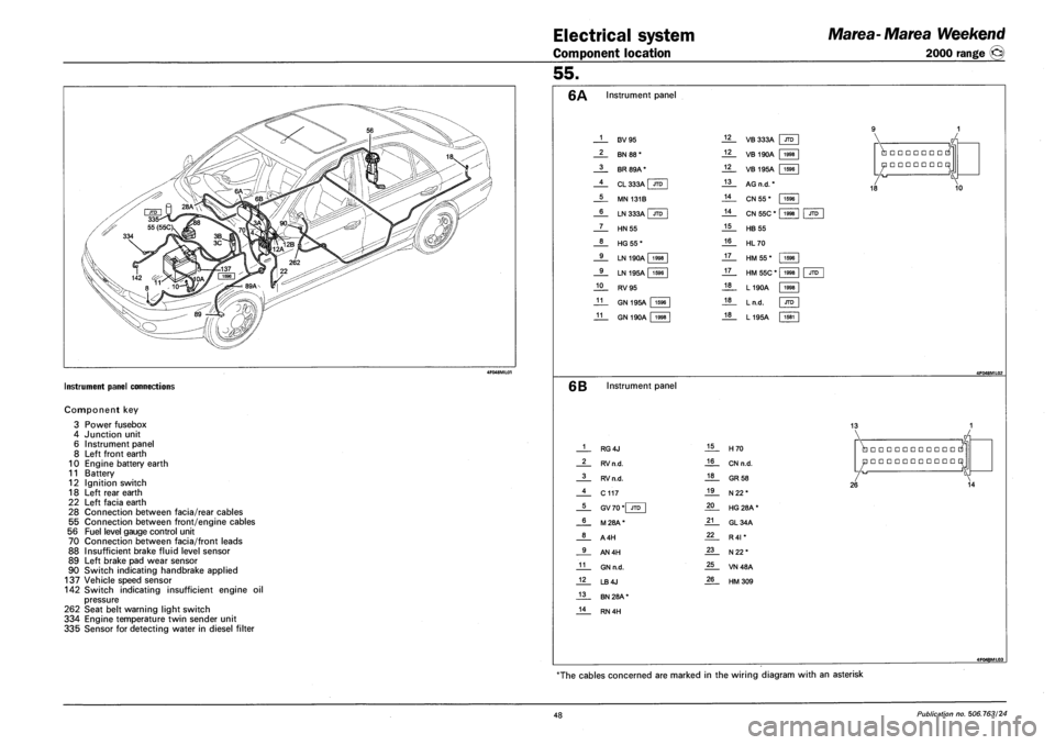
Electrical system
Component location
Marea-Marea Weekend
2000 range ©
INSTRUMENT PANEL CONNECTIONS
Component key
3
4
6
8
10
11
12
18
22
28
55
56
70
88
89
90
Power fusebox
Junction unit
Instrument panel
Left front earth
Engine battery earth
Battery
Ignition switch
Left rear earth
Left facia earth
Connection between facia/rear cables
Connection between front/engine cables
Fuel level gauge control unit
Connection between facia/front leads
Insufficient brake fluid level sensor
Left brake pad wear sensor
Switch indicating handbrake applied
137 Vehicle speed sensor
142 Switch indicating insufficient engine oil
pressure
262 Seat belt warning light switch
334 Engine temperature twin sender unit
335 Sensor for detecting water in diesel filter
55.
Instrument panel
1
2
3
4
5
6
7
8
9
9
10
11
11
F3V95
BN 88*
BR 89A*
CL 333A I JTD
MN 131B
LN 333A | JTD
HN55
HG55*
LN 190A 1998
LN 195A | 1596
RV95
GN 195A 1596
GN 190A 1998
12
12
12
13
14
14
15
16
17
17
18
18
18
VB 333A JTD
VB 190A 1998
1596
1998
VB 195A | 1596
AG n.d. *
CN 55 *
CN 55C *
HB 55
HL70
HM 55*
HM 55C * |
L190A
Ln.d.
L195A
•••••••
•••••••
18 10
JTD
1596
1998
1998
JTD
1581
6B Instrument panel
13
1
2
3
4
5
6
8
9
11
12
13
14
RG4J
RV n.d.
RV n.d.
C117
GV 70 *| JTD
M28A*
A4H
AN4H
GN n.d.
LB4J
BN 28A *
RN 4H
15
16
18
19
20
21
22
23
25
26
H70
CN n.d.
GR 58
N22*
HG 28A *
GL34A
R4I *
N22*
VN48A
HM309
•••••••••••
•••••••••••
26 14
4F048ML03
The cables concerned are marked in the wiring diagram with an asterisk
48 Publication no. 506.763/24
Page 236 of 330
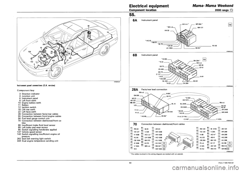
Electrical equipment
Component location
Marea-Marea Weekend
2000 range ®
Instrument panel connections (C.A. version)
Component key
3 Direction indicator
4 Junction unit
6 Instrument panel
8 Left front earth
10 Engine battery earth
11 Battery
12 Ignition switch
18 Left rear earth
22 Left facia earth
28 Connection between facia/rear cables
55 Connection between front/engine cables
56 Fuel level gauge control unit
70 Connection between dashborad/front ca
bles
88 Insufficient brake fluid level sensor
89 Left brake pad wear sensor
90 Switch signalling handbrake applied
137 Vehicle speed sensor
142 Switch signalling insufficient engine oil
pressure
262 Seat belt warning light switch
334 Dual engine temperature sending unit
55.
6A Instrument panel
AG n.d. * BR 89A *
MN 131
HG 55 *HM55
RV95
6B Instrument panel
GL34A
*N22
AN4H
28A Facia/rear lead connection
RN n.d
GN 309
NZ22
AR120
MB34A
V70
RN n.d.
V107A
70 Connection between dashborad/front cables
A1 B1 C1 — RN4C — M29 — AN4C A2 B2 C2 — VG127 — V328 — HR100B A3 B3 C3 — H100B — AG n.d. * — HN 100B A4 B4 C4 — HL6A — LN 100B — HG 100B A5 B5 C5 — CB 100A — BN 375 — HV 100B A6 B6 C7 | — S100B — B375 — GV335 JTD A7 B8 C8 • — V 100A — MN n.d. — RB 307 I TAXI A8 C8 — N 8 — GN 195A ^
A1 — RN120 A2 — VG120 A3 — H6B A4 — HL120 A5 — CB28A A6 — Rn.d. A7 — A34A A8 — N312
B1 — M 310C B2 — V28A B3 — AG 41* B4 — AB4I B5 — BN120 B6 — B117 B7 — AN 120 B8
C1 — AN 120 C2 — HR28B C3 — HN28B C4 — HG28B C5 — HV28B C7 — GV6B C8 JTD
C8 RB312 TAXI
RN315 — GN6BCS
4F060ML05
* The cables involved in the wiring diagram are marked with an asterisk.
50 Print n° 506.763/23