Knock FIAT MAREA 2000 1.G Workshop Manual
[x] Cancel search | Manufacturer: FIAT, Model Year: 2000, Model line: MAREA, Model: FIAT MAREA 2000 1.GPages: 330
Page 256 of 330

Electrical equipment
Component location
Marea-Marea Weekend
2000 range ©
55.
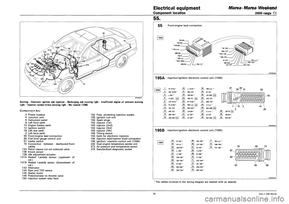
Starting - Electronic ignition and injection - Recharging and warning light
light - Injection system failure warning light - Rev counter (1596)
Insufficient engine oil pressure warning
Component key
3 Power fusebox
4 Junction unit:
6 Instrument panel
8 Left front earth
10 Engine battery earth
12 Ignition switch
18 Left rear earth
2 Left facia earth
55 Front/engine lead connection
56 Fuel level gauge control unit
57 Inertia switch
70 Connection between dashborad/front
cables
132 Petrol vapour cut out solenoid valve
136 Knock sensor
138 Idle adjustment actuator
141A Heated Lambda sensor (upstream of
cat.)
141 B Heated Lambda sensor (downstream of
cat.)
143 Alternator
144 Rpm and TDC sensor
145 Starter motor
146 Potentiometer on throttle valve
150 Injection system relay feed
152 Fuse protecting injection system
155 Ignition coil unit
156 Spark plugs
162 Injector (1st)
163 Injector (2nd)
164 Injector (3rd)
165 Injector (4th)
168 Timing sensor
193 Earth for electronic injection
194 Injection lead/injector braid connection
195 Ignition/ injection control unit (1596)
334 Dual engine temperature sender unit
373 Air pressure and temperature sensor
375 Standardized diagnostic socket
55 Front/engine lead connection
1596
CN6A.
HG6A.
* HN 6A
1 CN n.d.
MB6A.
NZ8_
* ZB n.d
*RG195A_
HM6A
CN n.d. HN 143 *
HG 142
1 95A Injection/ignition electronic control unit (1596)
1596 1 N 141A* 20 L 141A* 29 RN n.d. *
2 NZ141B* 21 BN 127 35 B 127
4 L6A* 23 GN 6A* 36 LR252 [c*
5 V252 0 23 GN70 0 40 AG 127
9 LN 141A* 24 B141B* 41 MG 127
12 R 141B* 25 BR n.d. 0 44 Vn.d.*
13 GV131 25 BR 375 * 46 BG 268 [a
14 AB 127 26 LN6A* 47 C n.d. *
15 SB 150* 27 N 193* 48 S 127
16 GN 252 [cal 28 N 193* 49 NZ252
27 282,9 41 52
O I I I I I I -r-r-r'n , , r'l -r-
rrrri '/ 1 1 1 1 1 1 1 1 1 1 1 \1 L/-HJ 'A i I I i i ,I
40
1 95B Injection/ignition electronic control unit (1596)
1596 53 R144* 65 VB 138* JL. NZn.d. *
54 N n.d. * 66 LR 155 * _ZL HM194*
55 ZB 278 * 67 B 144* _7JL HV194*
56 L136* 68 V278*
57 C138* 69 B 168*
58 HN 138* 70 Z136*
59 GN 155 * 71 HG 194 *
60 S 146* 72 HL194*
62 SN 339 * 75 RN 278 *
64 GR138* 76 BR 146 *
74
67-Jf Mill i i r r-l I I I
60-
IE
L -j |l
53 59
The cables involved in the wiring diagram are marked with an asterisk.
70 Print n° 506.763/23
Page 258 of 330

Electrical equipment
Component location
Marea-Marea Weekend
2000 range ®
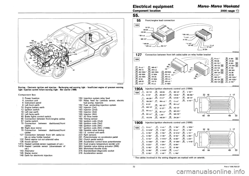
Starting - Electronic ignition and injection - Recharging and warning light
light- Injection system failure warning ilight - Rev counter (1998)
Insufficient engine oil pressure warning
Component key
3 Power fusebox
4 Junction unit
6 Instrument panel
8 Left front earth
10 Engine battery earth
12 Ignition switch
18 Left rear earth
22 Left facia earth
40 Brake lights control switch
55 Connection between front/engine cables
57 Inertia switch
70 Connection between dashborad/front
cables
68 Right door mirror
70 Connection between dashborad/front
cables
127 Connection between front left cable/ca
ble on relay holder bracket
132 Petrol vapour cut out solenoid valve
136 Knock sensor
141A Heated Lambda sensor (upstream of cat.)
141 B Heated Lambda sensor (downstream of
cat.)
143 Alternator
145 Starter motor
148 Earth for electronic injection
150 Injection system relay feed
151 Relay feed for Lambda sensor, electric
fuel pump, injectors
152 Fuse protecting injection system
162 Injector (1st)
163 Injector (2nd)
164 Injector (3rd)
165 Injector (4th)
167 Air flow meter
168 Timing sensor
184 Ignition coils (2nd)
185 Ignition coils (3rd)
186 Ignition coils (4th)
187 Ignition coils (5th) (1998)
189 Variable valve timing
193 I.E. control unit earth
223 Rpm sensors
291 Potentiometer on accelerator pedal
292 Clutch pedal switch
296 Accelerator control lever potentiometer
334 Dual engine temperature sender unit
363 Variable valve timing actuator (998)
364 Motorized throttle body
375 Standardized diagnostic socket
376 Acceleration sensor
55.
55 Front/engine lead connection
1998
* BV n.d
MN 127
' HN 6A
* AR n.d
1 27 Connection between front left cable/cable on relay holder bracket
1998
A1 R n.d.'
HL RN 13
HL BG 190A
A4 AB 190A
HL AG 190A
A6 M3A
HL MN55
HL C n.d. *
J*L MB 4C *
J*L AN n.d.
_§§_ MG 190A
_§£. S 190A
VN3A
66 B190A
_§7_ VG70
R n.d.
C2 BN190A
_2L HL n.d.
C4_ SG n.d.
C5 HRn.fi.'
C6 AR n.d. *
_5L G 190A
A1 R n.d. * B4 S365
HL RN98 B5 VN 98 A3 BV 151 * B6 B365 A4 AB 123 J7_ VG365 J*I
HL AG 122 B8 R 150 A6 M 124 C2 BN365 A7 MN 124 C3 HL98 A8 Cn.d.* C4 SG 98 B1 MB 151 * C5 HR152A* B2 AN 124 C6 AR 152B *
B3 MG 124 C7 G 150*
1 90A Injection/ignition electronic control unit (1998)
1998 3 GV131 22 GN6A 41 BN 127 57 V 167*
6 S 127 24 ZB 291 * 44 VB6A* 59 SB 292 *
7 AN 291 * 25 A n.d* 46 LN6A* 62 AB 127
"U 8 GN 291 * 27 RN n.d. * 47 Cn.d* 63 H 167* "U
9 B 127 30 BG 127 * 48 BV n.d *
13 MG 127 31 G 127* 50 AG 127
15 RV n.d. * 32 BV n.d * 53 BR 375 *
16 BV n.d * 35 L6A* 54 MN 167 *
21 VG376 40 HB 291 * 56 ZN 291 *
32 16
49 33
1 90B Injection/ignition electronic control unit (1998)
1998 1 G n.d. * 17 V n.d. * 32 V184* 52 L165A*
2 G 141B* 19 V162* 33 B n.d. * 54 L 136*
3 G 165* 20 V164* 34 B 141A* 55 L 141 *
4 G 189* 22 V136* 35 B 163* 58 L364*
5 G 132* 23 V141A* 36 B363* 59 L223*
6 G 136A* 24 V364* 38 B 136A*. 60 L141B*
10 G223* 25 V334* 40 B364*
14 G 185* 26 V n.d. * 42 B 168*
15 G 186* 28 V 141B* 49 L n.d. *
16 G 183* 31 V187* 51 L 168*
49 33
* The cables involved in the wiring diagram are marked with an asterisk.
72 Print n° 506.763/23