OBD FIAT MAREA 2000 1.G Workshop Manual
[x] Cancel search | Manufacturer: FIAT, Model Year: 2000, Model line: MAREA, Model: FIAT MAREA 2000 1.GPages: 330
Page 69 of 330
Marea- Marea Weekend • ^ Engine
2000 range (Q) Fuel feed system
10.
ENGINE MANAGEMENT SYSTEM
The Marea-Marea Weekend 1596 16v has a 4 cylinder in line engine, with 16 valves, 1596 cc, twin over
head camshaft and a Marelli IAW 4EF integrated electronic injection/ignition system.
The fuel system differs from the one described for the 1581 16v "99 range" version through the addition
of several variants to make it compatible with the EEC Stage 3 EOBD regulations.
The main modifications to the system can be summarized as follows:
- Engine management control unit with IAW 4EF
- Catalytic converter near the exhaust manifold to take maximum advantage of the heat of the gases.
- Two Lambda senors, one upstream (front) and one downstream (rear) which check the quality of the
exhaust gases and the operation of the catalyzer.
- Adoption of a timing sensor on the inlet side timing pulley.
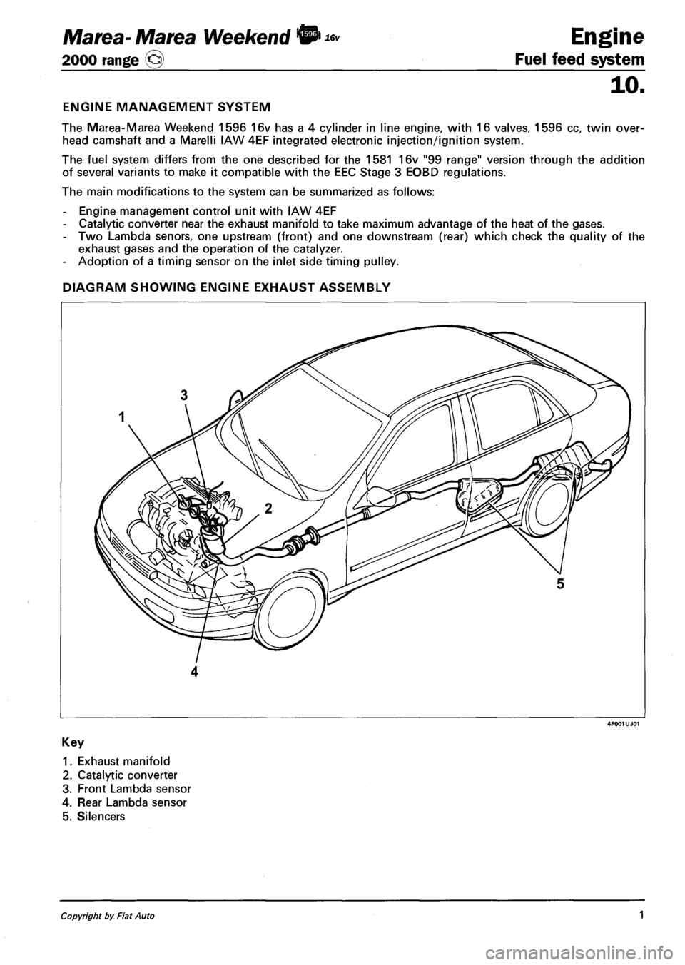
DIAGRAM SHOWING ENGINE EXHAUST ASSEMBLY
1. Exhaust manifold
2. Catalytic converter
3. Front Lambda sensor
4. Rear Lambda sensor
5. Silencers
Copyright by Fiat Auto 1
Page 78 of 330
Marea- Marea Weekend & Engine
2000 range (§) Fuel feed system
ENGINE MANAGEMENT SYSTEM
Foreword
The Marea-Marea Weekend 1998 20v is equipped with a 5 cylinder in line engine with 20 valves, 1998
cc, twin overhead camshaft and a Bosch ME3.1 integrated electronic injection/ignition system.
The fuel system differs from the one described for the 1998 20v "99 range" version through the addition
of several variants to make it compatible with the EEC Stage 3 EOBD regulations.
The main modifications to the system can be summarized as follows:
- Catalytic converter near the exhaust manifold to take maximum advantage of the heat of the gases.
- Two Lambda sensors, one upstream (front) and one downstream (rear) which check the quality of the
exhaust gases and the operation of the catalyzer.
- Adoption of an accelerometre sensor on the right shock absorber turret, used to distinguish between
engine torque variations doe to the uneveness of the road surface and those due to failed ignition in
the combustion chamber (misfire).
- Adoption of a timing sensor on the inlet side timing pulley.
- Multi-purpose valve on the tank to prevent leaks.
- Adoption of raipd attachment connectors for the anti-evaporation system pipes.
- Cap on the fuel filler with an attachment cable.
For further information on the fuel system, refer to publication 507137.
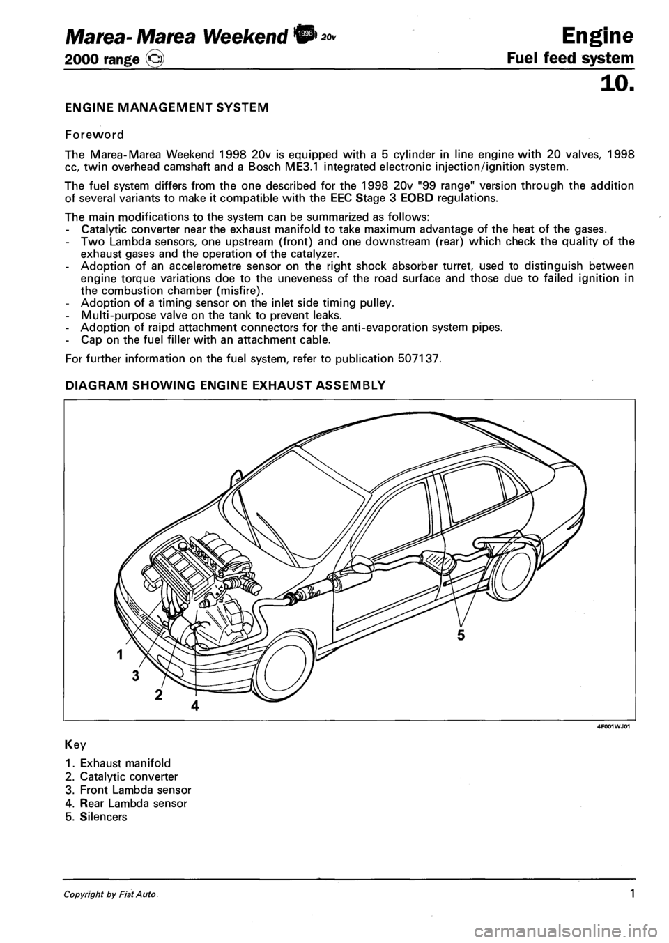
DIAGRAM SHOWING ENGINE EXHAUST ASSEMBLY
4F001WJ01
Key
1. Exhaust manifold
2. Catalytic converter
3. Front Lambda sensor
4. Rear Lambda sensor
5. Silencers
Copyright by Fiat Auto 1
Page 91 of 330
![FIAT MAREA 2000 1.G Workshop Manual Marea-Marea Weekend 9]
2000 range (j§)
I) JTD
Fuel feed system
Engine
10.
Exhaust fumes control
Through this function the injection control unit limits any exhaust fumes that could be produce FIAT MAREA 2000 1.G Workshop Manual Marea-Marea Weekend 9]
2000 range (j§)
I) JTD
Fuel feed system
Engine
10.
Exhaust fumes control
Through this function the injection control unit limits any exhaust fumes that could be produce](/img/10/4653/w960_4653-90.png)
Marea-Marea Weekend 9]
2000 range (j§)
I) JTD
Fuel feed system
Engine
10.
Exhaust fumes control
Through this function the injection control unit limits any exhaust fumes that could be produced during
transition speeds.
To satisy these requirements the control unit processes the signals supplied by the accelerator pedal po
tentiometer, the rpm sensor and the air flow meter and controls the fuel pressure regulator and the injec
tors to meter the correct amount of fuel to inject.
Exhaust gas recirculation control
On the basis of the signals supplied by the rpm sensor, intake air quantity sensor, engine coolant tempe
rature sensor and accelerator pedal position sensor, the control unit calculates the operating times for the
EGR valve so that the exhaust gases are partly recirculated in certain engine operating conditions in line
with Euro 3 pollution control standards.
Air conditioning system engagement control
The injection control unit manages the operation of the air conditioning system compressor electro
magnet coupling following a logic aimed at preventing operating conditions that would adversely affect
engine performance.
- When the compressor is switched on the injection control unit increases the quantity of fuel during
idling to allow the engine to adjust to the increased power requirements and momentarily interrupts the
supply to the compressor in high engine power requirement conditions (strong acceleration).
Engine immobilizer function control
The system is equipped with an engine immobilizer function. This function is achieved through the pre
sence of a specific control unit (Fiat CODE), capable of conversing with the injection control unit and an
electronic key with a special transmitter for sending a recognition code.
Each time the key is turned to the OFF position, the Fiat CODE system completely deactivates the injecti
on control unit.
When the key is turned to the ON position the following operations take place, in order:
1. the injection control unit (whose memory contains a secret code) sends the Fiat CODE control unit a
request to send the secret code to deactivate the immobilizer functions;
2. the Fiat CODE control unit responds by only sending the secret code after, in turn, having received the
recognition code transmitted by the ignition key;
3. the recognition of the secret code allows the deactivation of the injection control unit immobilizer func
tion and its normal operation.
Autodiagnosis
The complete electronic fault diagnosis of the injection system is carried out by connecting the special
equipment (EXAMINER or EXAMINER PLUS) to the standardized diagnostic socket (EOBD).
The system is also equipped with a self-diagnostic function which recognizes, memorizes and signals any
faults.
If a fault is detected in the sensors or actuators, the recovery strategy is immediately activated in order to
ensure that the engine functions at an acceptable level. The vehicle can be driven to a service centre for
the appropriate repairs to be carried out.
Copyright by Fiat Auto 5
Page 143 of 330
Marea- Marea Weekend
2000 range ©
Electrical equipment
Control module
55.
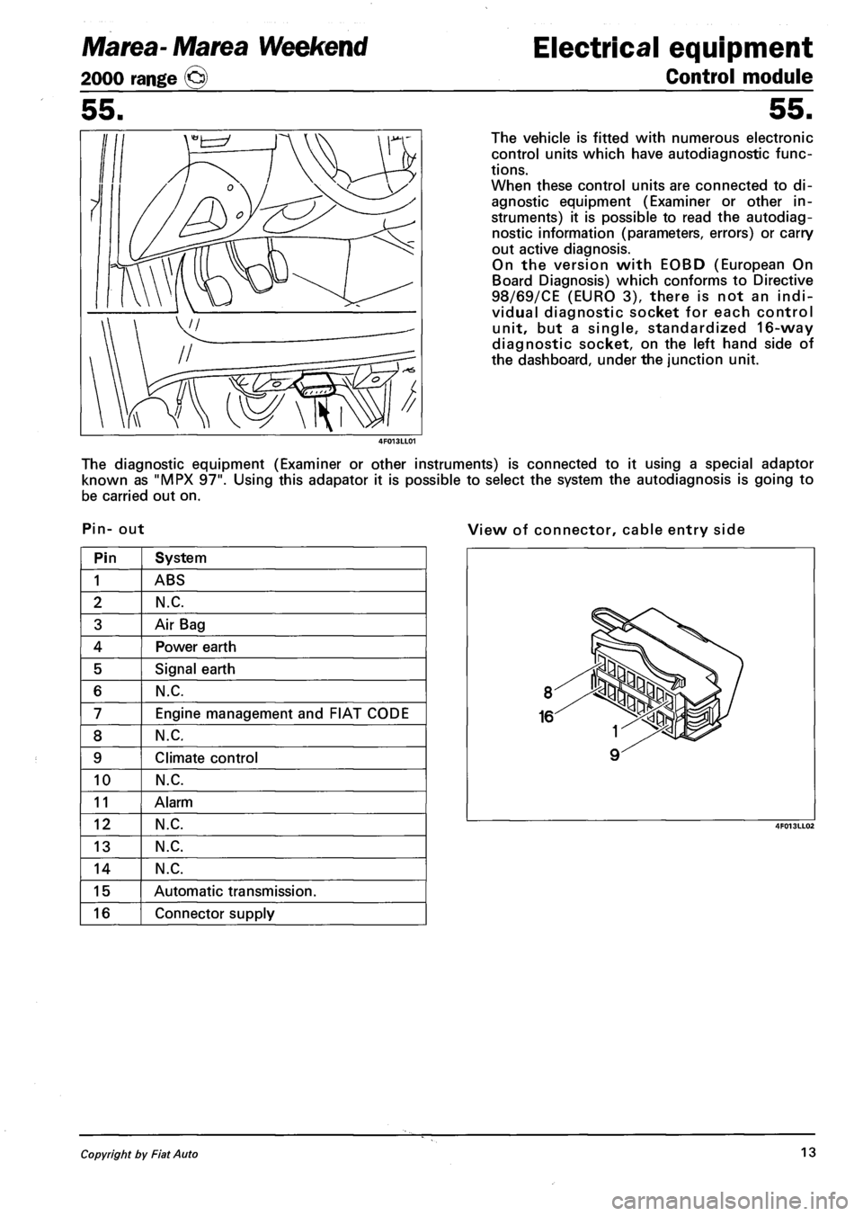
The vehicle is fitted with numerous electronic
control units which have autodiagnostic func
tions.
When these control units are connected to di
agnostic equipment (Examiner or other in
struments) it is possible to read the autodiag
nostic information (parameters, errors) or carry
out active diagnosis.
On the version with EOBD (European On
Board Diagnosis) which conforms to Directive
98/69/CE (EURO 3), there is not an indi
vidual diagnostic socket for each control
unit, but a single.- standardized 16-way
diagnostic socket, on the left hand side of
the dashboard, under the junction unit.
The diagnostic equipment (Examiner or other instruments) is connected to it using a special adaptor
known as "MPX 97". Using this adapator it is possible to select the system the autodiagnosis is going to
be carried out on.
Pin- out View of connector, cable entry side
Pin System
1 ABS
2 N.C.
3 Air Bag
4 Power earth
5 Signal earth
6 N.C.
7 Engine management and FIAT CODE
8 N.C.
9 Climate control
10 N.C.
11 Alarm
12 N.C.
13 N.C.
14 N.C.
15 Automatic transmission.
16 Connector supply
Copyright by Fiat Auto 13
Page 144 of 330
Electrical equipment
Instrument panel
Marea-Marea Weekend
2000 range ©
55.
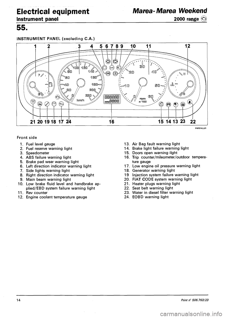
INSTRUMENT PANEL (excluding C.A.)
3 4 56789 10 11 12
21 20 1918 17 24 16 15 14 13 23 22
Front side
1. Fuel level gauge
2. Fuel reserve warning light
3. Speedometer
4. ABS failure warning light
5. Brake pad wear warning light
6. Left direction indicator warning light
7. Side lights warning light
8. Right direction indicator warning light
9. Main beam warning light
10. Low brake fluid level and handbrake ap-
plied/EBD system failure warning light
11. Rev counter
12. Engine coolant temperature gauge
13. Air Bag fault warning light
14. Brake light failure warning light
15. Doors open warning ilght
16. Trip counter/mileometer/outdoor tempera
ture gauge
17. Low engine oil pressure warning light
18. Generator warning light
19 Injection system failure warning light
20. FIAT CODE system warning light
21. Heater plugs warning light
22. Seat belt warning light
23. Water in diesel filter warning light
24. EOBD warning light
14 Print rf 506.763/23
Page 145 of 330
Marea- Marea Weekend
2000 range ©
Electrical equipment
Control module
55.
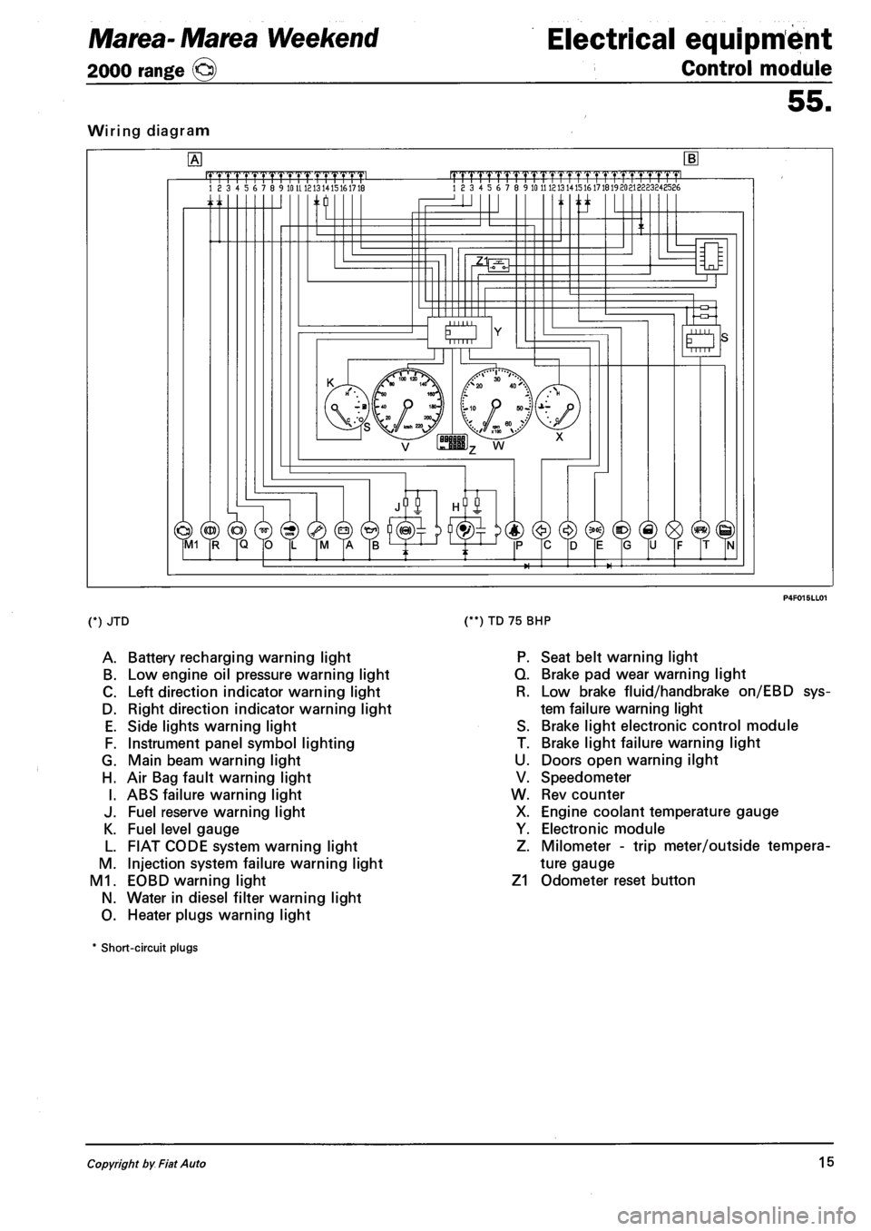
Wiring diagram
.mrmmmL 18 3 4 5 6 7 8 9 10 U 1213 1415161718 |TTTTrTrrrrTTTTT1.TTTTT1pmL 18 3 4 5 6 7 8 9 10 11 121314151617181920213223248586
n ti
O Mill
(*) JTD
A. Battery recharging warning light
B. Low engine oil pressure warning light
C. Left direction indicator warning light
D. Right direction indicator warning light
E. Side lights warning light
F. Instrument panel symbol lighting
G. Main beam warning light
H. Air Bag fault warning light
I. ABS failure warning light
J. Fuel reserve warning light
K. Fuel level gauge
L. FIAT CODE system warning light
M. Injection system failure warning light
M1. EOBD warning light
N. Water in diesel filter warning light
O. Heater plugs warning light
(**) TD 75 BHP
P. Seat belt warning light
Q. Brake pad wear warning light
R. Low brake fluid/handbrake on/EBD sys
tem failure warning light
S. Brake light electronic control module
T. Brake light failure warning light
U. Doors open warning ilght
V. Speedometer
W. Rev counter
X. Engine coolant temperature gauge
Y. Electronic module
Z. Milometer - trip meter/outside tempera
ture gauge
Z1 Odometer reset button
* Short-circuit plugs
Copyright by Fiat Auto 15
Page 146 of 330
Electrical equipment
Instrument panel
Marea- Marea Weekend
2000 range ©
55.
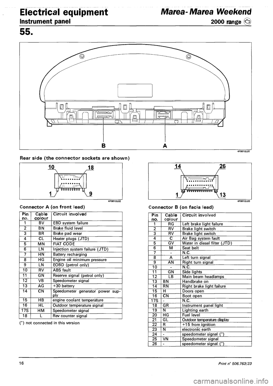
Rear side (the connector sockets are shown)
Connector A (on front lead) Connector B (on facia lead)
Pin no. Cable colour Circuit involved
1 BV EBD system failure
2 BN Brake fluid level
3 BR Brake pad wear
4 CL Heater plugs (JTD)
5 MN FIAT CODE
6 LN Injection system failure (JTD)
7 HN Battery recharging
8 HG Engine oil minimum pressure
9 LN EOBD (petrol only)
10 RV ABS fault
11 GN Reserve signal (petrol only)
12 VB Speedometer signal
13 AG +30 battery
14 CN Speedometer generator power supply
15 HB engine coolant temperature
16 HL Outdoor temperature signal
17S HM Speedometer signal
18 L Rev counter signal
(*) not connected in this version
Pin no. Cable colour Circuit involved
1 RG Left brake light failure
2 RV Brake light switch
3 RV Brake light switch
4 C Air Bag system fault
5 GV Water in diesel filter (JTD)
6 M Seat belt
7 -N.C.
8 A Left turn signal
9 AN Right turn signal
10 -N.C.
11 GN Side lights
12 LB Main beam headlamps
13 BN Handbrake on
14 RN Right brake light failure
15 H Doors open
16 CN Boot open
17S -N.C.
18 GR Instrument panel light
19 N Lighting earth
20 HG Fuel level
21 GL Outdoor temperature display
22 R +15 from ignition
23 N electronic earth
24 -speedometer signal (*)
25 VN Speedometer signal
26 -speedometer signal (*)
16 Print n° 506.763/23
Page 148 of 330
Electrical equipment
Control module
Marea- Marea Weekend
2000 range ©
55.
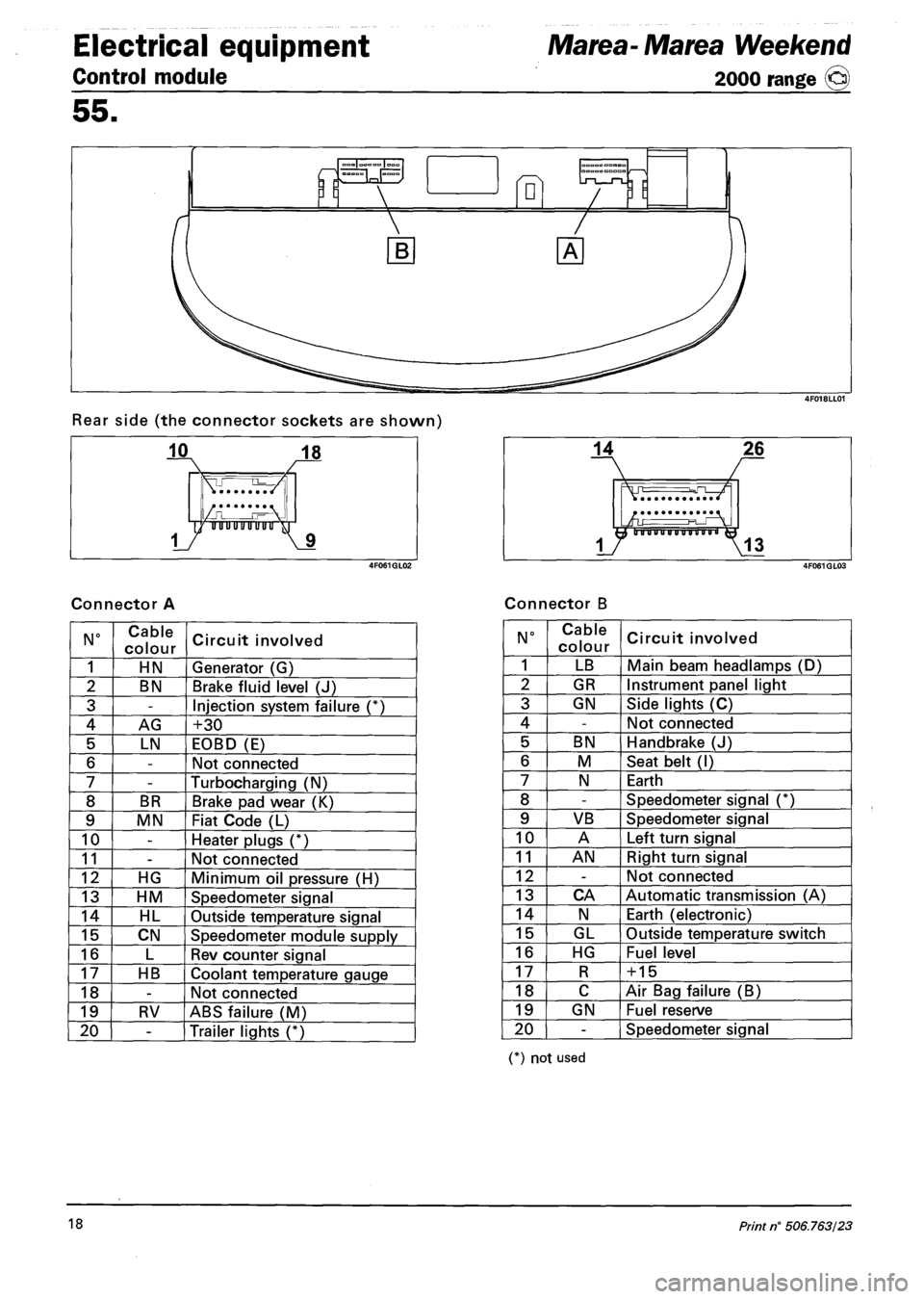
Rear side (the connector sockets are shown)
Connector A Connector B
N° Cable
colour Circuit involved
1 HN Generator (G)
2 BN Brake fluid level (J)
3 -Injection system failure (*)
4 AG +30
5 LN EOBD (E)
6 -Not connected
7 -Turbocharging (N)
8 BR Brake pad wear (K)
9 MN Fiat Code (L)
10 -Heater plugs (*)
11 -Not connected
12 HG Minimum oil pressure (H)
13 HM Speedometer signal
14 HL Outside temperature signal
15 CN Speedometer module supply
16 L Rev counter signal
17 HB Coolant temperature gauge
18 -Not connected
19 RV ABS failure (M)
20 -Trailer lights (*)
N° Cable
colour Circuit involved
1 LB Main beam headlamps (D)
2 GR Instrument panel light
3 GN Side lights (C)
4 -Not connected
5 BN Handbrake (J)
6 M Seat belt (I)
7 N Earth
8 -Speedometer signal (*)
9 VB Speedometer signal
10 A Left turn signal
11 AN Right turn signal
12 -Not connected
13 CA Automatic transmission (A)
14 N Earth (electronic)
15 GL Outside temperature switch
16 HG Fuel level
17 R + 15
18 C Air Bag failure (B)
19 GN Fuel reserve
20 -Speedometer signal
(*) not used
18 Print n° 506.763/23