starter FIAT MAREA 2000 1.G Workshop Manual
[x] Cancel search | Manufacturer: FIAT, Model Year: 2000, Model line: MAREA, Model: FIAT MAREA 2000 1.GPages: 330
Page 53 of 330
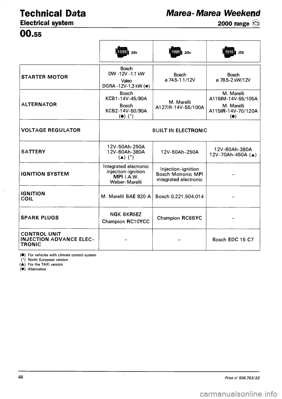
Technical Data Marea- Marea Weekend
Electrical system 2000 range (§)
00.55
i^p} 16v J^M) 20v
STARTER MOTOR
Bosch
DW -12V -1.1 kW
Valeo
DGRA-12V-1,3kW(B)
Bosch
0 74.5-1.1/12V
Bosch
O 78.5-2 kW/12V
ALTERNATOR
Bosch
KCB1-14V-45/80A
Bosch
KCB2-14V-50/90A
(•) n
M. Marelli
A127IR-14V-55/100A
M. Marelli
A115IM-14V-55/105A
M. Marelli
A115IR-14V-70/120A
(•)
VOLTAGE REGULATOR BUILT IN ELECTRONIC
BATTERY
12V-50Ah-250A
12V-60Ah-380A
(A) n
12V-50Ah-250A 12V-60Ah-380A
12V-70Ah-450A (A)
IGNITION SYSTEM
Integrated electronic
injection-ignition
MPI I.A.W.
Weber-Marelli
Injection-ignition
Bosch Motronic MPI
integrated electronic
-
IGNITION
COIL M. Marelli BAE 920 A Bosch 0.221.504.014 -
SPARK PLUGS NGK BKR5EZ
Champion RC10YCC Champion RC8BYC -
CONTROL UNIT
INJECTION ADVANCE ELEC
TRONIC
--Bosch EDC 15 C7
(•) For vehicles with climate control system (*) North European version (A) For the TAXI version
(•) Alternative
46 Print n° 506.763/23
Page 54 of 330
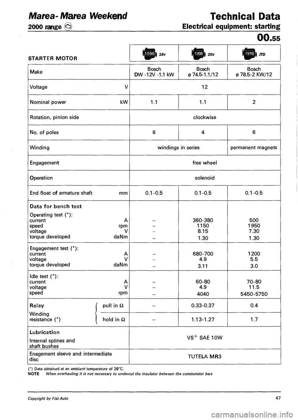
Marea- Marea Weekend Technical Data
2000 range (§) Electrical equipment: starting
00.55
STARTER MOTOR l^p| 20v I^P) JTD
Make Bosch
DW -12V -1,1 kW
Bosch
0 74.5-1.1/12
Bosch
0 78.5-2 KW/12
Voltage V 12
Nominal power kW 1.1 1.1 2
Rotation, pinion side clockwise
No. of poles 6 4 6
Winding windings in series permanent magnets
Engagement free wheel
Operation solenoid
End float of armature shaft mm 0.1-0.5 0.1-0.5 0.1-0.5
Data for bench test
Operating test (*):
current A
speed rpm
voltage V
torque developed daNm
-
360-380
1150
8.15
1.30
500
1950
7.30
1.30
Engagement test (*):
current A
voltage V
torque developed daNm
-680-700
4.9
3.11
1200
5.5
3.0
Idle test (*):
current A
voltage V
speed rpm
-
60-80
4.9
4040
70-80
11.5
5450-5750
Relay [ pull in Q -0.33-0.37 0.4
Winding
resistance (*) 1 hold in Q -1.13-1.27 1.7
Lubrication
Internal splines and
shaft bushes
VS+ SAE 10W
Enagement sleeve and intermediate
disc TUTELA MR3
(*) Data obtained at an ambient temperature of 20°C.
NOTE When overhauling it is not necessary to undercut the insulator between the commutator bars
Copyright by Fiat Auto 47
Page 131 of 330
Marea- Marea Weekend
2000 range ©
Electrical equipment
Protection and security devices
55.
PROTECTION AND SAFETY DEVICES
All the vehicle supply lines were designed taking into account the most up-to-date directives in terms of
safety and protection, especially to prevent fires.
There are 2 types of protection:
- active protection, aims to reduce the causes of faults "at source"
- passive protection, aims to limit the effects of a fault as much as possible
The first category includes a carefully designed wiring layout with wires positioned and carefully anchored
on tracks that are repaired and protected if necessary.
The cables connected to the alternator and the motor were modified for this reason by adding protective
caps etc. A strengthened sheath was also introduced for some of the more exposed sections of wiring.
The passive protection includes all interventions to reduce faults due to high current (overload, short cir
cuit).
All system fuses were rated based on the nominal absorbtion of the loads activated at the same time, to
ensure intervention in cases of a clear short circuit.
The introduction of a box containing 4 maxifuses with other fuses connected on the outside means all
the supplies can be protected except for the cable that connects the battery to the starter motor and the
cable that connects the starter motor to the recharging alternator. These cables are therefore protected by a
strengthened supplementary sheath.
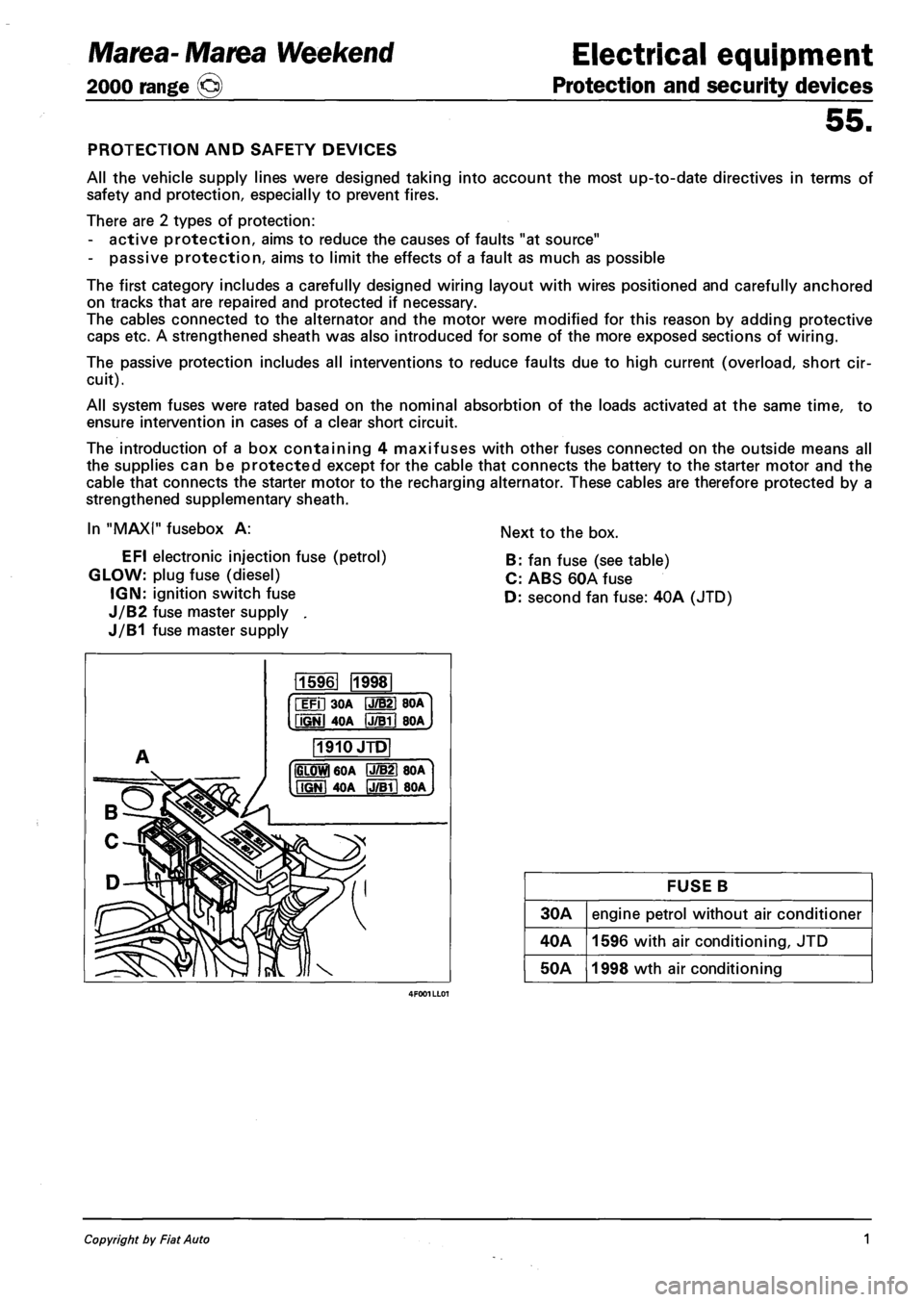
In "MAXI" fusebox A:
EFI electronic injection fuse (petrol)
GLOW: plug fuse (diesel)
IGN: ignition switch fuse
J/B2 fuse master supply .
J/B1 fuse master supply
Next to the box.
B: fan fuse (see table)
C: ABS 60A fuse
D: second fan fuse: 40A (JTD)
115961 1998
iFil 30A IJ/B21 BOA
fiGNl 4OA IJTBTI BOA
1910JTD
IGLOWl 60A P7B21 80A
MGNI 40A IJ/Bll 80A
FUSE B
30A engine petrol without air conditioner
40A 1596 with air conditioning, JTD
50A 1998 wth air conditioning
Copyright by Fiat Auto 1
Page 139 of 330
Marea-Marea Weekend Electrical equipment
2000 range (§) Location of components on the car
55.
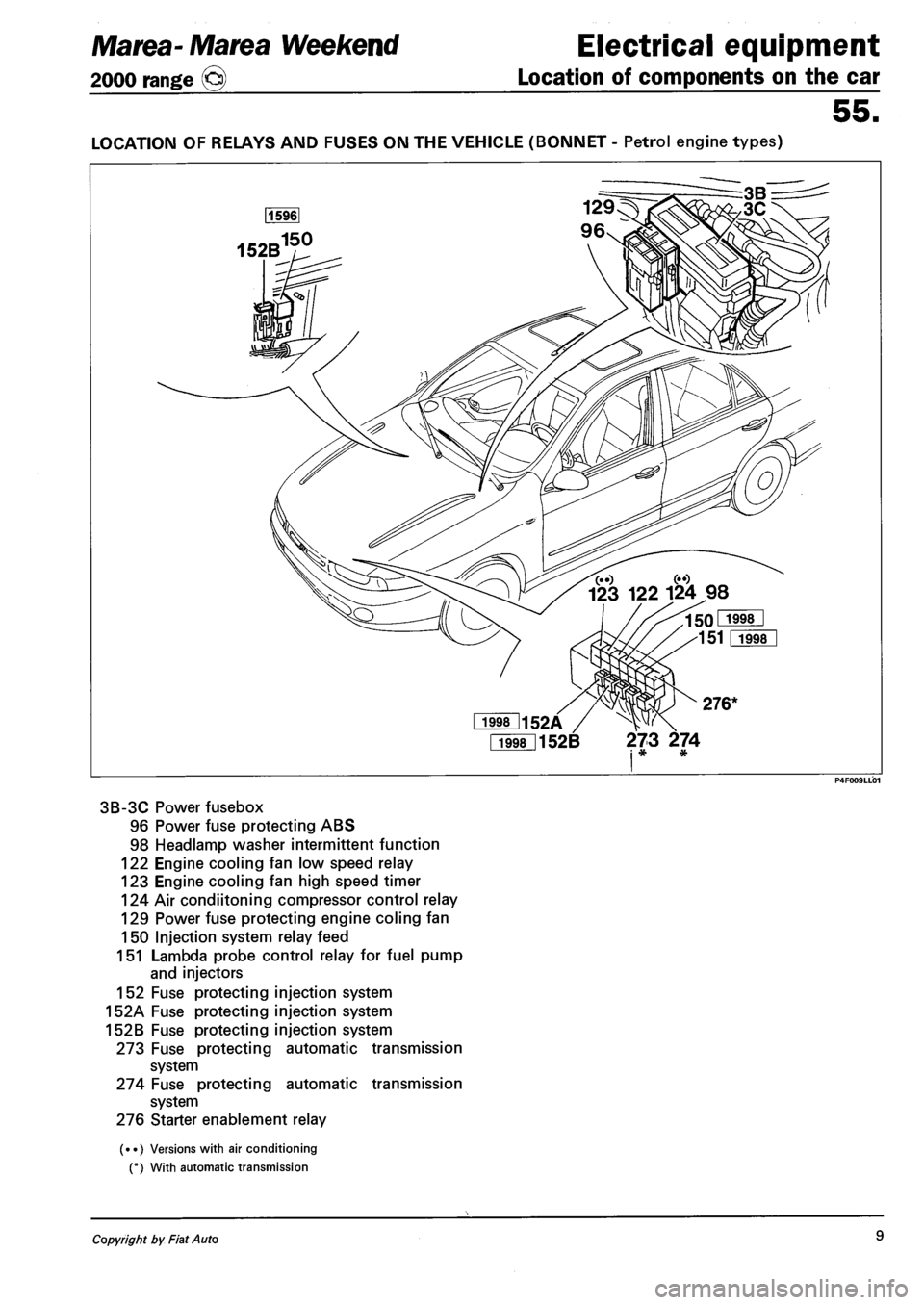
LOCATION OF RELAYS AND FUSES ON THE VEHICLE (BONNET - Petrol engine types)
Fi998l152B 273 274 i * *
3B-3C Power fusebox
96 Power fuse protecting ABS
98 Headlamp washer intermittent function
122 Engine cooling fan low speed relay
123 Engine cooling fan high speed timer
124 Air condiitoning compressor control relay
129 Power fuse protecting engine coling fan
150 Injection system relay feed
151 Lambda probe control relay for fuel pump
and injectors
152 Fuse protecting injection system
152A Fuse protecting injection system
152B Fuse protecting injection system
273 Fuse protecting automatic transmission
system
274 Fuse protecting automatic transmission
system
276 Starter enablement relay
(••) Versions with air conditioning
(*) With automatic transmission
Copyright by Fiat Auto 9
Page 256 of 330
Electrical equipment
Component location
Marea-Marea Weekend
2000 range ©
55.
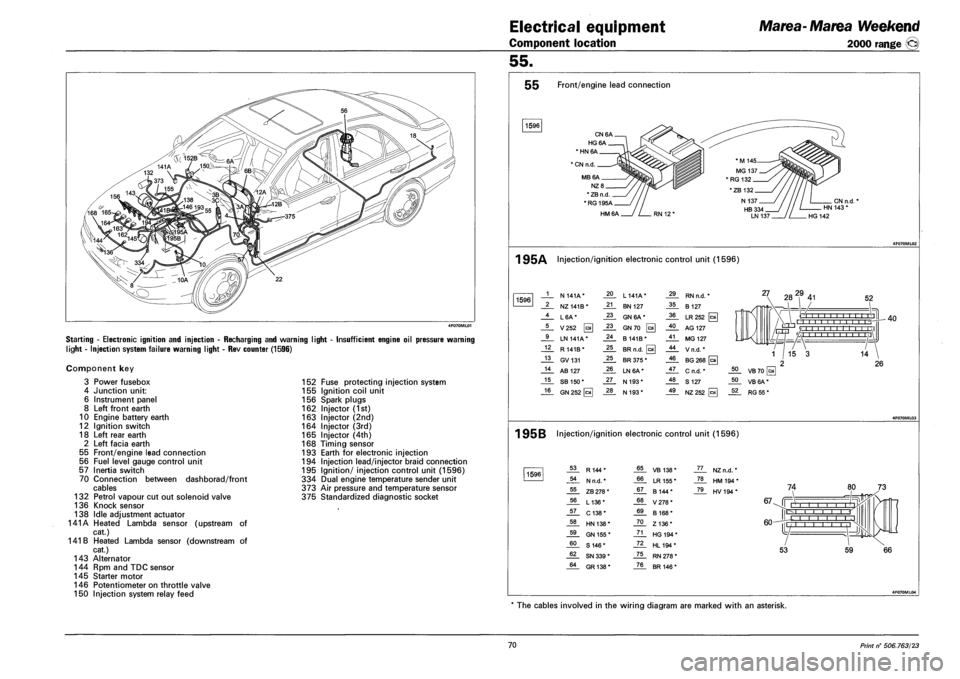
Starting - Electronic ignition and injection - Recharging and warning light
light - Injection system failure warning light - Rev counter (1596)
Insufficient engine oil pressure warning
Component key
3 Power fusebox
4 Junction unit:
6 Instrument panel
8 Left front earth
10 Engine battery earth
12 Ignition switch
18 Left rear earth
2 Left facia earth
55 Front/engine lead connection
56 Fuel level gauge control unit
57 Inertia switch
70 Connection between dashborad/front
cables
132 Petrol vapour cut out solenoid valve
136 Knock sensor
138 Idle adjustment actuator
141A Heated Lambda sensor (upstream of
cat.)
141 B Heated Lambda sensor (downstream of
cat.)
143 Alternator
144 Rpm and TDC sensor
145 Starter motor
146 Potentiometer on throttle valve
150 Injection system relay feed
152 Fuse protecting injection system
155 Ignition coil unit
156 Spark plugs
162 Injector (1st)
163 Injector (2nd)
164 Injector (3rd)
165 Injector (4th)
168 Timing sensor
193 Earth for electronic injection
194 Injection lead/injector braid connection
195 Ignition/ injection control unit (1596)
334 Dual engine temperature sender unit
373 Air pressure and temperature sensor
375 Standardized diagnostic socket
55 Front/engine lead connection
1596
CN6A.
HG6A.
* HN 6A
1 CN n.d.
MB6A.
NZ8_
* ZB n.d
*RG195A_
HM6A
CN n.d. HN 143 *
HG 142
1 95A Injection/ignition electronic control unit (1596)
1596 1 N 141A* 20 L 141A* 29 RN n.d. *
2 NZ141B* 21 BN 127 35 B 127
4 L6A* 23 GN 6A* 36 LR252 [c*
5 V252 0 23 GN70 0 40 AG 127
9 LN 141A* 24 B141B* 41 MG 127
12 R 141B* 25 BR n.d. 0 44 Vn.d.*
13 GV131 25 BR 375 * 46 BG 268 [a
14 AB 127 26 LN6A* 47 C n.d. *
15 SB 150* 27 N 193* 48 S 127
16 GN 252 [cal 28 N 193* 49 NZ252
27 282,9 41 52
O I I I I I I -r-r-r'n , , r'l -r-
rrrri '/ 1 1 1 1 1 1 1 1 1 1 1 \1 L/-HJ 'A i I I i i ,I
40
1 95B Injection/ignition electronic control unit (1596)
1596 53 R144* 65 VB 138* JL. NZn.d. *
54 N n.d. * 66 LR 155 * _ZL HM194*
55 ZB 278 * 67 B 144* _7JL HV194*
56 L136* 68 V278*
57 C138* 69 B 168*
58 HN 138* 70 Z136*
59 GN 155 * 71 HG 194 *
60 S 146* 72 HL194*
62 SN 339 * 75 RN 278 *
64 GR138* 76 BR 146 *
74
67-Jf Mill i i r r-l I I I
60-
IE
L -j |l
53 59
The cables involved in the wiring diagram are marked with an asterisk.
70 Print n° 506.763/23
Page 258 of 330
Electrical equipment
Component location
Marea-Marea Weekend
2000 range ®
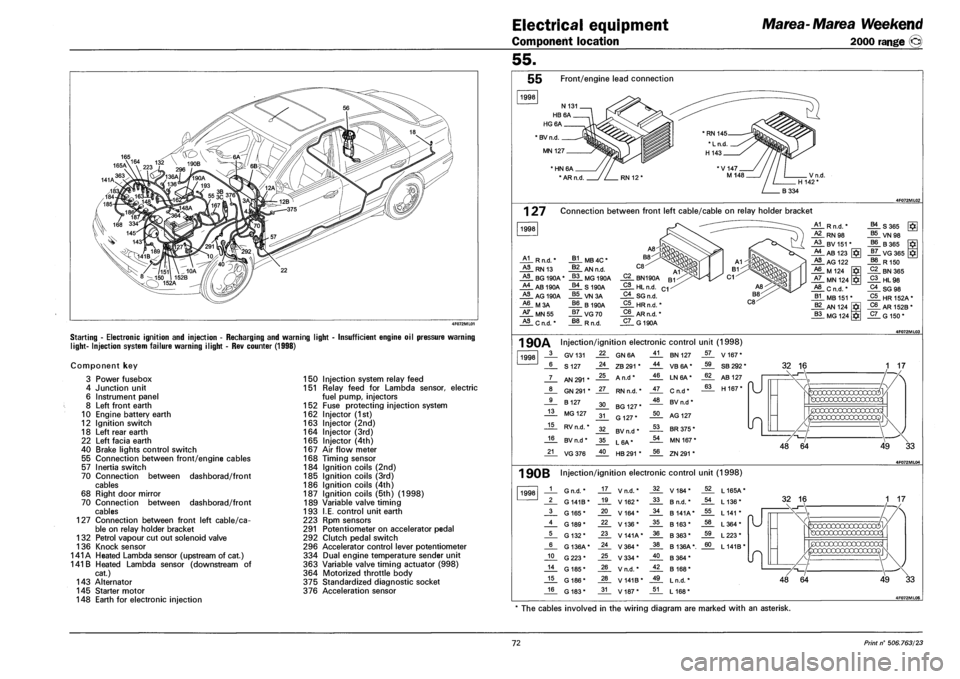
Starting - Electronic ignition and injection - Recharging and warning light
light- Injection system failure warning ilight - Rev counter (1998)
Insufficient engine oil pressure warning
Component key
3 Power fusebox
4 Junction unit
6 Instrument panel
8 Left front earth
10 Engine battery earth
12 Ignition switch
18 Left rear earth
22 Left facia earth
40 Brake lights control switch
55 Connection between front/engine cables
57 Inertia switch
70 Connection between dashborad/front
cables
68 Right door mirror
70 Connection between dashborad/front
cables
127 Connection between front left cable/ca
ble on relay holder bracket
132 Petrol vapour cut out solenoid valve
136 Knock sensor
141A Heated Lambda sensor (upstream of cat.)
141 B Heated Lambda sensor (downstream of
cat.)
143 Alternator
145 Starter motor
148 Earth for electronic injection
150 Injection system relay feed
151 Relay feed for Lambda sensor, electric
fuel pump, injectors
152 Fuse protecting injection system
162 Injector (1st)
163 Injector (2nd)
164 Injector (3rd)
165 Injector (4th)
167 Air flow meter
168 Timing sensor
184 Ignition coils (2nd)
185 Ignition coils (3rd)
186 Ignition coils (4th)
187 Ignition coils (5th) (1998)
189 Variable valve timing
193 I.E. control unit earth
223 Rpm sensors
291 Potentiometer on accelerator pedal
292 Clutch pedal switch
296 Accelerator control lever potentiometer
334 Dual engine temperature sender unit
363 Variable valve timing actuator (998)
364 Motorized throttle body
375 Standardized diagnostic socket
376 Acceleration sensor
55.
55 Front/engine lead connection
1998
* BV n.d
MN 127
' HN 6A
* AR n.d
1 27 Connection between front left cable/cable on relay holder bracket
1998
A1 R n.d.'
HL RN 13
HL BG 190A
A4 AB 190A
HL AG 190A
A6 M3A
HL MN55
HL C n.d. *
J*L MB 4C *
J*L AN n.d.
_§§_ MG 190A
_§£. S 190A
VN3A
66 B190A
_§7_ VG70
R n.d.
C2 BN190A
_2L HL n.d.
C4_ SG n.d.
C5 HRn.fi.'
C6 AR n.d. *
_5L G 190A
A1 R n.d. * B4 S365
HL RN98 B5 VN 98 A3 BV 151 * B6 B365 A4 AB 123 J7_ VG365 J*I
HL AG 122 B8 R 150 A6 M 124 C2 BN365 A7 MN 124 C3 HL98 A8 Cn.d.* C4 SG 98 B1 MB 151 * C5 HR152A* B2 AN 124 C6 AR 152B *
B3 MG 124 C7 G 150*
1 90A Injection/ignition electronic control unit (1998)
1998 3 GV131 22 GN6A 41 BN 127 57 V 167*
6 S 127 24 ZB 291 * 44 VB6A* 59 SB 292 *
7 AN 291 * 25 A n.d* 46 LN6A* 62 AB 127
"U 8 GN 291 * 27 RN n.d. * 47 Cn.d* 63 H 167* "U
9 B 127 30 BG 127 * 48 BV n.d *
13 MG 127 31 G 127* 50 AG 127
15 RV n.d. * 32 BV n.d * 53 BR 375 *
16 BV n.d * 35 L6A* 54 MN 167 *
21 VG376 40 HB 291 * 56 ZN 291 *
32 16
49 33
1 90B Injection/ignition electronic control unit (1998)
1998 1 G n.d. * 17 V n.d. * 32 V184* 52 L165A*
2 G 141B* 19 V162* 33 B n.d. * 54 L 136*
3 G 165* 20 V164* 34 B 141A* 55 L 141 *
4 G 189* 22 V136* 35 B 163* 58 L364*
5 G 132* 23 V141A* 36 B363* 59 L223*
6 G 136A* 24 V364* 38 B 136A*. 60 L141B*
10 G223* 25 V334* 40 B364*
14 G 185* 26 V n.d. * 42 B 168*
15 G 186* 28 V 141B* 49 L n.d. *
16 G 183* 31 V187* 51 L 168*
49 33
* The cables involved in the wiring diagram are marked with an asterisk.
72 Print n° 506.763/23
Page 260 of 330
Electrical equipment
Component location
Marea-Marea Weekend
2000 range ©
55.
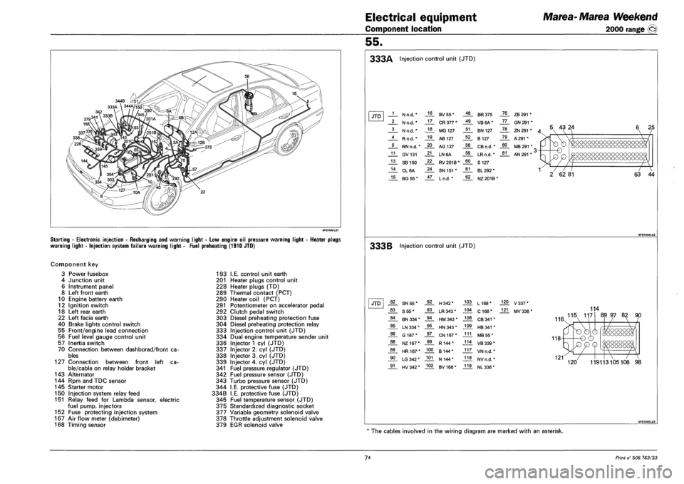
Starting - Electronic injection - Recharging and warning light - Low engine oil pressure warning
warning light - Injection system failure warning light - Fuel preheating (1910 JTD)
ight - Heater plugs
Component key
3 Power fusebox
4 Junction unit
6 Instrument panel
8 Left front earth
10 Engine battery earth
12 Ignition switch
18 Left rear earth
22 Left facia earth
40 Brake lights control switch
55 Front/engine lead connection
56 Fuel level gauge control unit
57 Inertia switch
70 Connection between dashborad/front ca
bles
127 Connection between front left ca
ble/cable on relay holder bracket
143 Alternator
144 Rpm and TDC sensor
145 Starter motor
150 Injection system relay feed
151 Relay feed for Lambda sensor, electric
fuel pump, injectors
152 Fuse protecting injection system
167 Air flow meter (debimeter)
168 Timing sensor
193 I.E. control unit earth
201 Heater plugs control unit
228 Heater plugs (TD)
289 Thermal contact (PCT)
290 Heater coil (PCT)
291 Potentiometer on accelerator pedal
292 Clutch pedal switch
303 Diesel preheating protection fuse
304 Diesel preheating protection relay
333 Injection control unit (JTD)
334 Dual engine temperature sender unit
336 Injector 1 cyl (JTD)
337 Injector 2. cyl (JTD)
338 Injector 3. cyl (JTD)
339 Injector 4. cyl (JTD)
341 Fuel pressure regulator (JTD)
342 Fuel pressure sensor (JTD)
343 Turbo pressure sensor (JTD)
344 I.E. protective fuse (JTD)
334B I.E. protective fuse (JTD)
345 Fuel temperature sensor (JTD)
375 Standardized diagnostic socket
377 Variable geometry solenoid valve
378 Throttle adjustment solenoid valve
379 EGR solenoid valve
333A Injection control unit (JTD)
JTD 1 N n.d. * 16 BV55* 48 BR 375 76 ZB 291 *
2 N n.d. * 17 CR 377 * 49 VB6A* 77 GN 291 *
3 N n.d. * 18 MG 127 51 BN 127 78 ZN 291 * A 4 Rn.d.* 19 AB 127 52 B 127 79 A 291 *
5 RN n.d. * 20 AG 127 58 CB n.d. * 80 MB 291 * ,
11 GV131 21 LN6A 59 LRn.d. * 81 AN 291 * ' >
13 SB 150 22 RV201B* 60 S 127
14 CL6A 24 SN 151 * 61 BL 292 * 1
15 BG55* 47 Ln.d. * 62 NZ 201B*
5 43 24
-o
T7
2 62 81
oooooooooooooooooc oooooooooooooooooc
oooooooooooooooooc oooooooooooooooooc
~7
63 44
333B Injection control unit (JTD)
JTD 82 SN55* 92 H342* 103 L168* 120 V337*
83 S55* 93 LR 343* 104 C 168* 121 MV 338 *
84 BN 334 * 94 HM 343 * 108 CB 341 *
85 LN 334 * 95 HN 343 * 109 HB 341 *
86 G 167* 97 CN 167* 111 MB 55*
88 NZ167* 99 R144* 114 VB 339 *
89 HR167* 100 B 144* 117 VN n.d. *
90 LG 342 * 101 N 144* 118 NVn.d. *
91 HV 342 * 102 BV168* 119 NL 336 *
114
AA 115 117
116.
89 97 82 90
oooooc OOOOOOG OOOOOOO 'OOOOOC
119113105106 98
* The cables involved in the wiring diagram are marked with an asterisk.
74 Print n° 506.763/23
Page 262 of 330
Electrical equipment
Component location
Marea-Marea Weekend
2000 range ©
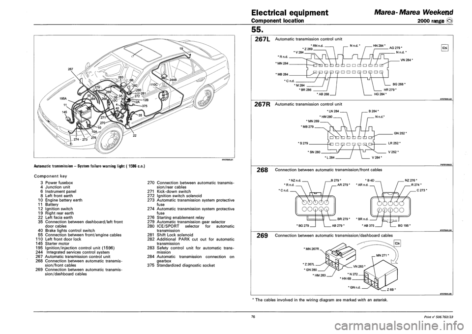
Automatic transmission - System failure warning light ( 1596 c.a.)
Component key
3 Power fusebox
4 Junction unit
6 Instrument panel
8 Left front earth
10 Engine battery earth
11 Battery
12 Ignition switch
19 Right rear earth
22 Left facia earth
35 Connection between dashboard/left front
door cables
40 Brake lights control switch
55 Connection between front/engine cables
110 Left front door lock
145 Starter motor
195 Ignition/injection control unit (1596)
244 Integrated services control system
267 Automatic transmission control unit
268 Connection between automatic transmis
sion/front cables
269 Connection between automatic transmis
sion/dashboard cables
270 Connection between automatic transmis
sion/rear cables
271 Kick-down switch
272 Ignition switch solenoid
273 Automatic transmission system protective
fuse
274 Automatic transmission system protective
fuse
276 Starting enablement relay
279 Automatic transmission gear selector
280 ICE/SPORT selector for automatic
transmission
281 Shift Lock solenoid
282 Additional PARK cut out for automatic
transmission
283 Safety control unit for automatic trans
mission
284 Automatic transmission connection on
gearbox
375 Standardized diagnostic socket
55.
267L Automatic transmission control unit
*RNn.d , . Nn.d.' HN 284 * *Z269 'V284
AG 279 *
N n.d.'
OS
VN 284*
* MB 284
* C n.d.
M284
• BR 286
BG 268'
HR 279 *
* AB 268 HG 284 *
267R Automatic transmission control unit
* LN 284
' HM 280
* MN 269
' MB 279
* S 279.
GN 252'
* SN 280.
L284 / \ V284*
LR 252 *
V252*
268 Connection between automatic transmission/front cables
B 279 *
AR 279 *
*B4D NZ 276 *
• AR n.d
' BG 279 AB 279 * BG 195'
269 Connection between automatic transmission/dashboard cables
' MN 267R
The cables involved in the wiring diagram are marked with an asterisk.
76 Print n° 506.763/23
Page 297 of 330
Marea- Marea Weekend
2000 range ©
Electrical equipment
Connector blocks
55.
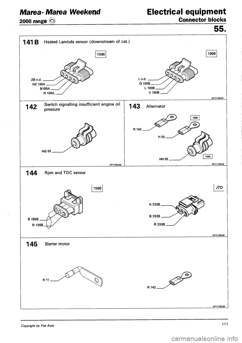
1 41 B Heated Lambda sensor (downstream of cat.)
ZB n.d.
NZ195A
1998
Ln.d.
G190B
B195A
R195A
L 190B
V190B
142 Switch signalling insufficient engine oil
pressure
HG55
143 Alternator
R145
HN55
1 44 RPm and TDC sensor
B195B
1596
N333B
R1QSR ' '
1 45 Starter motor
R11
R143
JTD
Copyright by Fiat Auto 111
Page 298 of 330
Electrical equipment
Connector blocks
Marea-Marea Weekend
2000 range ©
55.
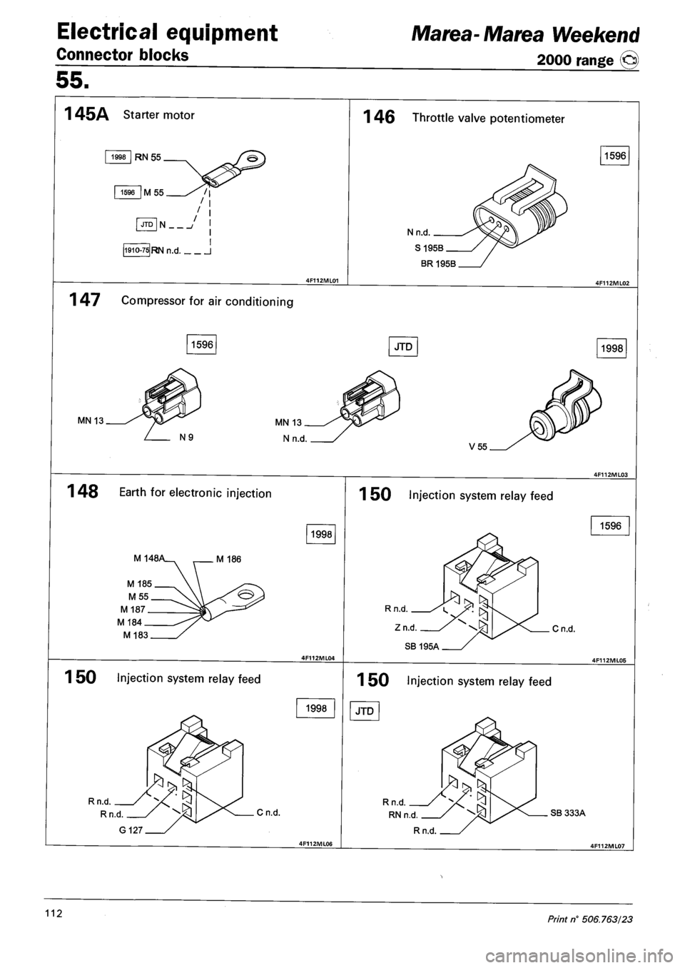
1 45A Starter motor
1998 RN 55
1596 M 55 / I
JTD N /
1910-75 RN n.d I
1 46 Throttle valve potentiometer
N n.d.
S 195B
BR195B
1596
1 47 Compressor for air conditioning
1596 JTD 1998
MN 13
V55
1 48 Earth for electronic injection
1998
M 148, M 186
M 183
1 50 Injection system relay feed
1998
Cn.d.
150 Injection system relay feed
1596
Cn.d.
1 50 Injection system relay feed
JTD
Rn.d
RNn.d SB 333A
Rn.d.
112 Print n° 506.763/23