fiat marea 1998 FIAT MAREA 2001 1.G Workshop Manual
[x] Cancel search | Manufacturer: FIAT, Model Year: 2001, Model line: MAREA, Model: FIAT MAREA 2001 1.GPages: 330
Page 10 of 330
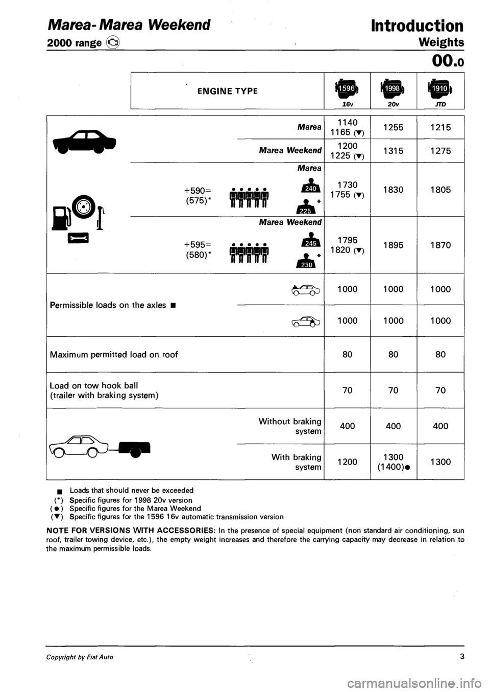
Marea- Marea Weekend
2000 range @
Introduction
Weights
ENGINE TYPE
16v 20v
OO.o
Marea
Marea Weekend
+590=
(575)' ¥¥¥¥¥
Marea
+595=
(580)*
Marea Weekend
mrirnT
1140
1165 (•)
1200
1225 (•)
1730
1755 (T)
1795
1820 (T)
1255
1315
1830
1895
1000 1000
Permissible loads on the axles
1000 1000
Maximum permitted load on roof 80 80
Load on tow hook ball
(trailer with braking system) 70 70
Without braking
system 400 400
With braking
system 1200 1300
(1400)«
I Loads that should never be exceeded
(*) Specific figures for 1998 20v version
(•) Specific figures for the Marea Weekend
(T) Specific figures for the 1596 16v automatic transmission version
NOTE FOR VERSIONS WITH ACCESSORIES: In the presence of special equipment (non standard air conditioning, sun
roof, trailer towing device, etc.), the empty weight increases and therefore the carrying capacity may decrease in relation to
the maximum permissible loads.
Copyright by Fiat Auto 3
Page 78 of 330
Marea- Marea Weekend & Engine
2000 range (§) Fuel feed system
ENGINE MANAGEMENT SYSTEM
Foreword
The Marea-Marea Weekend 1998 20v is equipped with a 5 cylinder in line engine with 20 valves, 1998
cc, twin overhead camshaft and a Bosch ME3.1 integrated electronic injection/ignition system.
The fuel system differs from the one described for the 1998 20v "99 range" version through the addition
of several variants to make it compatible with the EEC Stage 3 EOBD regulations.
The main modifications to the system can be summarized as follows:
- Catalytic converter near the exhaust manifold to take maximum advantage of the heat of the gases.
- Two Lambda sensors, one upstream (front) and one downstream (rear) which check the quality of the
exhaust gases and the operation of the catalyzer.
- Adoption of an accelerometre sensor on the right shock absorber turret, used to distinguish between
engine torque variations doe to the uneveness of the road surface and those due to failed ignition in
the combustion chamber (misfire).
- Adoption of a timing sensor on the inlet side timing pulley.
- Multi-purpose valve on the tank to prevent leaks.
- Adoption of raipd attachment connectors for the anti-evaporation system pipes.
- Cap on the fuel filler with an attachment cable.
For further information on the fuel system, refer to publication 507137.
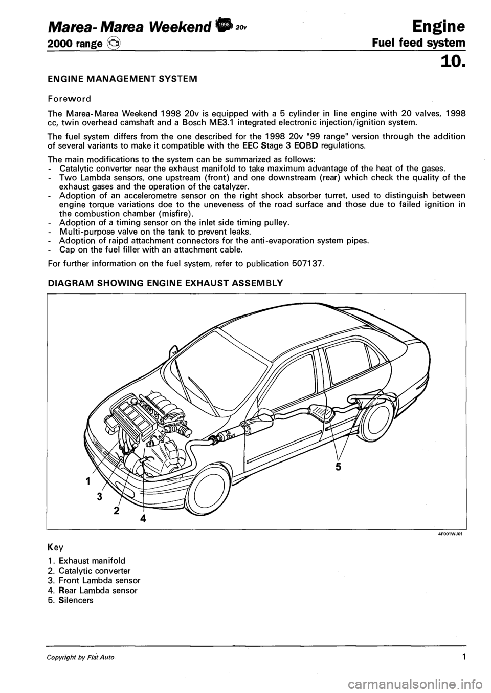
DIAGRAM SHOWING ENGINE EXHAUST ASSEMBLY
4F001WJ01
Key
1. Exhaust manifold
2. Catalytic converter
3. Front Lambda sensor
4. Rear Lambda sensor
5. Silencers
Copyright by Fiat Auto 1
Page 125 of 330
Marea- Marea Weekend
2000 range CJ
Auxiliary Units
Index
Compressor ( 1596 engine)
Compressor ( 1910 JTD)
Compressor ( 1998 engine)
Specifications
50
page
1
2
3
4
FOR ANYTHING NOT DEALT WITH,
REFER TO THE BASIC MANUAL, SECTION 50.
Copyright by Fiat Auto
Page 128 of 330
Marea-Marea Weekend
2000 range ©)
Auxiliary Units
Climate control
50
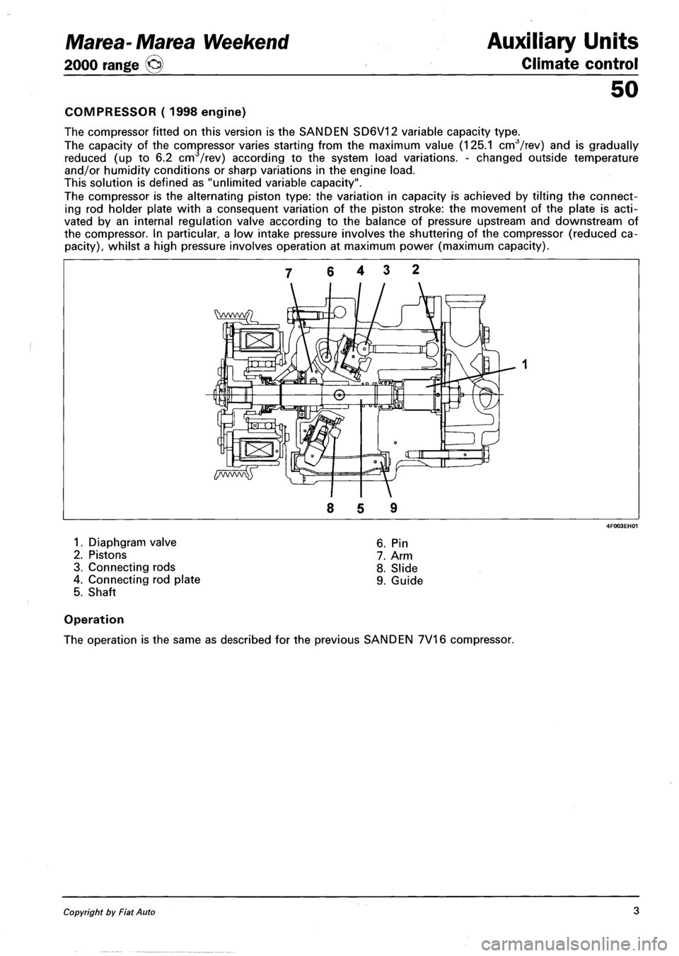
COMPRESSOR ( 1998 engine)
The compressor fitted on this version is the SANDEN SD6V12 variable capacity type.
The capacity of the compressor varies starting from the maximum value (125.1 cnrfVrev) and is gradually
reduced (up to 6.2 cm /rev) according to the system load variations. - changed outside temperature
and/or humidity conditions or sharp variations in the engine load.
This solution is defined as "unlimited variable capacity".
The compressor is the alternating piston type: the variation in capacity is achieved by tilting the connect
ing rod holder plate with a consequent variation of the piston stroke: the movement of the plate is acti
vated by an internal regulation valve according to the balance of pressure upstream and downstream of
the compressor. In particular a low intake pressure involves the shuttering of the compressor (reduced ca
pacity), whilst a high pressure involves operation at maximum power (maximum capacity).
1. Diaphgram valve
2. Pistons
3. Connecting rods
4. Connecting rod plate
5. Shaft
6. Pin
7. Arm
8. Slide
9. Guide
Operation
The operation is the same as described for the previous SANDEN 7V16 compressor.
Copyright by Fiat Auto 3
Page 131 of 330
Marea- Marea Weekend
2000 range ©
Electrical equipment
Protection and security devices
55.
PROTECTION AND SAFETY DEVICES
All the vehicle supply lines were designed taking into account the most up-to-date directives in terms of
safety and protection, especially to prevent fires.
There are 2 types of protection:
- active protection, aims to reduce the causes of faults "at source"
- passive protection, aims to limit the effects of a fault as much as possible
The first category includes a carefully designed wiring layout with wires positioned and carefully anchored
on tracks that are repaired and protected if necessary.
The cables connected to the alternator and the motor were modified for this reason by adding protective
caps etc. A strengthened sheath was also introduced for some of the more exposed sections of wiring.
The passive protection includes all interventions to reduce faults due to high current (overload, short cir
cuit).
All system fuses were rated based on the nominal absorbtion of the loads activated at the same time, to
ensure intervention in cases of a clear short circuit.
The introduction of a box containing 4 maxifuses with other fuses connected on the outside means all
the supplies can be protected except for the cable that connects the battery to the starter motor and the
cable that connects the starter motor to the recharging alternator. These cables are therefore protected by a
strengthened supplementary sheath.
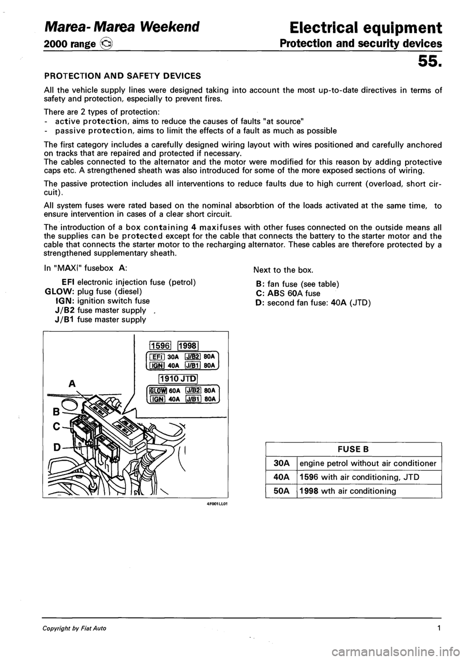
In "MAXI" fusebox A:
EFI electronic injection fuse (petrol)
GLOW: plug fuse (diesel)
IGN: ignition switch fuse
J/B2 fuse master supply .
J/B1 fuse master supply
Next to the box.
B: fan fuse (see table)
C: ABS 60A fuse
D: second fan fuse: 40A (JTD)
115961 1998
iFil 30A IJ/B21 BOA
fiGNl 4OA IJTBTI BOA
1910JTD
IGLOWl 60A P7B21 80A
MGNI 40A IJ/Bll 80A
FUSE B
30A engine petrol without air conditioner
40A 1596 with air conditioning, JTD
50A 1998 wth air conditioning
Copyright by Fiat Auto 1
Page 211 of 330
Marea-Marea Weekend
2000 range ©
Electrical equipment
Wiring diagrams
55.
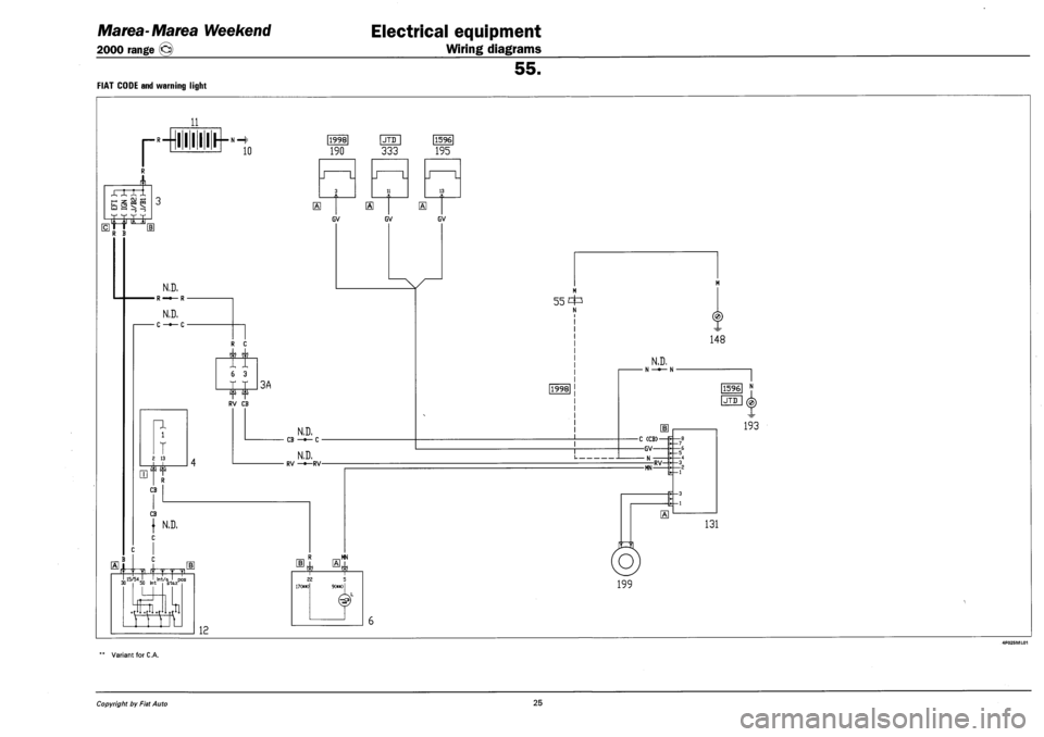
FIAT CODE AND WARNING LIGHT
r
-rife-
HL
M =s
c I« § LZ!
LlJ
i^1 !jj it t
R B [1
N,D,
•R-«—R-
N.D.
• c -•— c •
n
1
LTJ
T 13
ijr
2 13
74T"
CB
CB
( N.D,
EL thf 4 T T ? J 15/54J I Int/Q I DQ5 „ 15/54 I , I Int/a J pos 30 50 Int stazK
n., ,ti
12
•N—(|i
10
f ?
i 3
4 i 4 i 3A
|1998|
190
LJTDJ
333
|1596|
195
GV
N.D. CB —•— C -
N.D. RV —•—RV-
MN
J L J L J L
1 3
] El
GV GV
55 c4=s N
1998
1
N.D, N -*- N
•C (CB>-
—GV—
— N •
-MN RV-
0
O
199
148
[1596] N
IJTD I (4
193
131
Variant for C.A.
Copyright by Fiat Auto 25
Page 212 of 330
4F026ML01
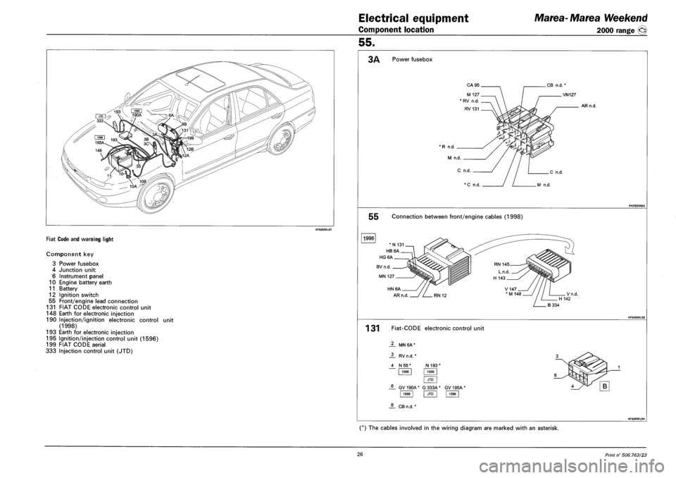
FIAT CODE AND WARNING LIGHT
Component key
3 Power fusebox
4 Junction unit:
6 Instrument panel
10 Engine battery earth
11 Battery
12 Ignition switch
55 Front/engine lead connection
131 FIAT CODE electronic control unit
148 Earth for electronic injection
190 Injection/ignition electronic control unit
(1998)
193 Earth for electronic injection
195 Ignition/injection control unit (1596)
199 FIAT CODE aerial
333 Injection control unit (JTD)
Electrical equipment Marea-Marea Weekend
Component location 2000 range @
55.
3A Power fusebox
* R n.d. _
M n.d.
C
VN127
ARn.d.
P4F834IM02
55 Connection between front/engine cables (1998)
1998
4F026ML03
131 Fiat-CODE electronic control unit
MN 6A *
1998 JTD 1596
JL CBn.d. *
4F026ML04
(*) The cables involved in the wiring diagram are marked with an asterisk.
26 Print n° 506.763/23
Page 233 of 330
Marea-Marea Weekend
2000 range ©
Electrical system
Wiring diagrams
55.
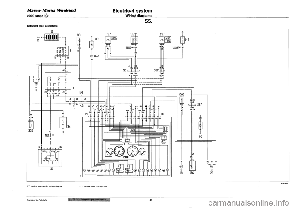
INSTRUMENT PANEL CONNECTIONS
11
10 L- 1 I
88 137
xnrx _, -, ru --;
IZT
BN
89
N N NZ
AR
GV
335
I I
1 2
~1 4, -A 1 9 10
T nT T 13 4 10 1 11 2
|1596
_n_
MG
3341
f i 1,
137
J~L
tp89A
BR
LN
119981 (B) HB
I HB
CN
[TJT T T T T rj]T R CB AB AV AV AG
•AB -AG -GV
—PI—LB—l—AG •LB -AG -GV
AG-AG-
70 m
~ AR
A.
CB
N.D,f-c
l
C
J
3A
frr 4 r T ?
I 15/54 J. . Jnt/o J DOS
.El J 15/54 I . Jnt/a ' pos 3D 50 int stazr
U.JJ1
12
BN
55 c MG r i HG 1 -{ } HM H J
| JTD
|1998|
IL
3
NZ HM
HM CN
55CC
NZ
CN
©)^AG
HG,
|CN
m
HB
NZ HG HMl CNlNZ
-HJ I I
HM
1 2 3 * 5 6 7 8 9 10111213 1415161718
GV BN1
Hct
1 2 3 4 5 6 7 8 9 10 U121314151*17181920 212223242526
H3
y> y y fiS) fcp M
n fi
@ © ® w W ©
o
L,.-,, ..,,,1
IT
|1998|
262
SI
N
18
HG BN
4
NZ
3 28A
NZ HG BN
BN
JL
90
NZ
HG
56
NZ N N
22
A.T. version: see specific wiring diagram • Variant from January 2001
Copyright by Fiat Auto XII-00 - Supersedes previous version 47
Page 241 of 330
Marea-Marea Weekend
2000 range ©)
Electrical equipment
Wiring diagrams
55.
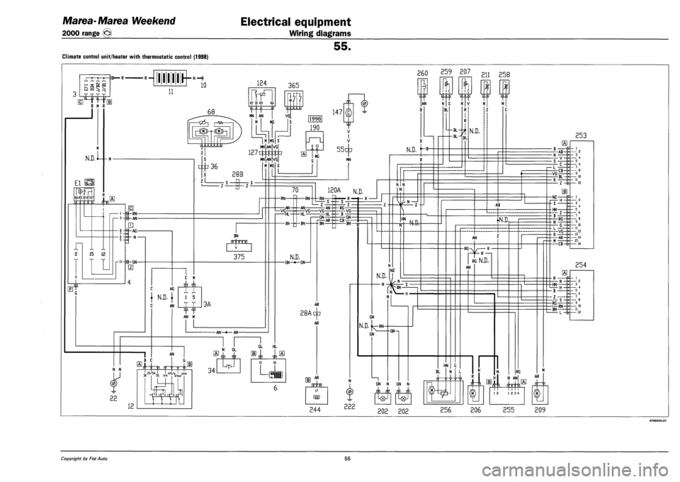
Climate control unit/heater with thermostatic control (1998)
.-,
B M R
N.D.
El
86 85 30 87 87
n i 2 15 12
i-B-RN-3-fg-AN-
LTJ
j—AG-
h N -
r-w-f^GN-
•R — lllllr-»H 260
11
10 124
87 30 85 86
68
365
-cz5-| |—vw-
|-K®H-I®r-|
MN | AN |
M MG
VG
MN
127^:
36
MN
zL
28B
MG
AN
AN
BN
fffrn?
375
AG
{ N.D, {
AN
C M
l 5
AN M
3A
-AN—•— AN-
1X1,
147
|1998|
190
JI
VG
VG
MG
6 13
f-55
MG
IT
V I V
+
MN
AN
B
259 207 2n 25g
N.D,
70
-RN-
VG; -AN-
-RN-
120A N.D,
-RN-
•AN-VG -Vb -GN
-AN
HL-
N.D. -GN—•—GN—1
BN AR
-RG--VG--
-CB GN-
-BN-
AR
28AtI?
AR
AN
N N
22
B C
12
n 15/54.1 . I Irrt/a J pos 50 Irrt
31
staz' 34
N GL
11 11
-T-
GL HL
CI 1
I—frai j AR
•> N Z __L
HN
N.D.
— N -
NZ
MB,
N
GN
N.D, j^RN-
GN
17
m
N
(2>)
222
GN—i
ft rr ft
BL
^BL-rl
BL^IBL
1ST
N.D.
HN
BL
GN N GN N
£1 £1
AB
N.D
AN
-RG-R —
RG N.D.
AN
N
4-
RG
253
-AB-
r— L
-VG CB-
BL-
-NZ-
- S -
-HN-
-RG-
l~—--CB-
254
-HN-
- B -
- Z -
-RG
-BN-RN-
N AN
r|"|"|" i m
AR
12 12 3 4
202 202 256 206 255 209
Copyright by Fiat Auto 55
Page 249 of 330
Marea-Marea Weekend
2000 range ©
Electrical equipment
Wiring diagrams
55.
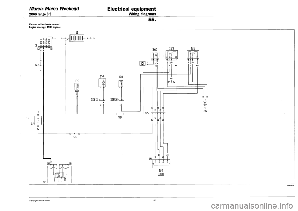
Version with climate control
Engine cooling ( 1998 engine)
11
—. -r
J ^ if tr
R —R
R B
N.D,
J
3A
?
(
J RV
I I I I I I H 10
1
0
129
P-,
-RV •—RV-
N.D.
12
fTT ry r 'f f n
154 170
128 St
IZ\1
i 128 He
N.D,
365 123
BN
37 30 86 85
N I RV |
M AB
RV
RV-i-RV-
RV BN AG AB
127 c
B AB RV BN AG
1 BN B I AB AG
•I i i 9 41 62 50
n n
190
|1998|
122
87 30 86 85
N I RV I
L AG
N N
I N I
8A
Copyright by Fiat Auto 63