Bar FIAT MAREA 2001 1.G User Guide
[x] Cancel search | Manufacturer: FIAT, Model Year: 2001, Model line: MAREA, Model: FIAT MAREA 2001 1.GPages: 330
Page 63 of 330
Marengo 0 ™ Technical Data
2000 range Suspension and wheels
OO.o
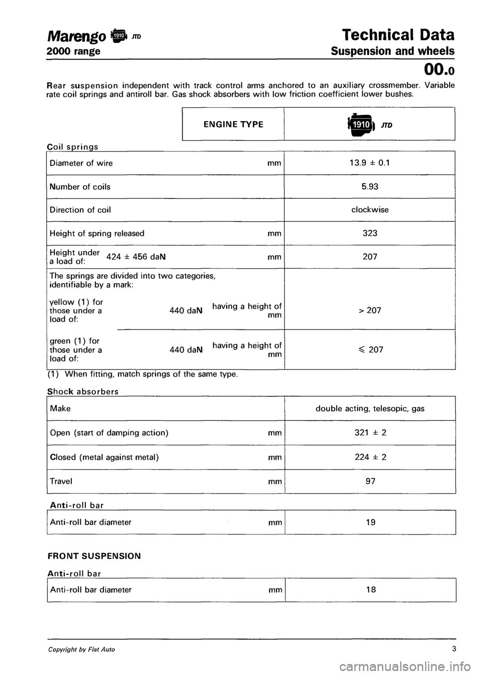
Rear suspension independent with track control arms anchored to an auxiliary crossmember. Variable
rate coil springs and antiroll bar. Gas shock absorbers with low friction coefficient lower bushes.
ENGINE TYPE
Coil springs
Diameter of wire mm 13.9 ± 0.1
Number of coils 5.93
Direction of coil clockwise
Height of spring released mm 323
Height under 424 ± 456 daN mm a load of : 207
The springs are divided into two categories,
identifiable by a mark:
XX°l 440 daN having a heigh, of i -i x mm load of:
> 207
green (1) for having a height of those under a 440 daN a a i J x. mm load of:
^ 207
(1) When fitting, match springs of the same type.
Shock absorbers
Make double acting, telesopic, gas
Open (start of damping action) mm 321 ± 2
Closed (metal against metal) mm 224 ± 2
Travel mm 97
Anti-roll bar
Anti-roll bar diameter mm 19
FRONT SUSPENSION
Anti-roll bar
Anti-roll bar diameter mm 18
Copyright by Fiat Auto 3
Page 87 of 330
Marea- Marea Weekend © ™ Engine
2000 range Q Fuel feed system
10.
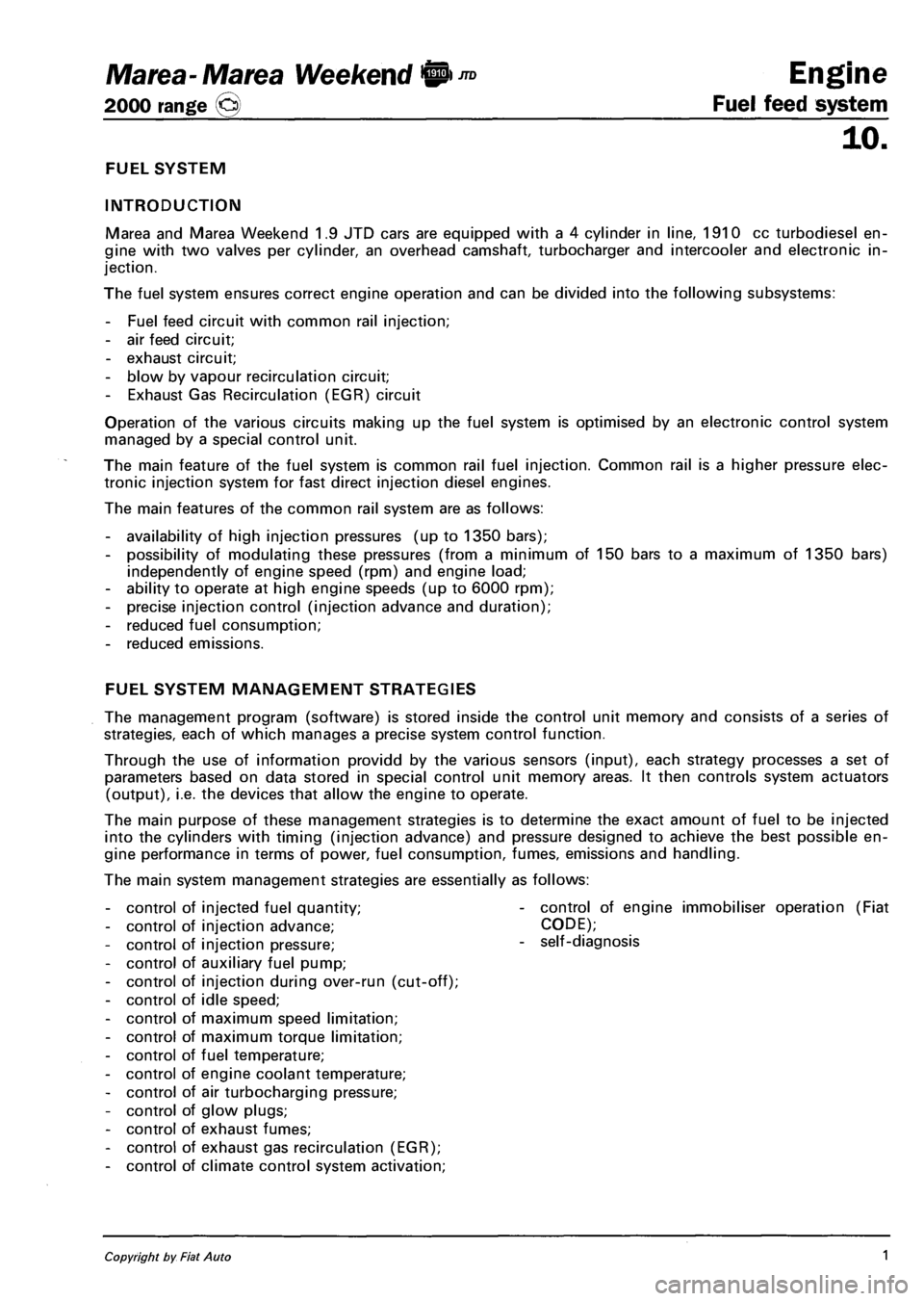
FUEL SYSTEM
INTRODUCTION
Marea and Marea Weekend 1.9 JTD cars are equipped with a 4 cylinder in line, 1910 cc turbodiesel en
gine with two valves per cylinder, an overhead camshaft, turbocharger and intercooler and electronic in
jection.
The fuel system ensures correct engine operation and can be divided into the following subsystems:
- Fuel feed circuit with common rail injection;
- air feed circuit;
- exhaust circuit;
- blow by vapour recirculation circuit;
- Exhaust Gas Recirculation (EGR) circuit
Operation of the various circuits making up the fuel system is optimised by an electronic control system
managed by a special control unit.
The main feature of the fuel system is common rail fuel injection. Common rail is a higher pressure elec
tronic injection system for fast direct injection diesel engines.
The main features of the common rail system are as follows:
- availability of high injection pressures (up to 1350 bars);
- possibility of modulating these pressures (from a minimum of 150 bars to a maximum of 1350 bars)
independently of engine speed (rpm) and engine load;
- ability to operate at high engine speeds (up to 6000 rpm);
- precise injection control (injection advance and duration);
- reduced fuel consumption;
- reduced emissions.
FUEL SYSTEM MANAGEMENT STRATEGIES
The management program (software) is stored inside the control unit memory and consists of a series of
strategies, each of which manages a precise system control function.
Through the use of information providd by the various sensors (input), each strategy processes a set of
parameters based on data stored in special control unit memory areas. It then controls system actuators
(output), i.e. the devices that allow the engine to operate.
The main purpose of these management strategies is to determine the exact amount of fuel to be injected
into the cylinders with timing (injection advance) and pressure designed to achieve the best possible en
gine performance in terms of power, fuel consumption, fumes, emissions and handling.
The main system management strategies are essentially as follows:
contro
contro
contro
contro
contro
contro
contro
contro
contro
contro
contro
contro
contro
contro
contro
of injected fuel quantity;
of injection advance;
of injection pressure;
of auxiliary fuel pump;
of injection during over-run (cut-off);
of idle speed;
of maximum speed limitation;
of maximum torque limitation;
of fuel temperature;
of engine coolant temperature;
of air turbocharging pressure;
of glow plugs;
of exhaust fumes;
of exhaust gas recirculation (EGR);
of climate control system activation;
control of engine immobiliser operation (Fiat
CODE);
self-diagnosis
Copyright by Fiat Auto 1
Page 89 of 330
Ma tea- Marea Weekend 9 ™
2000 range (Q) Fuel feed system
Engine
10.
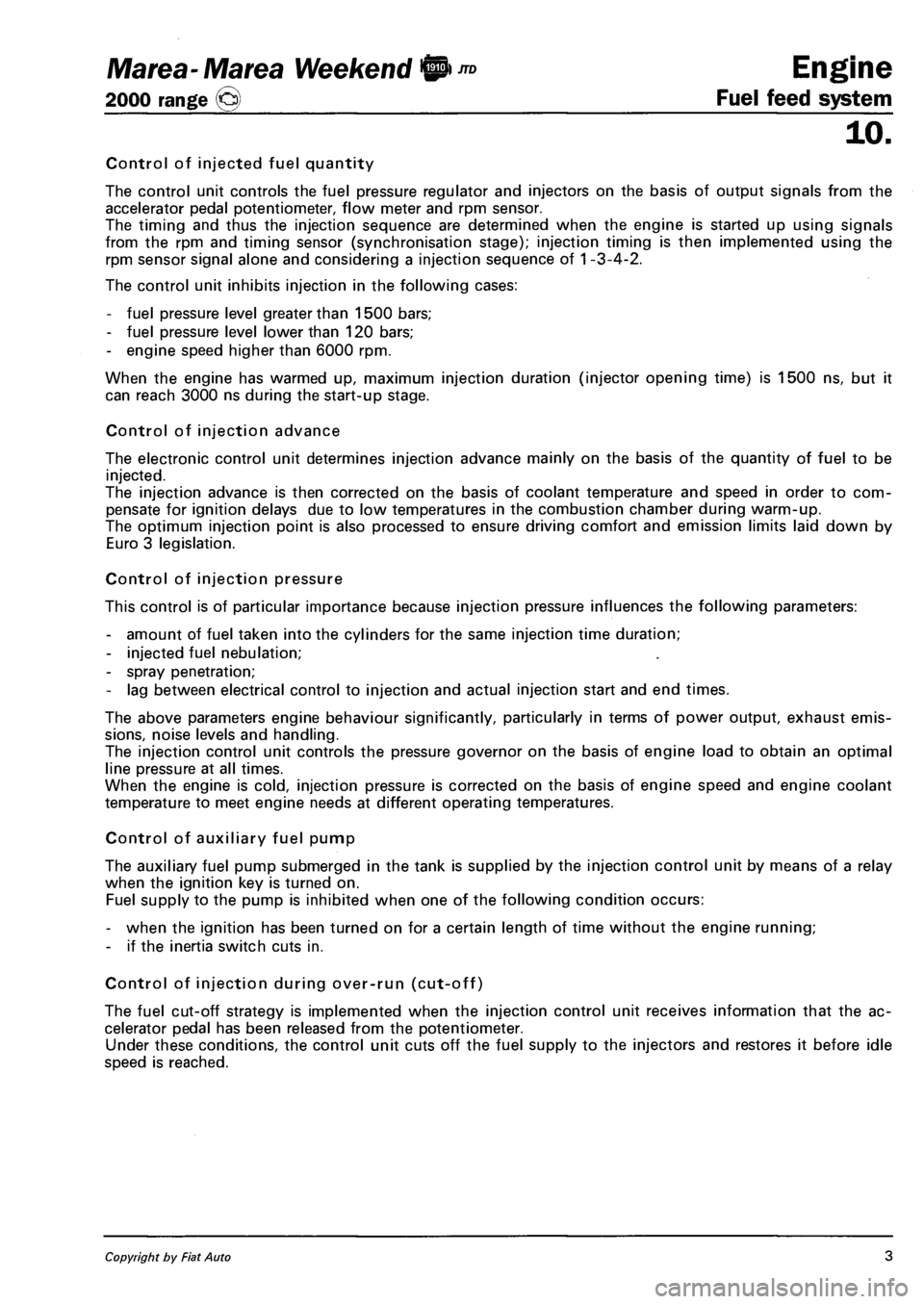
Control of injected fuel quantity
The control unit controls the fuel pressure regulator and injectors on the basis of output signals from the
accelerator pedal potentiometer, flow meter and rpm sensor.
The timing and thus the injection sequence are determined when the engine is started up using signals
from the rpm and timing sensor (synchronisation stage); injection timing is then implemented using the
rpm sensor signal alone and considering a injection sequence of 1 -3-4-2.
The control unit inhibits injection in the following cases:
- fuel pressure level greater than 1500 bars;
- fuel pressure level lower than 120 bars;
- engine speed higher than 6000 rpm.
When the engine has warmed up, maximum injection duration (injector opening time) is 1500 ns, but it
can reach 3000 ns during the start-up stage.
Control of injection advance
The electronic control unit determines injection advance mainly on the basis of the quantity of fuel to be
injected.
The injection advance is then corrected on the basis of coolant temperature and speed in order to com
pensate for ignition delays due to low temperatures in the combustion chamber during warm-up.
The optimum injection point is also processed to ensure driving comfort and emission limits laid down by
Euro 3 legislation.
Control of injection pressure
This control is of particular importance because injection pressure influences the following parameters:
- amount of fuel taken into the cylinders for the same injection time duration;
- injected fuel nebulation;
- spray penetration;
- lag between electrical control to injection and actual injection start and end times.
The above parameters engine behaviour significantly, particularly in terms of power output, exhaust emis
sions, noise levels and handling.
The injection control unit controls the pressure governor on the basis of engine load to obtain an optimal
line pressure at all times.
When the engine is cold, injection pressure is corrected on the basis of engine speed and engine coolant
temperature to meet engine needs at different operating temperatures.
Control of auxiliary fuel pump
The auxiliary fuel pump submerged in the tank is supplied by the injection control unit by means of a relay
when the ignition key is turned on.
Fuel supply to the pump is inhibited when one of the following condition occurs:
- when the ignition has been turned on for a certain length of time without the engine running;
- if the inertia switch cuts in.
Control of injection during over-run (cut-off)
The fuel cut-off strategy is implemented when the injection control unit receives information that the ac
celerator pedal has been released from the potentiometer.
Under these conditions, the control unit cuts off the fuel supply to the injectors and restores it before idle
speed is reached.
Copyright by Fiat Auto 3
Page 105 of 330
Marea- Marea Weekend 9 ™
2000 range (Q)
4F019XJ01
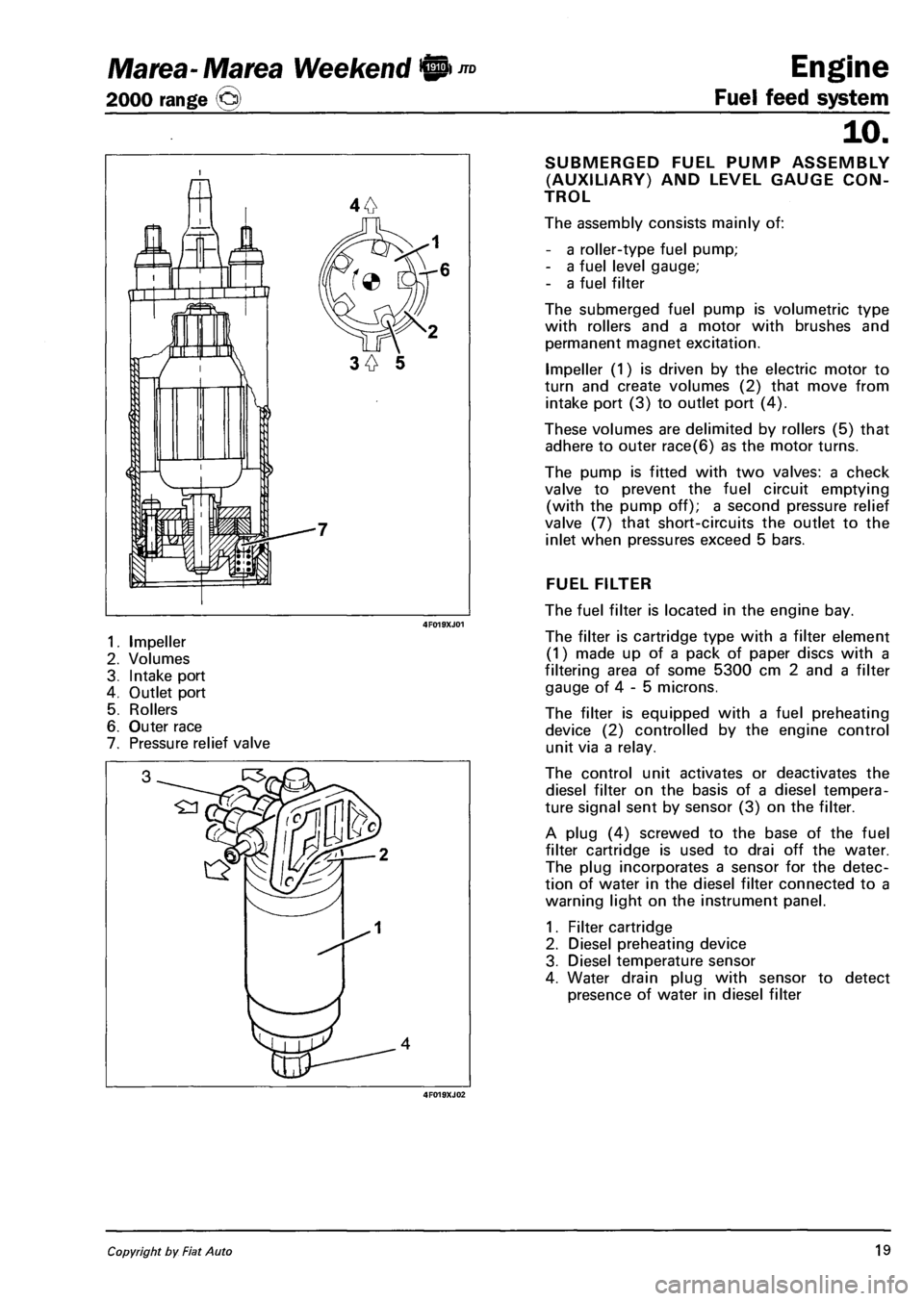
1. Impeller
2. Volumes
3. Intake port
4. Outlet port
5. Rollers
6. Outer race
7. Pressure relief valve
4F019XJ02
Engine
Fuel feed system
10.
SUBMERGED FUEL PUMP ASSEMBLY
(AUXILIARY) AND LEVEL GAUGE CON
TROL
The assembly consists mainly of:
- a roller-type fuel pump;
- a fuel level gauge;
- a fuel filter
The submerged fuel pump is volumetric type
with rollers and a motor with brushes and
permanent magnet excitation.
Impeller (1) is driven by the electric motor to
turn and create volumes (2) that move from
intake port (3) to outlet port (4).
These volumes are delimited by rollers (5) that
adhere to outer race(6) as the motor turns.
The pump is fitted with two valves: a check
valve to prevent the fuel circuit emptying
(with the pump off); a second pressure relief
valve (7) that short-circuits the outlet to the
inlet when pressures exceed 5 bars.
FUEL FILTER
The fuel filter is located in the engine bay.
The filter is cartridge type with a filter element
(1) made up of a pack of paper discs with a
filtering area of some 5300 cm 2 and a filter
gauge of 4 - 5 microns.
The filter is equipped with a fuel preheating
device (2) controlled by the engine control
unit via a relay.
The control unit activates or deactivates the
diesel filter on the basis of a diesel tempera
ture signal sent by sensor (3) on the filter.
A plug (4) screwed to the base of the fuel
filter cartridge is used to drai off the water.
The plug incorporates a sensor for the detec
tion of water in the diesel filter connected to a
warning light on the instrument panel.
1. Filter cartridge
2. Diesel preheating device
3. Diesel temperature sensor
4. Water drain plug with sensor to detect
presence of water in diesel filter
Copyright by Fiat Auto 19
Page 106 of 330
Engine
Fuel feed system
JTD Marea-Marea Weekend @
2000 range ©
10.
7^ £3
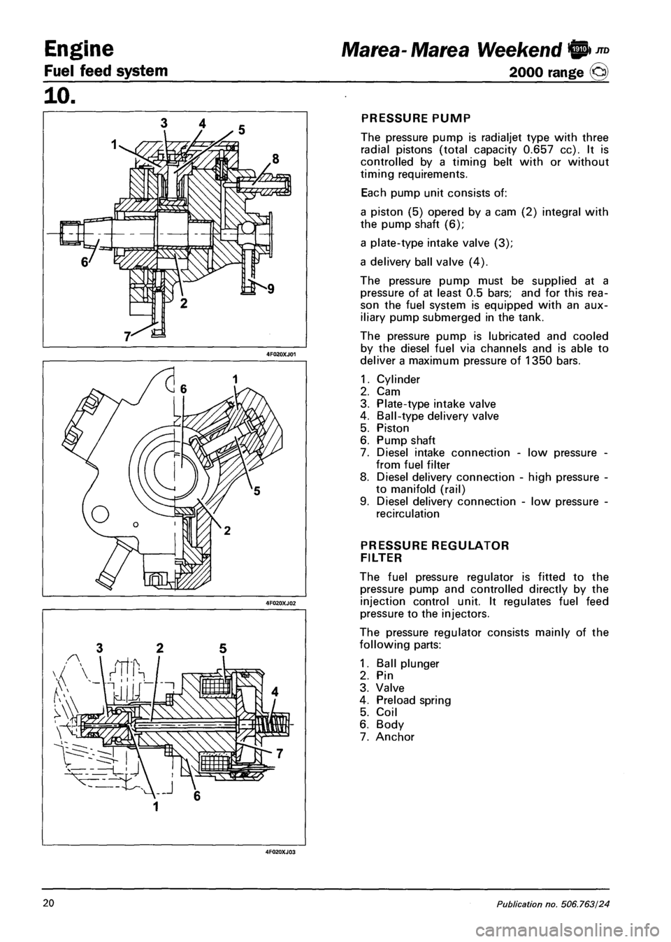
PRESSURE PUMP
The pressure pump is radialjet type with three
radial pistons (total capacity 0.657 cc). It is
controlled by a timing belt with or without
timing requirements.
Each pump unit consists of:
a piston (5) opered by a cam (2) integral with
the pump shaft (6);
a plate-type intake valve (3);
a delivery ball valve (4).
The pressure pump must be supplied at a
pressure of at least 0.5 bars; and for this rea
son the fuel system is equipped with an aux
iliary pump submerged in the tank.
The pressure pump is lubricated and cooled
by the diesel fuel via channels and is able to
deliver a maximum pressure of 1350 bars.
1.
2.
3.
4.
5.
6.
7.
8.
Cylinder
Cam
Plate-type intake valve
Ball-type delivery valve
Piston
Pump shaft
Diesel intake connection -
from fuel filter
Diesel delivery connection
to manifold (rail)
Diesel delivery connection
recirculation
low pressure
high pressure
low pressure
PRESSURE REGULATOR
FILTER
The fuel pressure regulator is fitted to the
pressure pump and controlled directly by the
injection control unit. It regulates fuel feed
pressure to the injectors.
The pressure regulator consists mainly of the
following parts:
1. Ball plunger
2. Pin
3. Valve
4. Preload spring
5. Coil
6. Body
7. Anchor
20 Publication no. 506.763/24
Page 107 of 330
Marea- Marea Weekend <§l ™
2000 range ©
Engine
Fuel feed system
TZZZZZZZZZZZZZZZZZZb
TZZZZZZZZZZZZZZ*
10.
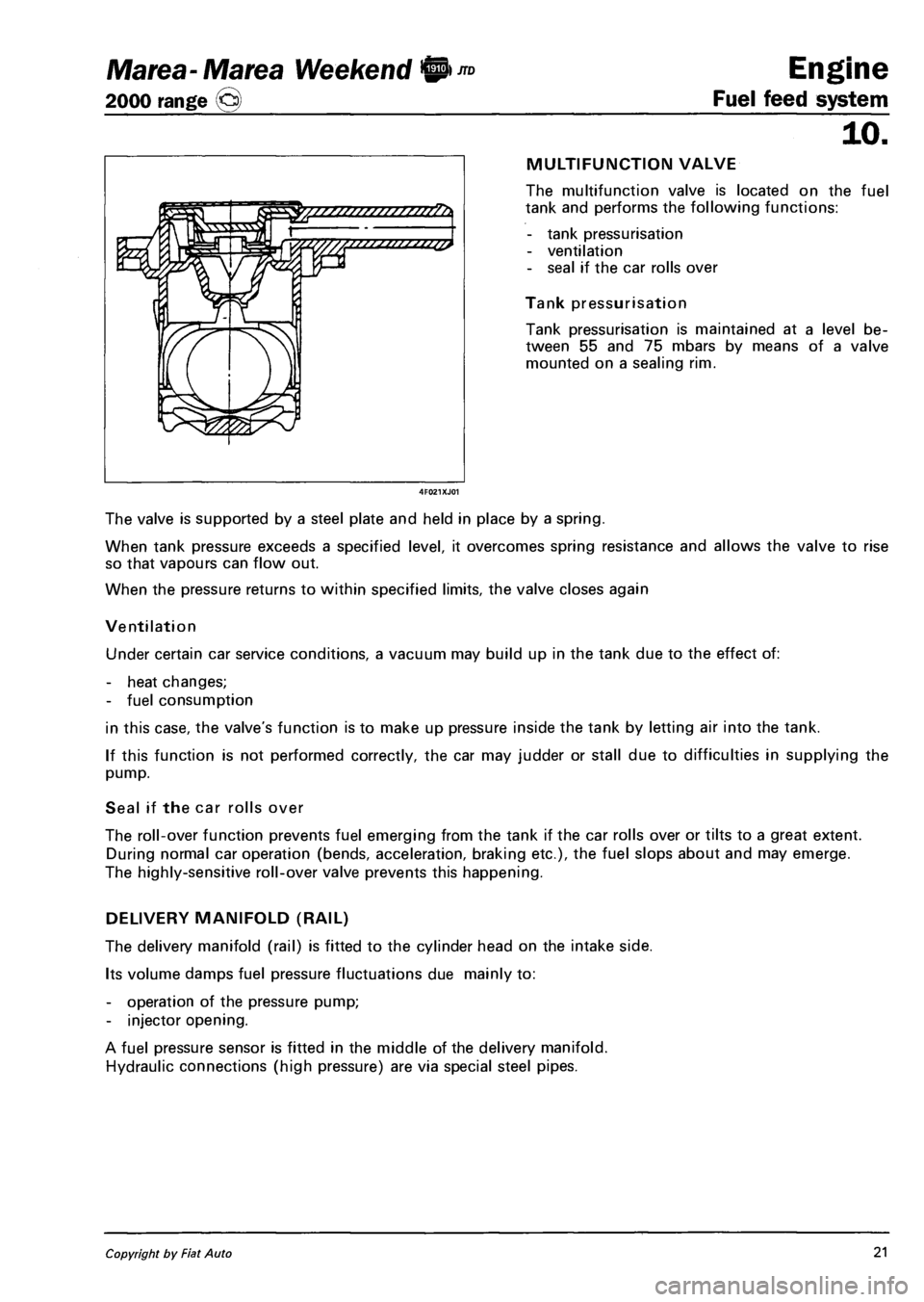
MULTIFUNCTION VALVE
The multifunction valve is located on the fuel
tank and performs the following functions:
- tank pressurisation
- ventilation
- seal if the car rolls over
Tank pressurisation
Tank pressurisation is maintained at a level be
tween 55 and 75 mbars by means of a valve
mounted on a sealing rim.
The valve is supported by a steel plate and held in place by a spring.
When tank pressure exceeds a specified level, it overcomes spring resistance and allows the valve to rise
so that vapours can flow out.
When the pressure returns to within specified limits, the valve closes again
Ventilation
Under certain car service conditions, a vacuum may build up in the tank due to the effect of:
- heat changes;
- fuel consumption
in this case, the valve's function is to make up pressure inside the tank by letting air into the tank.
If this function is not performed correctly, the car may judder or stall due to difficulties in supplying the
pump.
Seal if the car rolls over
The roll-over function prevents fuel emerging from the tank if the car rolls over or tilts to a great extent.
During normal car operation (bends, acceleration, braking etc.), the fuel slops about and may emerge.
The highly-sensitive roll-over valve prevents this happening.
DELIVERY MANIFOLD (RAIL)
The delivery manifold (rail) is fitted to the cylinder head on the intake side.
Its volume damps fuel pressure fluctuations due mainly to:
- operation of the pressure pump;
- injector opening.
A fuel pressure sensor is fitted in the middle of the delivery manifold.
Hydraulic connections (high pressure) are via special steel pipes.
Copyright by Fiat Auto 21
Page 226 of 330
Electrical equipment
Component location
Marea- Marea Weekend
2000 range ©
55.
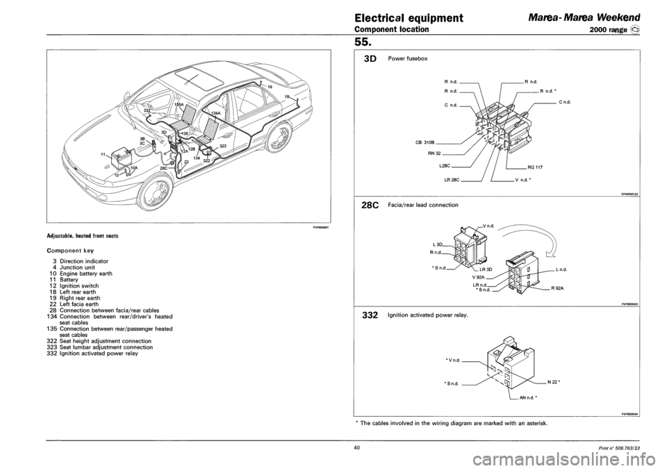
ADJUSTABLE, HEATED FRONT SEATS
Component key
3 Direction indicator
4 Junction unit
10 Engine battery earth
11 Battery
12 Ignition switch
18 Left rear earth
19 Right rear earth
22 Left facia earth
28 Connection between facia/rear cables
134 Connection between rear/driver's heated
seat cables
135 Connection between rear/passenger heated
seat cables
322 Seat height adjustment connection
323 Seat lumbar adjustment connection
332 Ignition activated power relay
3D Power fusebox
R n.d.
R n.d.
C n.d.
R n.d.
CB 31 OB .
RN 32.
L28C .
LR 28C
.R n.d.
Cn.d.
.RG 117
V n.d.
28C Facia/rear lead connection
_Vn.d
LRn.d *Sn.d
. Ln.d.
. R92A
332 Ignition activated power relay.
*Vn.d.
' S n.d. N22"
AN n.d.
P4F850N04
* The cables involved in the wiring diagram are marked with an asterisk.
40 Print n° 506.763/23
Page 319 of 330
Marea- Marea Weekend
2000 range ©
Electrical equipment
Connector blocks
55.
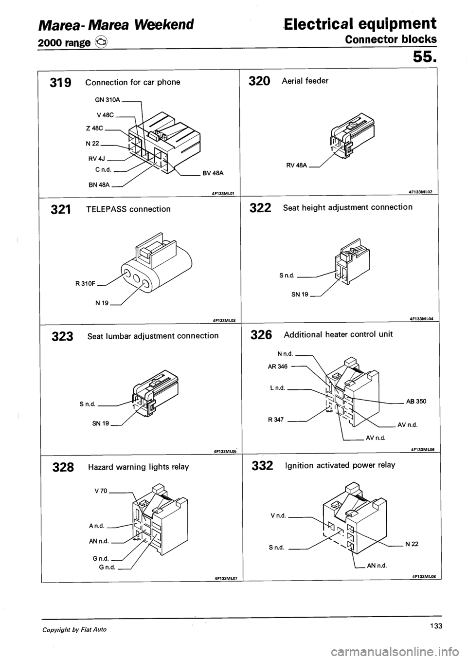
319 Connection for car phone
GN310A.
V48C.
Z48C.
N 22.
RV4J
BV48A
321 TELEPASS connection
R310F
320 Aerial feeder
RV48A
322 Seat height adjustment connection
N 19
323 Seat lumbar adjustment connection
Sn.d.
SN 19
328 Hazard warning lights relay
Sn.d.
SN 19
326 Additional heater control unit
AB350
R347 AV n.d.
332 Ignition activated power relay
Vn.d.
Sn.d. N22
AN n.d.
Copyright by Fiat Auto 133
Page 330 of 330
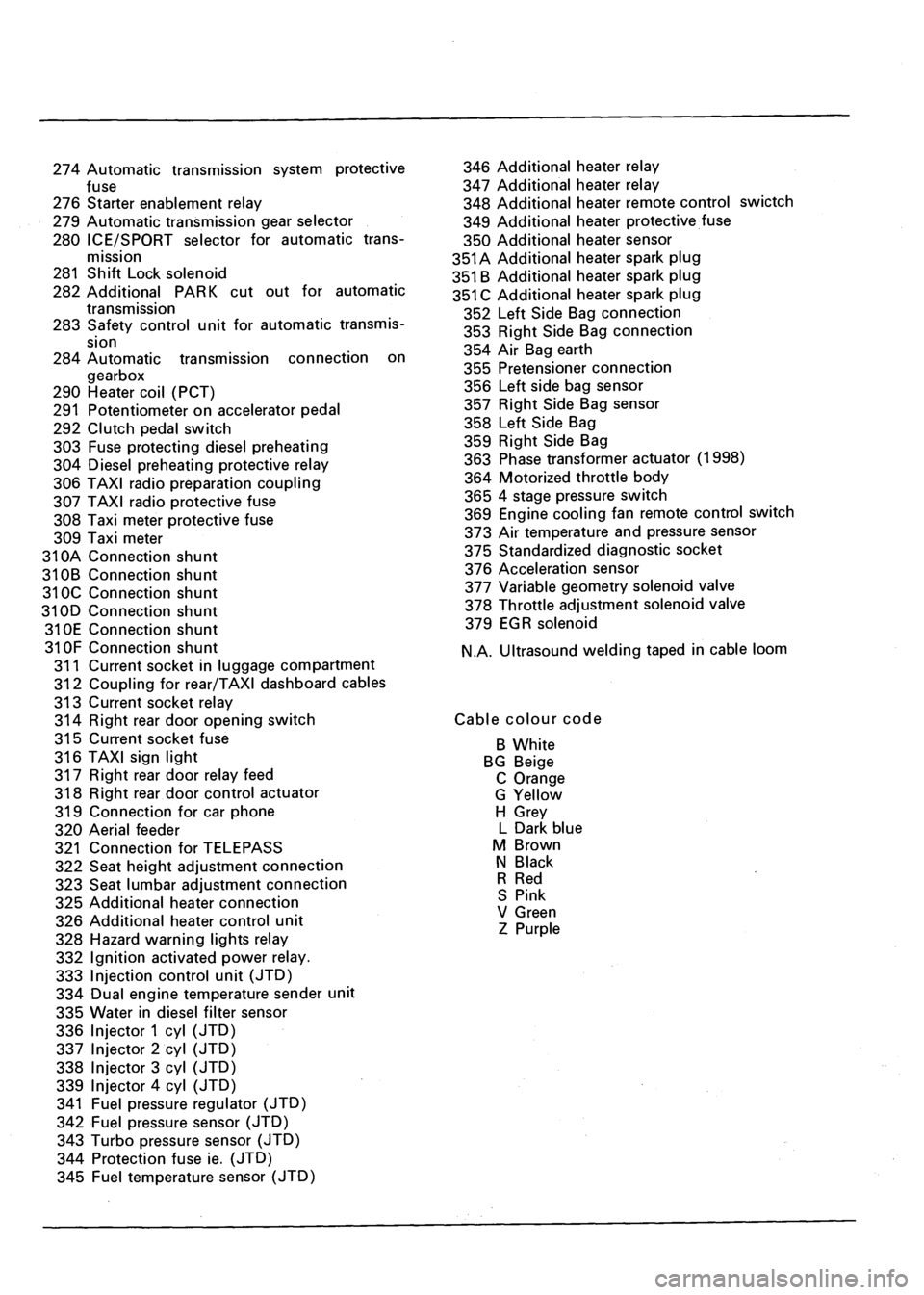
274 Automatic transmission system protective
fuse
276 Starter enablement relay
279 Automatic transmission gear selector
280 ICE/SPORT selector for automatic trans
mission
281 Shift Lock solenoid
282 Additional PARK cut out for automatic
transmission
283 Safety control unit for automatic transmis
sion
284 Automatic transmission connection on
gearbox
290 Heater coil (PCT)
291 Potentiometer on accelerator pedal
292 Clutch pedal switch
303 Fuse protecting diesel preheating
304 Diesel preheating protective relay
306 TAXI radio preparation coupling
307 TAXI radio protective fuse
308 Taxi meter protective fuse
309 Taxi meter
31 OA Connection shunt
310B Connection shunt
310C Connection shunt
310D Connection shunt
310E Connection shunt
31 OF Connection shunt
311 Current socket in luggage compartment
312 Coupling for rear/TAXI dashboard cables
313 Current socket relay
314 Right rear door opening switch
315 Current socket fuse
316 TAXI sign light
317 Right rear door relay feed
318 Right rear door control actuator
319 Connection for car phone
320 Aerial feeder
321 Connection for TELEPASS
322 Seat height adjustment connection
323 Seat lumbar adjustment connection
325 Additional heater connection
326 Additional heater control unit
328 Hazard warning lights relay
332 Ignition activated power relay.
333 Injection control unit (JTD)
334 Dual engine temperature sender unit
335 Water in diesel filter sensor
336 Injector 1 cyl (JTD)
337 Injector 2 cyl (JTD)
338 Injector 3 cyl (JTD)
339 Injector 4 cyl (JTD)
341 Fuel pressure regulator (JTD)
342 Fuel pressure sensor (JTD)
343 Turbo pressure sensor (JTD)
344 Protection fuse ie. (JTD)
345 Fuel temperature sensor (JTD)
346 Additional heater relay
347 Additional heater relay
348 Additional heater remote control swictch
349 Additional heater protective fuse
350 Additional heater sensor
351A Additional heater spark plug
351 B Additional heater spark plug
351 C Additional heater spark plug
352 Left Side Bag connection
353 Right Side Bag connection
354 Air Bag earth
355 Pretensioner connection
356 Left side bag sensor
357 Right Side Bag sensor
358 Left Side Bag
359 Right Side Bag
363 Phase transformer actuator (1998)
364 Motorized throttle body
365 4 stage pressure switch
369 Engine cooling fan remote control switch
373 Air temperature and pressure sensor
375 Standardized diagnostic socket
376 Acceleration sensor
377 Variable geometry solenoid valve
378 Throttle adjustment solenoid valve
379 EGR solenoid
N.A. Ultrasound welding taped in cable loom
Cable colour code
B White
BG Beige
C Orange
G Yellow
H Grey
L Dark blue
M Brown
N Black
R Red
S Pink
V Green
Z Purple