Dashboard FIAT MAREA 2001 1.G User Guide
[x] Cancel search | Manufacturer: FIAT, Model Year: 2001, Model line: MAREA, Model: FIAT MAREA 2001 1.GPages: 330
Page 216 of 330
4F030ML01
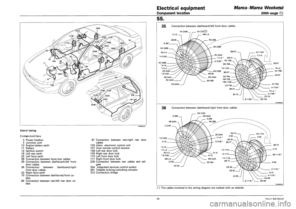
CENTRAL LOCKING
Component key
3 Power fusebox
4 Junction unit:
10 Engine battery earth
11 Battery
12 Ignition switch
18 Left rear earth
22 Left facia earth
28 Connection between facia/rear cables
35 Connection between dashboard/left front
door cables
36 Connection between dashboard/right
front door cables
42 Right facia earth
70 Connection between dashborad/front ca
bles
86 Connection between rear/left rear door ca
bles
87 Connection between rear/right rear door
cables
100 Alarm electronic control unit
107 Door remote control receiver
108 Left rear door lock
109 Right rear door lock
110 Left front door lock
111 Right front door lock
236 Connection between rear cables and tail
gate
244 Integrated services control system
261 Tailgate locking/unlocking actuator
310 Connection bridge
Electrical equipment Marea-Marea Weekend
Component location 2000 range ©
55.
35 Connection between dashboard/left front door cables
36 Connection between dashboard/right front door cables
P4F830N03
(*) The cables involved in the wiring diagram are marked with an asterisk.
30 Print n° 506.763/23
Page 218 of 330
Electrical equipment
Component location
Marea-Marea Weekend
2000 range ©
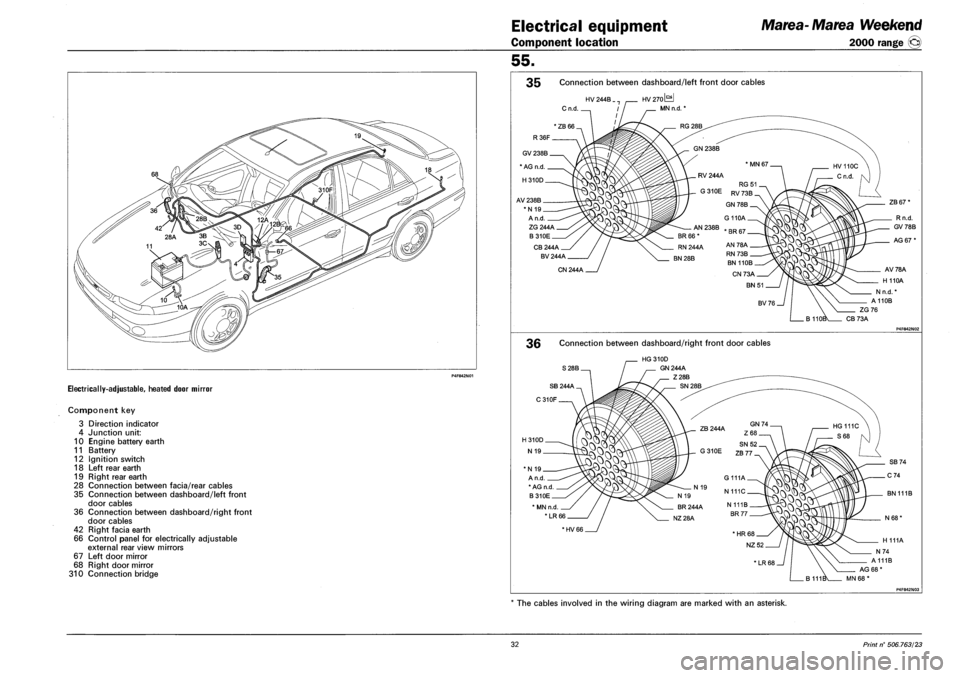
ELECTRICALLY-ADJUSTABLE, HEATED DOOR MIRROR
Component key
3 Direction indicator
4 Junction unit:
10 Engine battery earth
11 Battery
12 Ignition switch
18 Left rear earth
19 Right rear earth
28 Connection between facia/rear cables
35 Connection between dashboard/left front
door cables
36 Connection between dashboard/right front
door cables
42 Right facia earth
66 Control panel for electrically adjustable
external rear view mirrors
67 Left door mirror
68 Right door mirror
310 Connection bridge
55.
35 Connection between dashboard/left front door cables
HV 244B ..
Cn.d. .
HV270L^J
MN n.d. *
ZG 244A
B310E
CB244A
BV 244A
CN 244A
ZB 67'
Rn.d.
GV 78 B
AG 67*
AV78A
H 110A
Nn.d.'
A110B
ZG76
CB73A
36 Connection between dashboard/right front door cables
S28B.
HG 310D
GN 244A
Z28B
*N 19
A n.d
* AG n.d
B310E
* MN n.d
*LR66
BN 111B
*HV 66
The cables involved in the wiring diagram are marked with an asterisk.
32 Print n° 506.763/23
Page 230 of 330
Electrical equipment
Component location
Marea- Marea Weekend
2000 range ©
55.
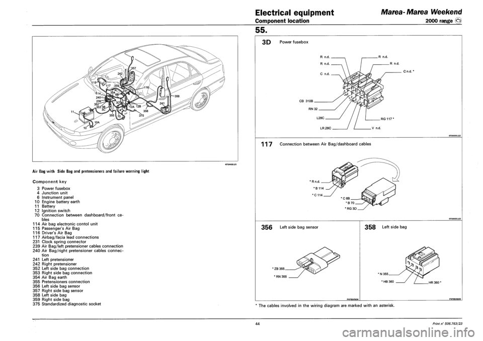
AIR BAG WITH SIDE BAG AND PRETENSIONERS AND FAILURE WARNING LIGHT
Component key
3 Power fusebox
4 Junction unit
6 Instrument panel
10 Engine battery earth
11 Battery
12 Ignition switch
70 Connection between dashboard/front ca
bles
114 Air bag electronic contol unit
115 Passenger's Air Bag
116 Driver's Air Bag
117 Airbag/facia lead connections
231 Clock spring connector
239 Air Bag/left pretensioner cables connection
240 Air Bag/right pretensioner cables connec
tion
241 Left pretensioner
242 Right pretensioner
352 Left side bag connection
353 Right side bag connection
354 Air Bag earth
355 Pretensioners connection
356 Left side bag sensor
357 Right side bag sensor
358 Left side bag
359 Right side bag
375 Standardized diagnostic socket
3D Power fusebox
R n.d.
R n.d.
Cn.d.*
RG 117'
LR 28C V n.d.
117 Connection between Air Bag/dashboard cables
* RG 3D
356 Left side bag sensor
' ZB 355
' RN 355
358 Left side bag
HR 360'
The cables involved in the wiring diagram are marked with an asterisk.
44 Print n° 506.763/23
Page 238 of 330
Electrical equipment
Component location
Marea- Marea Weekend
2000 range ®
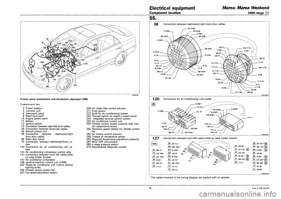
Climate control system/heater with thermostatic adjustment (1596)
Component key
3 Power fusebox
4 Junction unit
6 Instrument panel
9 Right front earth
10 Engine battery earth
11 Battery
12 Ignition switch
13 Connection between right/left front cables
28 Connection between facia/rear cables
34 Switch control unit
36 Connection between dashboard/right
front door cables
68 Right door mirror
70 Connection between dashborad/front ca
bles
120 Connection for air conditioning unit ca
bles
124 Air condiitoning compressor control relay
127 Connection between front left cable/cable
on relay holder bracket
147 Air conditioner compressor
195 Ignition/injection control unit (1596)
202 Heater/air conditioner unit control symbol
lighting bulbs
206 Climate control system fan
207 Fan speed adjustment switch
209 Air intake flap control actuator
211 Frost sensor
222 Earth for air conditioning system
233 Thermal switch on engine coolant pump
244 Integrated services control system
253 Air conditioner control unit
254 Climate control system controls with inte
rior temperature sensor
255 Electronic speed variator for climate control
fan
256 Air mixing control actuator
258 Treated air temperature sensor
259 Required temperature adjustment solenoid
260 MAX-DEF microswitch
365 4-stage pressure switch
375 Standardized diagnostic socket
55.
36 Connection between dashboard/right front door cables
* S 28B.
HG310D
GN 244A
Z28B
N 19 _
A n.d.
AG n.d
B310E
MN n.d.
LR66
BN 111B
HV66
AG 68
MN 68
1 20 Connection for air conditioning unit cables
1Z 28B.
*N22.
"AN 70
' RN 70.
. Z n.d.
127
1596
Connection between front left cable/cable on relay holder bracket
62 AN n.d. *
B3 MG 195A*
A2 RN 13 B4 S195A*
A4 AB 195A B5 VN3A
A5 AG 195A B6 B195A
A6 M3A* B7 VG70*
A7 MN 13* C2 BN 195A
A8 Cn.d. C3 HL n.d.
C4 SG n.d.
RN 98
_AlAV123 g*]
A5 AG 122
_A6_ M 124 * [§]
JiL MN 124 *[§]
_*!L C n.d.
_§?_ AN 124*[§]
_B3_MG 124 *§]
-US 365* [$]
J*!LVN98
J?6. B 365 [ffi
_g7_ VG 365*[
_Pi_ HL98
_?i_SG 98
The cables involved in the wiring diagram are marked with an asterisk.
52 Print n° 506.763/23
Page 240 of 330
Electrical equipment
Component location
Marea- Marea Weekend
2000 range ®
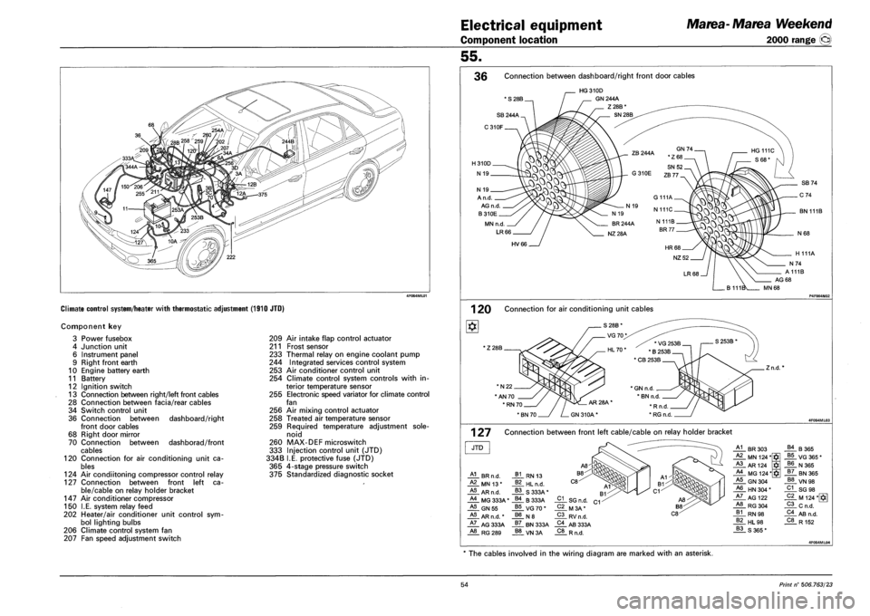
Climate control system/heater with thermostatic adjustment (1910 JTO)
Component key
Power fusebox
Junction unit
Instrument panel
Right front earth
Engine battery earth
Battery
Ignition switch
Connection between right/left front cables
Connection between facia/rear cables
Switch control unit
Connection between
front door cables
Right door mirror
Connection between
cables
Connection for air conditioning unit ca
bles
124 Air condiitoning compressor control relay
127 Connection between front left ca
ble/cable on relay holder bracket
Air conditioner compressor
I.E. system relay feed
Heater/air conditioner unit control sym
bol lighting bulbs
Climate control system fan
Fan speed adjustment switch
3
4
6
9
10
11
12
13
28
34
36
68
70
120
147
150
202
206
207
dashboard/right
dashborad/front
209 Air intake flap control actuator
211 Frost sensor
233 Thermal relay on engine coolant pump
244 Integrated services control system
253 Air conditioner control unit
254 Climate control system controls with in
terior temperature sensor
255 Electronic speed variator for climate control
fan
256 Air mixing control actuator
258 Treated air temperature sensor
259 Required temperature adjustment sole
noid
260 MAX-DEF microswitch
333 Injection control unit (JTD)
334B I.E. protective fuse (JTD)
365 4-stage pressure switch
375 Standardized diagnostic socket
55.
36 Connection between dashboard/right front door cables
' S 28B.
HG310D
GN 244A
Z28B*
SN 28B
A n.d.
AG n.d.
B310E
MN n.d
LR66
BN 111B
HV66
1 20 Connection for air conditioning unit cables
' Z 28B
*N22.
"AN 70
.Zn.d.
1 27 Connection between front left cable/cable on relay holder bracket
JTD
HL BR n.d.
_ALMNI3*
HL AR n.d.
HL MG 333A'
HL GN55
HL AR n.d. *
HL AG 333A A8 RG289
_A1_ BR 303 B4 B365 A2 MN 124* $ B5 VG 365 * A3 AR124 B6 N365 A4 MG 124* $ B7 BN 365 A5 GN 304 B8 VN 98 A6 HN 304 * C1 SG 98 A7 AG 122 C2 M 124*[*g A8 RG304 C3 Cn.d. B1 RN 98 C4 AB n.d. B2 HL 98 C8 R152 B3 S365*
The cables involved in the wiring diagram are marked with an asterisk.
54 Print n° 506.763/23
Page 242 of 330
![FIAT MAREA 2001 1.G User Guide Electrical equipment
Component location
Marea- Marea Weekend
2000 range ©
Climate control unit/heater with thermostatic control (1998)
Component key
] 3 Power fusebox
4 Junction unit
6 Instru FIAT MAREA 2001 1.G User Guide Electrical equipment
Component location
Marea- Marea Weekend
2000 range ©
Climate control unit/heater with thermostatic control (1998)
Component key
] 3 Power fusebox
4 Junction unit
6 Instru](/img/10/4653/w960_4653-241.png)
Electrical equipment
Component location
Marea- Marea Weekend
2000 range ©
Climate control unit/heater with thermostatic control (1998)
Component key
] 3 Power fusebox
4 Junction unit
6 Instrument panel
10 Engine battery earth
11 Battery
12 Ignition switch
28 Connection between facia/rear cables
34 Switch control unit
36 Connection between dashboard/right
front door cables
55 Connection between front/engine cables
68 Right door mirror
70 Connection between dashborad/front ca
bles
120 Connection for air conditioning unit ca
bles
124 Air condiitoning compressor control relay
127 Connection between front left cable/cable
on relay holder bracket
147 Air conditioner compressor
190 Injection/ignition electronic control unit
(1998)
202 Heater/air conditioner unit control symbol
lighting bulbs
206 Climate control system fan
207 Fan speed adjustment selector
209 Air intake flap control actuator
211 Frost sensor
222 Earth for air conditioning system
244 Integrated services control system
253 Air conditioner control unit
254 Climate control system controls with inte
rior temperature sensor
255 Electronic speed variator for climate control
fan
256 Air mixing control actuator
258 Treated air temperature sensor
259 Required temperature adjustment solenoid
260 MAX-DEF microswitch
365 4-stage pressure switch
375 Standardized diagnostic socket
55.
36 Connection between dashboard/right front door cables
* S 28B.
HG 310D
GN 244A
Z28B
N 19.
A n.d.
AG n.d.
B310E.
MN n.d
LR66
BN 111B
HV66
1 20 Connection for air conditioning unit cables
* Z 28B.
*N22.
'AN 70 _
*RN70
'BN 70
AR28A
GN310A*
. Zn.d.
1 27 Connection between front left cable/cable on relay holder bracket
1998
A1 Rn.d. B1 MB 4C A2 RN 13 B2 AN n.d. * A3 BG 190A B3 MG 190A* A4 AB 190A B4 S190A* A5 AG 190A B5 VN3A A6 M3A* B6 B 190A A7 MN 55* B7 VG70* A8 Cn.d. B8 Rn.d.
C2
C3
C4
C5
C6
C7
BN190A B1
HLn.d. C1
SG n.d.
HRn.d.
AR n.d.
G 190A
A1 Rn.d. B4 S365* 0 A2 RN 98 B5 VN 98 A3 BV151 B6 B365 A4 AB123 @ VG 365' A5 AG 122 @ B8 R 150 A6 M 124* C2 BN 365 A7 MN 124* C3 HL98 A8 Cn.d. C4 SG98 B1 MB 151 C5 HR 152A B2 AN 124 * C6 AR152B B3 MG 124* C7 G 150
The cables involved in the wiring diagram are marked with an asterisk.
56 Print n° 506.763/23
Page 262 of 330
Electrical equipment
Component location
Marea-Marea Weekend
2000 range ©
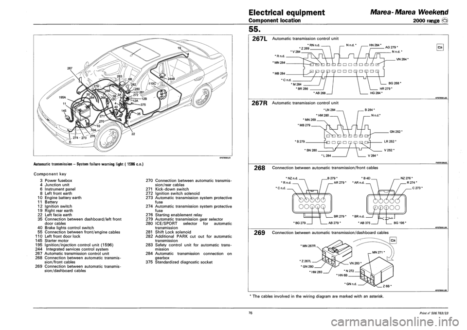
Automatic transmission - System failure warning light ( 1596 c.a.)
Component key
3 Power fusebox
4 Junction unit
6 Instrument panel
8 Left front earth
10 Engine battery earth
11 Battery
12 Ignition switch
19 Right rear earth
22 Left facia earth
35 Connection between dashboard/left front
door cables
40 Brake lights control switch
55 Connection between front/engine cables
110 Left front door lock
145 Starter motor
195 Ignition/injection control unit (1596)
244 Integrated services control system
267 Automatic transmission control unit
268 Connection between automatic transmis
sion/front cables
269 Connection between automatic transmis
sion/dashboard cables
270 Connection between automatic transmis
sion/rear cables
271 Kick-down switch
272 Ignition switch solenoid
273 Automatic transmission system protective
fuse
274 Automatic transmission system protective
fuse
276 Starting enablement relay
279 Automatic transmission gear selector
280 ICE/SPORT selector for automatic
transmission
281 Shift Lock solenoid
282 Additional PARK cut out for automatic
transmission
283 Safety control unit for automatic trans
mission
284 Automatic transmission connection on
gearbox
375 Standardized diagnostic socket
55.
267L Automatic transmission control unit
*RNn.d , . Nn.d.' HN 284 * *Z269 'V284
AG 279 *
N n.d.'
OS
VN 284*
* MB 284
* C n.d.
M284
• BR 286
BG 268'
HR 279 *
* AB 268 HG 284 *
267R Automatic transmission control unit
* LN 284
' HM 280
* MN 269
' MB 279
* S 279.
GN 252'
* SN 280.
L284 / \ V284*
LR 252 *
V252*
268 Connection between automatic transmission/front cables
B 279 *
AR 279 *
*B4D NZ 276 *
• AR n.d
' BG 279 AB 279 * BG 195'
269 Connection between automatic transmission/dashboard cables
' MN 267R
The cables involved in the wiring diagram are marked with an asterisk.
76 Print n° 506.763/23
Page 264 of 330
Electrical equipment
Component location
Marea-Matea Weekend
2000 range ©
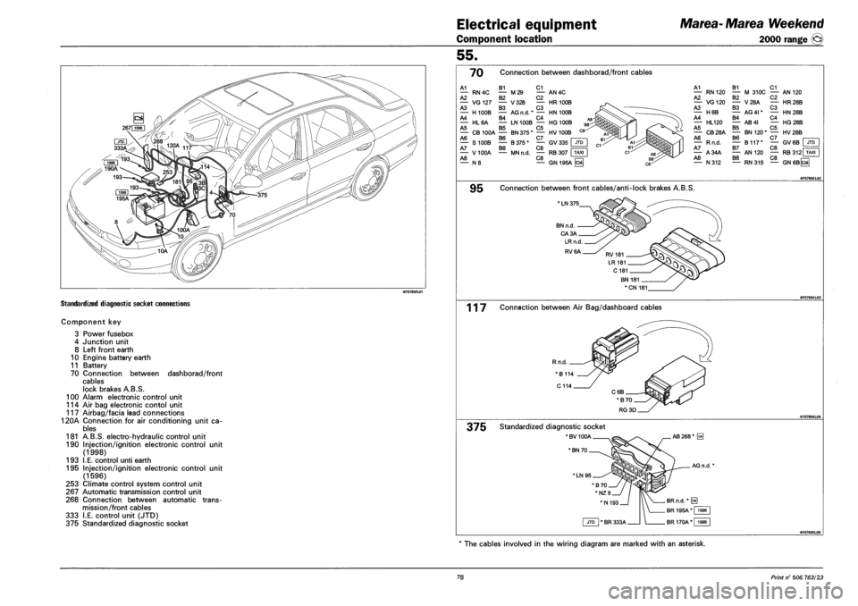
STANDARDIZED DIAGNOSTIC SOCKET CONNECTIONS
COMPONENT KEY
3
4
8
10
11
70
100
114
117
120A
181
190
193
195
253
267
268
333
375
Power fusebox
Junction unit
Left front earth
Engine battery earth
Battery
Connection between dashborad/front
cables
lock brakes A.B.S.
Alarm electronic control unit
Air bag electronic contol unit
Airbag/facia lead connections
Connection for air conditioning unit ca
bles
A.B.S. electro-hydraulic control unit
Injection/ignition electronic control
(1998)
I.E. control unti earth
Injection/ignition electronic control
(1596)
Climate control system control unit
Automatic transmission control unit
Connection between automatic trans
mission/front cables
I.E. control unit (JTD)
Standardized diagnostic socket
unit
unit
55.
70 Connection between dashborad/front cables
A1
A2 RN4C B1 C1 — M29 — AN4C B2 C2 — HR100B C3 AG n.d.* — HN 100B B4 C4 — LN100B — HG100B B5 C5 — CB100A — BN375* — HV 100B A6 B6 C7 — S100B — B375* — GV335 A7 B8 C8 — V100A — MNn.d. — RB 307 A8 C8 — N 8 — GN 195A
— VG 127 — V 328 A3 B3 — H100B — A4 — HL6A A5
A1 — RN120 A2 — VG120 A3 — H6B A4 — HL120 A5 — CB28A A6 — Rn.d. A7 — A34A A8 — N312
B1 C1 — M 310C — AN 120 B2 — V28A B3 — AG4I* B4 — AB4I B5 — BN120" B6 — B117* B7 — AN 120 B8 — RN315
C2 — HR28B C3 — HN28B C4 — HG28B C5 — HV28B C7 I — GV6B | JTD C8 — RB 312 TAXI C8 —I — GN6BQ
9B Connection between front cables/anti-lock brakes A.B.S.
* LN 375
BN n.d
CA3A
*CN 181
117 Connection between Air Bag/dashboard cables
Rn.d.
375 Standardized diagnostic socket
*BV100A
* BN 70
'LN95
The cables involved in the wiring diagram are marked with an asterisk.
78 Print n° 506.763/23
Page 266 of 330
Electrical equipment
Component location
Marea-Marea Weekend
2000 range ©
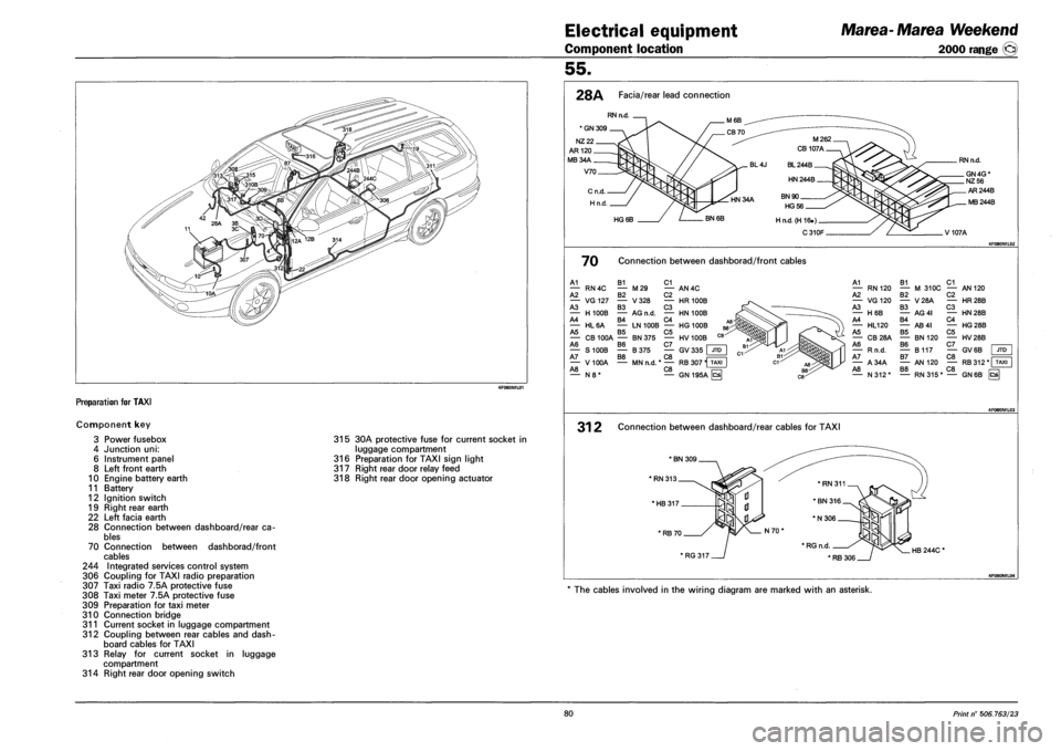
Preparation for TAXI
Component key
3 Power fusebox
4 Junction uni:
6 Instrument panel
8 Left front earth
10 Engine battery earth
11 Battery
12 Ignition switch
19 Right rear earth
22 Left facia earth
28 Connection between dashboard/rear ca
bles
70 Connection between dashborad/front
cables
244 Integrated services control system
306 Coupling for TAXI radio preparation
307 Taxi radio 7.5A protective fuse
308 Taxi meter 7.5A protective fuse
309 Preparation for taxi meter
310 Connection bridge
311 Current socket in luggage compartment
312 Coupling between rear cables and dash
board cables for TAXI
313 Relay for current socket in luggage
compartment
314 Right rear door opening switch
315 30A protective fuse for current socket in
luggage compartment
316 Preparation for TAXI sign light
317 Right rear door relay feed
318 Right rear door opening actuator
55.
28A Facia/rear lead connection
RN n.d.
' GN 309 .
NZ 22.
AR 120 _
MB34A.
V70.
M262
CB 107A
BL 244B.
HN 244B.
. HN 34A BN 90 _
HG56.
HG 6B BN 6B H n.d.(H 16.) _
C310F
RN n.d.
_ GN 4G * _NZ 56
AR244B
. MB 244B
V107A
70 Connection between dashborad/front cables
A1 B1 C1 — RN4C — M29 — AN4C A2 B2 C2 — VG127 — V328 — HR 100B A3 B3 C3 — H100B — AG n.d. — HN 100B A4 B4 C4 — HL6A — LN100B — HG 100B A5 B5 C5 — CB100A — BN375 — HV100B A6 B6 C7 — S100B — B375 — GV335 JTD A7 B8 C8 — V100A — MNn.d. *— RB 307 H TAXI A8 C8 n=n — N8* — GN195A ^
A1 B1 C1 — RN 120 — M 310C — AN 120 A2 B2 C2 — VG120 — V28A — HR28B A3 B3 C3 — H6B — AG4I — HN28B A4 B4 C4 — HL120 — AB4I — HG28B A5 B5 C5 — CB28A — BN120 — HV28B A6 B6 C7 — Rn.d. — B117 — GV6B A7 B7 C8 — A34A — AN 120 — RB312* T A8 B8 C8 — N312* — RN315* — GN 6B hs
JTD
31 2 Connection between dashboard/rear cables for TAXI
'HB317.
* RB 70.
' RG 317 HB 244C *
4F080ML04
The cables involved in the wiring diagram are marked with an asterisk.
80 Print n° 506.763/23
Page 279 of 330
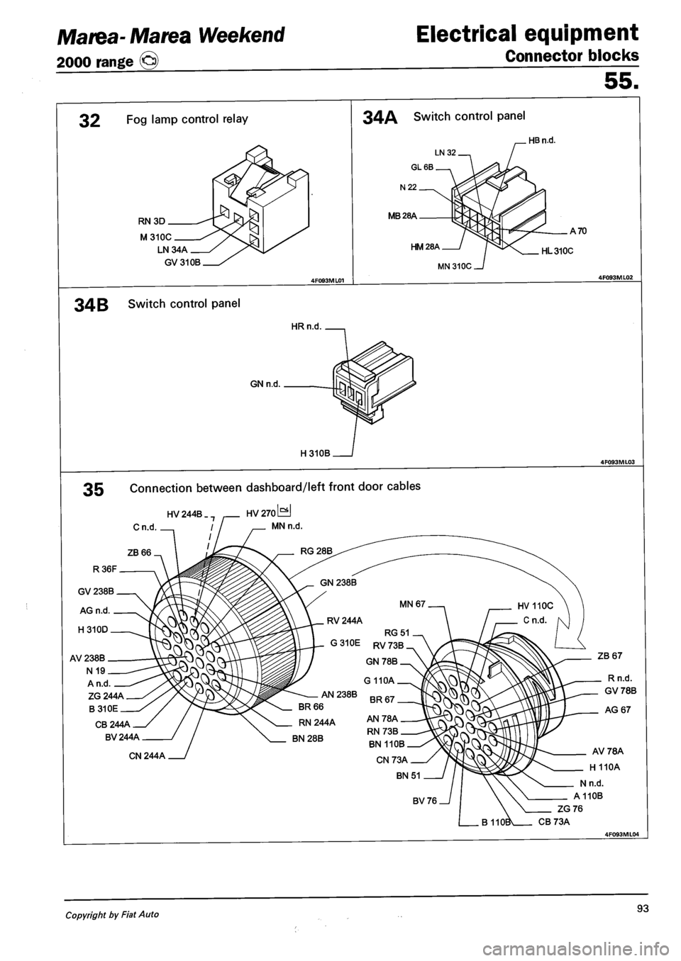
Marea- Marea Weekend
2000 range ©
Electrical equipment
Connector blocks
55.
32 Fog lamp control relay
RN 3D
M310C
LN34A
GV310B
34A Switch control panel
MB28A
HM28A
34 B Switch control panel
HRn.d
GN n.d.
H310B
. HB n.d.
A 70
HL 310C
35 Connection between dashboard/left front door cables
HV 244B
Cn.d
HV 270 iHJ
MN n.d.
ZG 244A
B310E
CB 244A
BV 244A
CN 244A
ZB 67
Rn.d.
GV 78B
AG 67
AV78A
H 110A
Nn.d.
A110B
ZG76
CB 73A
Copyright by Fiat Auto 93