comp FIAT MAREA 2001 1.G User Guide
[x] Cancel search | Manufacturer: FIAT, Model Year: 2001, Model line: MAREA, Model: FIAT MAREA 2001 1.GPages: 330
Page 28 of 330
Marea- Marea Weekend Technical Data
2000 range (Q) Engine: cylinder head and valve gear components
OO.io
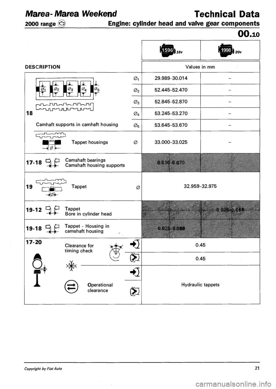
DESCRIPTION
16v 20v
Values in mm
r-jn_J_jnjT_^jnJ-^JTjnr^-JTJ-|
L-f,-n_rij^-T_n_rLj-,-jijtj_^^
0i 29.989-30.014
02 52.445-52.470
03 52.845-52.870
04 53.245-53.270
Camhaft supports in camhaft housing 05 53.645-53.670
n—,—nnTL
•QM Tappet housings 0 33.000-33.025
17-18 ^ P Camshaft bearings
»| |< Camshaft housing supports 0.030-0.070
19
—-^_J~l— r-u—u~~l_ —LJ—^—LJ-i-a_r>—1-1
OHO Tappet 0 32.959-32.975
19-12 ^ P Tappet
H H Bore in cyli cylinder head
19-18 ^ P Tappet - Housing in ,5'"10 »| |< camshaft housing 0.02S-0.066
0.025-0,066
17-20 Clearance for
timing check HQ 0.45
® 0.45
1
HQ
Operational
clearance ®
Hydraulic tappets
Copyright by Fiat Auto 21
Page 29 of 330
Technical Data Marea- Marea Weekend
Engine: cylinder head and valve gear components 2000 range @)
OO.io
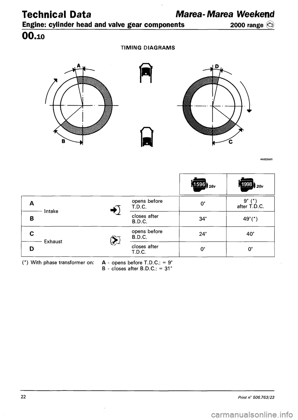
TIMING DIAGRAMS
A
HQ
opens before
T.D.C. 0° 9° (*) after T.D.C.
imaKe
B
HQ closes after
B.D.C. 34° 49°(*)
C
®
opens before
B.D.C. 24° 40°
CXnaUSl
D
® closes after
T.D.C. 0° 0°
(*) With phase transformer on: A - opens before T.D.C: = 9°
B - closes after B.D.C: = 31°
22 Print n° 506.763/23
Page 34 of 330
Marea-Marea Weekend Technical Data
2000 range (j§) Engine: fuel system - special tools
OO.io
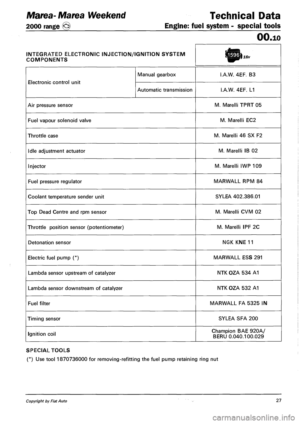
INTEGRATED ELECTRONIC INJECTION/IGNITION SYSTEM
COMPONENTS
Electronic control unit
Manual gearbox I.A.W. 4EF. B3
Electronic control unit
Automatic transmission I.A.W. 4EF. L1
Air pressure sensor M. Marelli TPRT 05
Fuel vapour solenoid valve M. Marelli EC2
Throttle case M. Marelli 46 SX F2
Idle adjustment actuator M. Marelli IB 02
Injector M. Marelli IWP 109
Fuel pressure regulator MARWALL RPM 84
Coolant temperature sender unit SYLEA 402.386.01
Top Dead Centre and rpm sensor M. Marelli CVM 02
Throttle position sensor (potentiometer) M. Marelli IPF 2C
Detonation sensor NGK KNE 11
Electric fuel pump (*) MARWALL ESS 291
Lambda sensor upstream of catalyzer NTK OZA 534 A1
Lambda sensor downstream of catalyzer NTK OZA 532 A1
Fuel filter MARWALL FA 5325 IN
Timing sensor SYLEA SFA 200
Ignition coil Champion BAE 920A/
BERU 0.040.100.029
SPECIAL TOOLS
(*) Use tool 1870736000 for removing-refitting the fuel pump retaining ring nut
Copyright by Fiat Auto 27
Page 35 of 330
Technical Data Marea- Marea Weekend
Engine: fuel system - special tools 2000 arnge ©)
OO.io
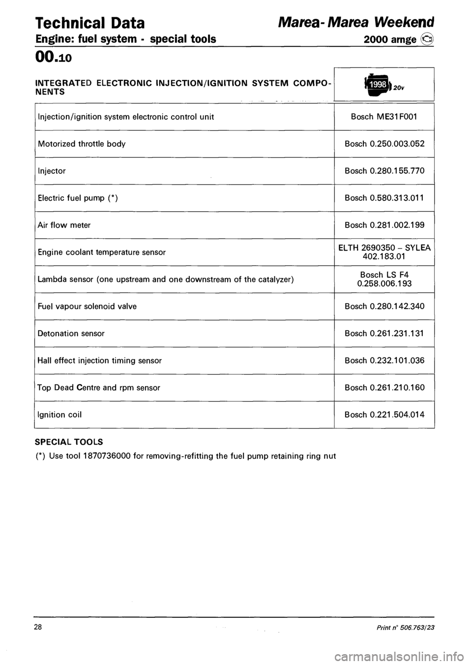
INTEGRATED ELECTRONIC INJECTION/IGNITION SYSTEM COMPO
NENTS
Injection/ignition system electronic control unit Bosch ME31F001
Motorized throttle body Bosch 0.250.003.052
Injector Bosch 0.280.155.770
Electric fuel pump (*) Bosch 0.580.313.011
Air flow meter Bosch 0.281.002.199
Engine coolant temperature sensor ELTH 2690350 - SYLEA
402.183.01
Lambda sensor (one upstream and one downstream of the catalyzer) Bosch LS F4
0.258.006.193
Fuel vapour solenoid valve Bosch 0.280.142.340
Detonation sensor Bosch 0.261.231.131
Hall effect injection timing sensor Bosch 0.232.101.036
Top Dead Centre and rpm sensor Bosch 0.261.210.160
Ignition coil Bosch 0.221.504.014
SPECIAL TOOLS
(*) Use tool 1870736000 for removing-refitting the fuel pump retaining ring nut
28 Print n° 506.763/23
Page 36 of 330
Marea-Marea Weekend
2000 range ©
Technical Data
Engine
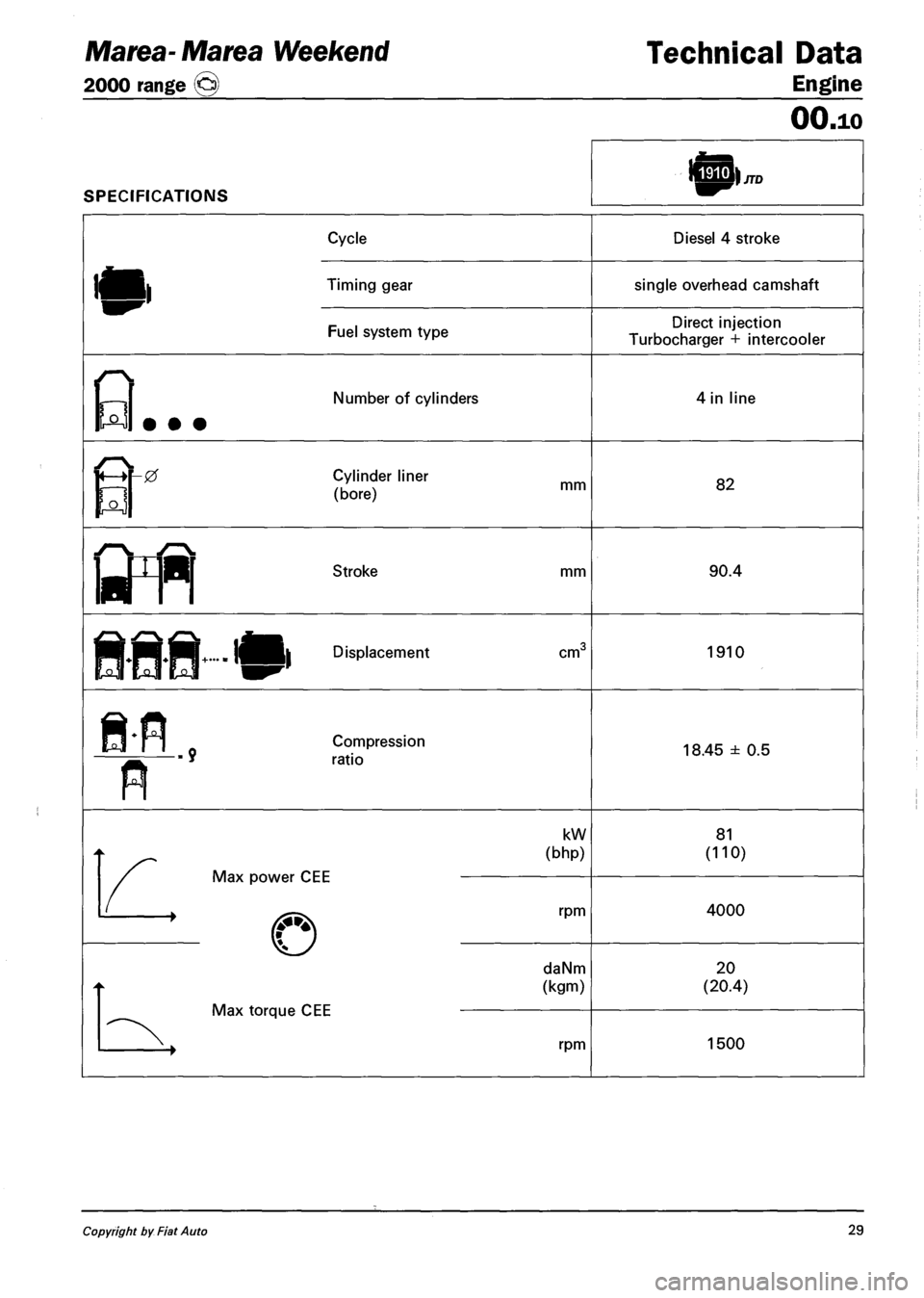
SPECIFICATIONS
OO.io
JTD
Cycle
Timing gear
Fuel system type
Diesel 4 stroke
single overhead camshaft
Direct injection
Turbocharger + intercooler
Number of cylinders 4 in line
r
0 Cylinder liner
(bore) mm 82
Stroke mm 90.4
Displacement cm 1910
Compression
ratio 18.45 ± 0.5
kW
(bhp)
Max power CEE
rpm
daNm
(kgm)
Max torque CEE
rpm
81
(110)
4000
20
(20.4)
1500
Copyright by Fiat Auto 29
Page 37 of 330
Technical Data Marea- Marea Weekend
Engine: cylinder head and valve gear components 2000 range (§)
OO.io
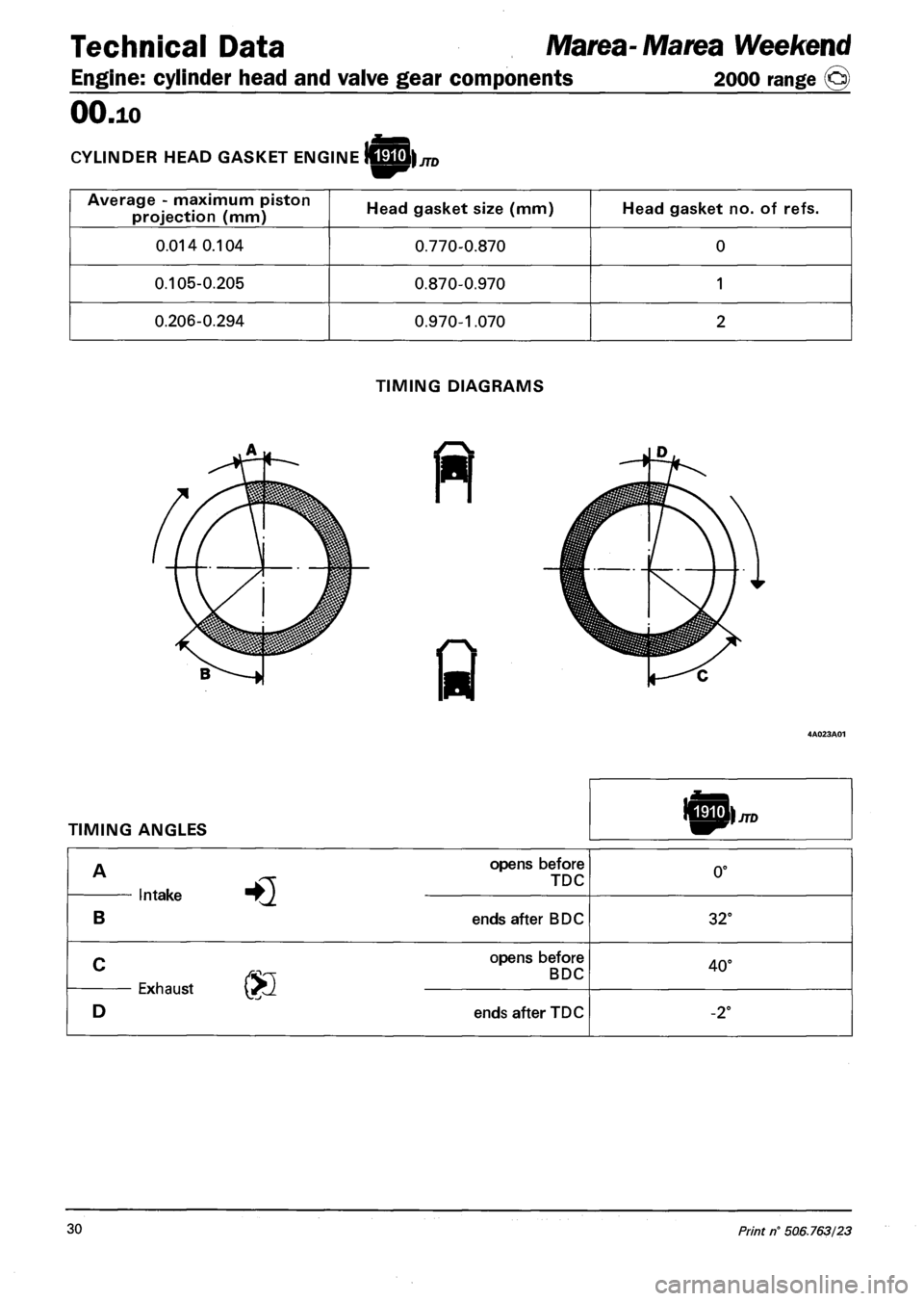
CYLINDER HEAD GASKET ENGINE ||£k JTD
Average - maximum piston
projection (mm) Head gasket size (mm) Head gasket no. of refs.
0.014 0.104 0.770-0.870 0
0.105-0.205 0.870-0.970 1
0.206-0.294 0.970-1.070 2
TIMING DIAGRAMS
ft
TIMING ANGLES JTD
Intake
B
opens before
TDC
ends after BDC
0°
32°
Exhaust ®
opens before
BDC
ends after TDC
40°
-2°
30 Print n° 506.763/23
Page 38 of 330
Marea- Marea Weekend Technical Data
2000 range (§) Engine: supercharging
OO.io
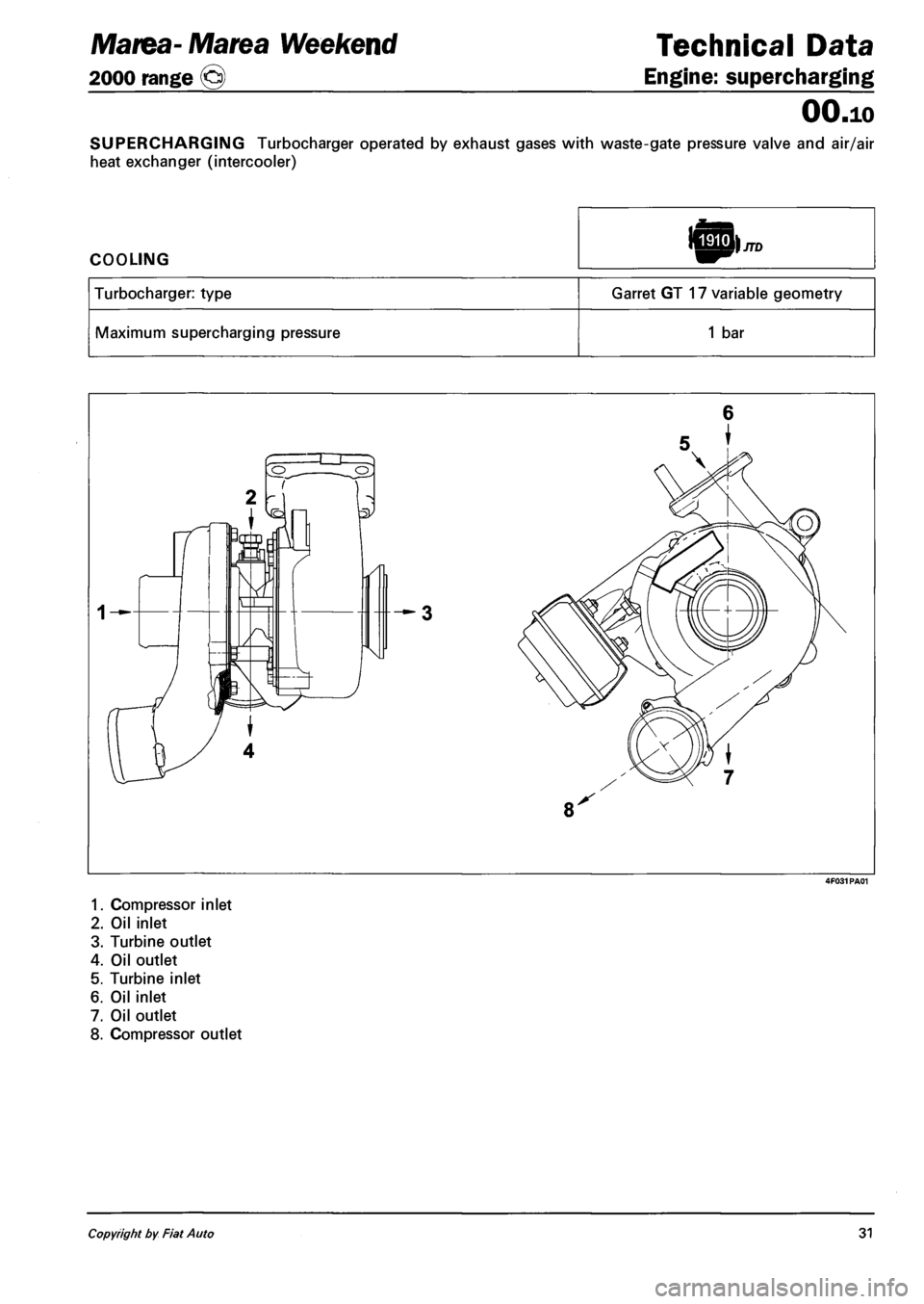
SUPERCHARGING Turbocharger operated by exhaust gases with waste-gate pressure valve and air/air
heat exchanger (intercooler)
COOLING
Turbocharger: type Garret GT 17 variable geometry
Maximum supercharging pressure 1 bar
6
5
1. Compressor inlet
2. Oil inlet
3. Turbine outlet
4. Oil outlet
5. Turbine inlet
6. Oil inlet
7. Oil outlet
8. Compressor outlet
Copyright by Fiat Auto 31
Page 67 of 330
Technical data
Engine
JTD 100 CV Marea Weekend {_
2000 range ©
OO.io
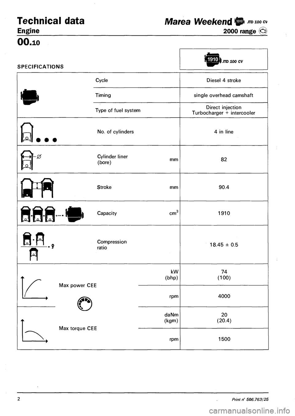
SPECIFICATIONS
ICETTili JTD 100 cv
Cycle
Timing
Type of fuel system
Diesel 4 stroke
single overhead camshaft
Direct injection
Turbocharger + intercooler
9.
No. of cylinders 4 in line
Cylinder liner
(bore) mm 82
Stroke mm 90.4
&8
Capacity cm 1910
Compression
ratio 18.45 ± 0.5
Max power CEE
Max torque CEE
kW
(bhp)
rpm
daNm
(kgm)
rpm
74
(100)
4000
20
(20.4)
1500
2 Print n° 506.763/25
Page 68 of 330
Marea- Marea Weekend • *» Engine
2000 range (§) Fuel feed system
10.
Pages
FUEL FEED SYSTEM
- Engine management system 1
- Diagram showing engine exhaust assem
bly 1
- Fuel anti-evaporation system ~2
- Location of diagnostic socket 2
- Location of injection/ignition system
components in the engine compartment 3
- Front Lambda sensor . 4
- Rear Lambda sensor 4
- Catalytic converter heat shield 5
- Catalytic converter 5
- Exhaust manifold 6
- Electric fuel pump with level sender unit 7
Copyright by Fiat Auto
Page 69 of 330
Marea- Marea Weekend • ^ Engine
2000 range (Q) Fuel feed system
10.
ENGINE MANAGEMENT SYSTEM
The Marea-Marea Weekend 1596 16v has a 4 cylinder in line engine, with 16 valves, 1596 cc, twin over
head camshaft and a Marelli IAW 4EF integrated electronic injection/ignition system.
The fuel system differs from the one described for the 1581 16v "99 range" version through the addition
of several variants to make it compatible with the EEC Stage 3 EOBD regulations.
The main modifications to the system can be summarized as follows:
- Engine management control unit with IAW 4EF
- Catalytic converter near the exhaust manifold to take maximum advantage of the heat of the gases.
- Two Lambda senors, one upstream (front) and one downstream (rear) which check the quality of the
exhaust gases and the operation of the catalyzer.
- Adoption of a timing sensor on the inlet side timing pulley.
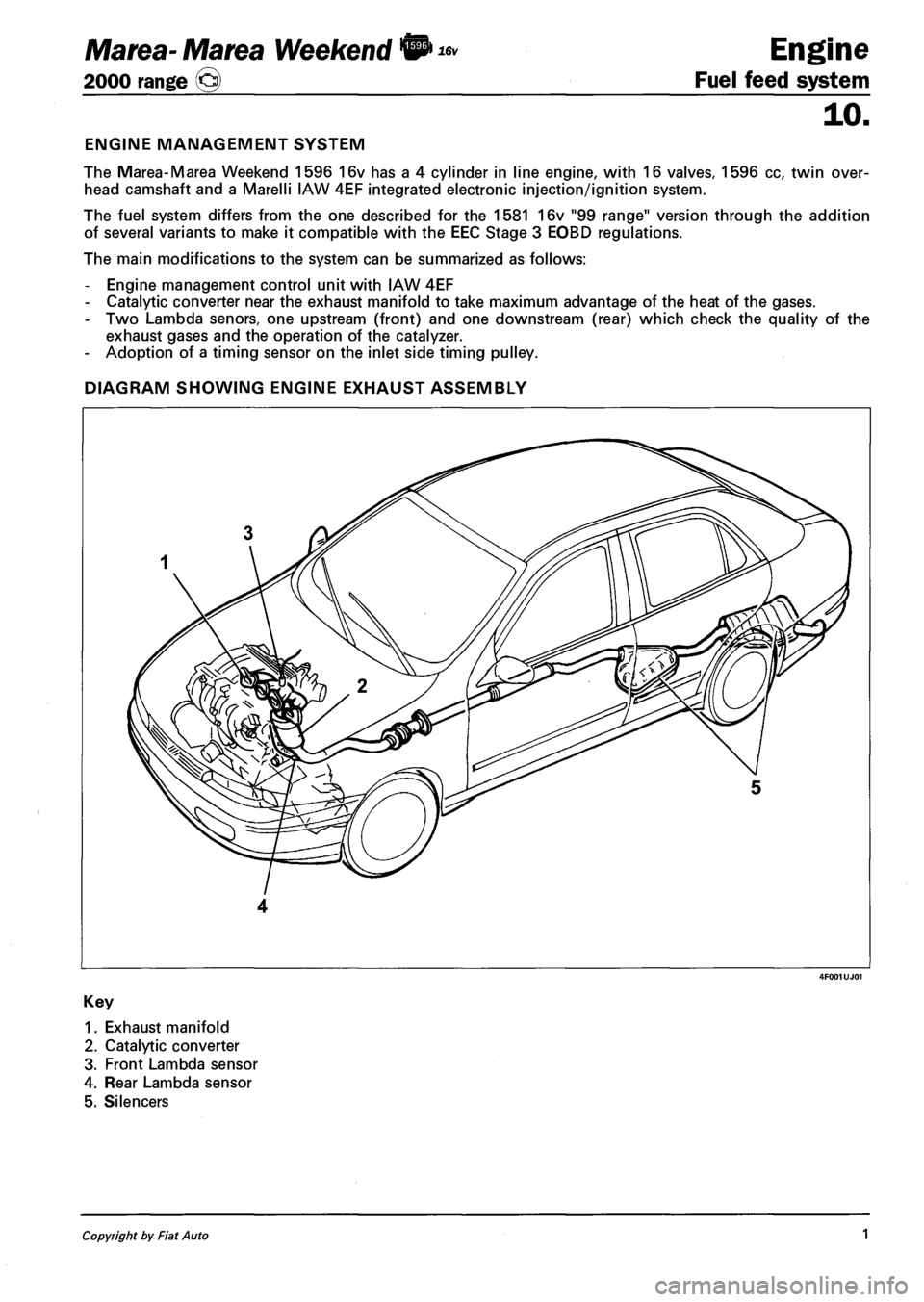
DIAGRAM SHOWING ENGINE EXHAUST ASSEMBLY
1. Exhaust manifold
2. Catalytic converter
3. Front Lambda sensor
4. Rear Lambda sensor
5. Silencers
Copyright by Fiat Auto 1