coolant temperature FIAT MAREA 2001 1.G User Guide
[x] Cancel search | Manufacturer: FIAT, Model Year: 2001, Model line: MAREA, Model: FIAT MAREA 2001 1.GPages: 330
Page 95 of 330
Marea- Marea Weekend 9 ™
2000 range ©) Fuel feed system
Engine
10.
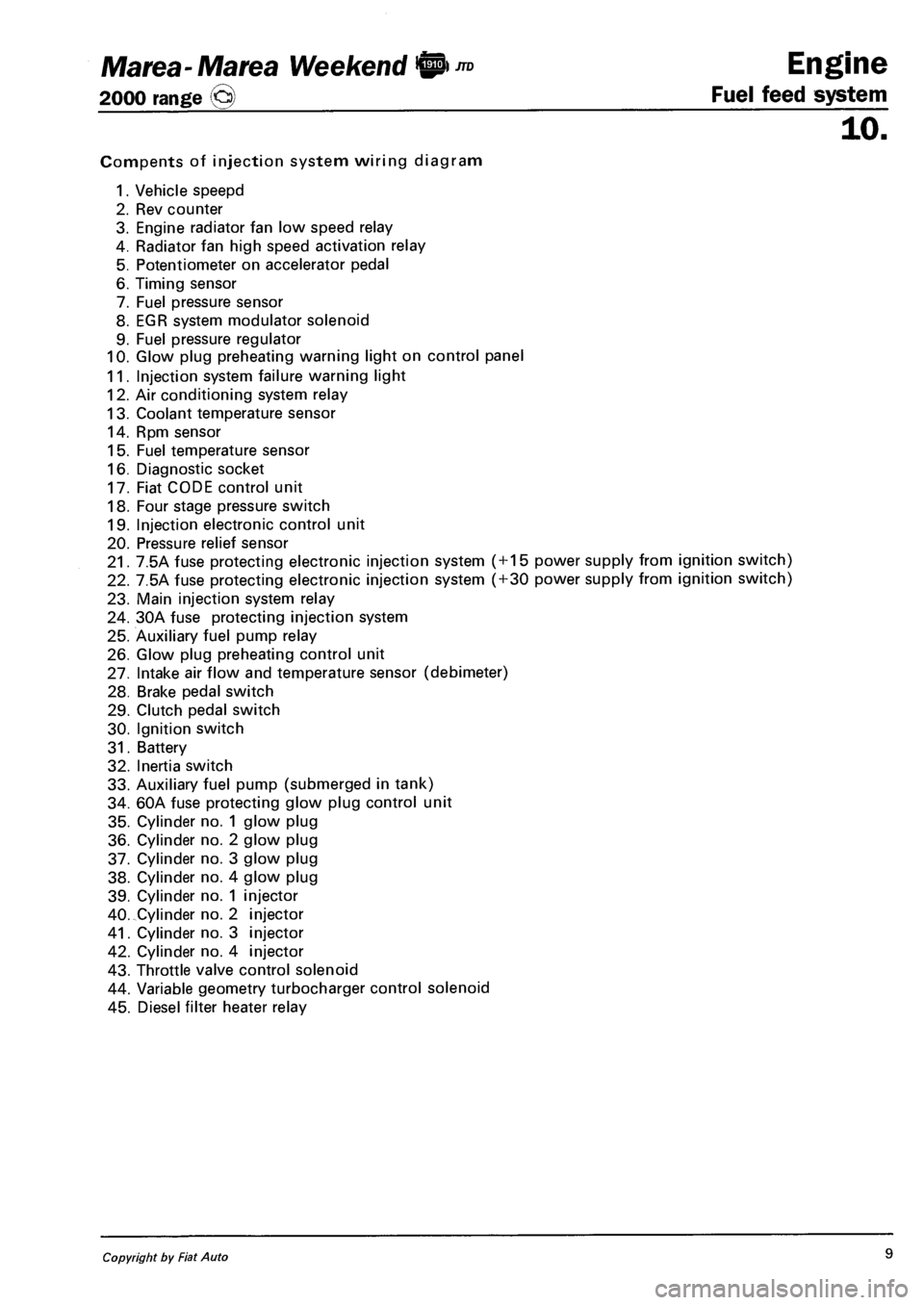
Compents of injection system wiring diagram
1. Vehicle speepd
2. Rev counter
3. Engine radiator fan low speed relay
4. Radiator fan high speed activation relay
5. Potentiometer on accelerator pedal
6. Timing sensor
7. Fuel pressure sensor
8. EGR system modulator solenoid
9. Fuel pressure regulator
10. Glow plug preheating warning light on control panel
11. Injection system failure warning light
12. Air conditioning system relay
13. Coolant temperature sensor
14. Rpm sensor
15. Fuel temperature sensor
16. Diagnostic socket
17. Fiat CODE control unit
18. Four stage pressure switch
19. Injection electronic control unit
20. Pressure relief sensor
21. 7.5A fuse protecting electronic injection system ( + 15 power supply from ignition switch)
22. 7.5A fuse protecting electronic injection system ( + 30 power supply from ignition switch)
23. Main injection system relay
24. 30A fuse protecting injection system
25. Auxiliary fuel pump relay
26. Glow plug preheating control unit
27. Intake air flow and temperature sensor (debimeter)
28. Brake pedal switch
29. Clutch pedal switch
30. Ignition switch
31. Battery
32. Inertia switch
33. Auxiliary fuel pump (submerged in tank)
34. 60A fuse protecting glow plug control unit
35. Cylinder no. 1 glow plug
36. Cylinder no. 2 glow plug
37. Cylinder no. 3 glow plug
38. Cylinder no. 4 glow plug
39. Cylinder no. 1 injector
40. Cylinder no. 2 injector
41. Cylinder no. 3 injector
42. Cylinder no. 4 injector
43. Throttle valve control solenoid
44. Variable geometry turbocharger control solenoid
45. Diesel filter heater relay
Copyright by Fiat Auto 9
Page 97 of 330
Ma tea- Ma tea Weekend !@ ™
2000 range ©
Engine
Fuel feed system
10.
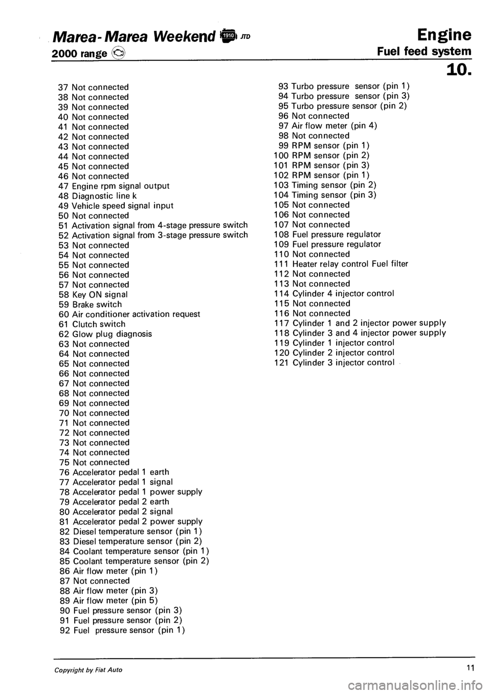
37 Not connected
38 Not connected
39 Not connected
40 Not connected
41 Not connected
42 Not connected
43 Not connected
44 Not connected
45 Not connected
46 Not connected
47 Engine rpm signal output
48 Diagnostic line k
49 Vehicle speed signal input
50 Not connected
51 Activation signal from 4-stage pressure switch
52 Activation signal from 3-stage pressure switch
53 Not connected
54 Not connected
55 Not connected
56 Not connected
57 Not connected
58 Key ON signal
59 Brake switch
60 Air conditioner activation request
61 Clutch switch
62 Glow plug diagnosis
63 Not connected
64 Not connected
65 Not connected
66 Not connected
67 Not connected
68 Not connected
69 Not connected
70 Not connected
71 Not connected
72 Not connected
73 Not connected
74 Not connected
75 Not connected
76 Accelerator pedal 1 earth
77 Accelerator pedal 1 signal
78 Accelerator pedal 1 power supply
79 Accelerator pedal 2 earth
80 Accelerator pedal 2 signal
81 Accelerator pedal 2 power supply
82 Diesel temperature sensor (pin 1)
83 Diesel temperature sensor (pin 2)
84 Coolant temperature sensor (pin 1)
85 Coolant temperature sensor (pin 2)
86 Air flow meter (pin 1)
87 Not connected
88 Air flow meter (pin 3)
89 Air flow meter (pin 5)
90 Fuel pressure sensor (pin 3)
91 Fuel pressure sensor (pin 2)
92 Fuel pressure sensor (pin 1)
93 Turbo pressure sensor (pin 1)
94 Turbo pressure sensor (pin 3)
95 Turbo pressure sensor (pin 2)
96 Not connected
97 Air flow meter (pin 4)
98 Not connected
99 RPM sensor (pin 1)
100 RPM sensor (pin 2)
101 RPM sensor (pin 3)
102 RPM sensor (pin 1)
103 Timing sensor (pin 2)
104 Timing sensor (pin 3)
105 Not connected
106 Not connected
107 Not connected
108 Fuel pressure regulator
109 Fuel pressure regulator
110 Not connected
111 Heater relay control Fuel filter
112 Not connected
113 Not connected
114 Cylinder 4 injector control
115 Not connected
116 Not connected
117 Cylinder 1 and 2 injector power supply
118 Cylinder 3 and 4 injector power supply
119 Cylinder 1 injector control
120 Cylinder 2 injector control
121 Cylinder 3 injector control
Copyright by Fiat Auto 11
Page 101 of 330
Marea- Marea Weekend 9™
2000 range (§)
4F015XJ03
Engine
Fuel feed system
ijo.
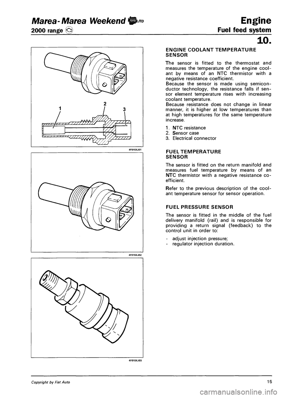
ENGINE COOLANT TEMPERATURE
SENSOR
The sensor is fitted to the thermostat and
measures the temperature of the engine cool
ant by means of an NTC thermistor with a
negative resistance coefficient.
Because the sensor is made using semicon
ductor technology, the resistance falls if sen
sor element temperature rises with increasing
coolant temperature.
Because resistance does not change in linear
manner, it is higher at low temperatures than
at high temperatures for the same temperature
increase.
1. NTC resistance
2. Sensor case
3. Electrical connector
FUEL TEMPERATURE
SENSOR
The sensor is fitted on the return manifold and
measures fuel temperature by means of an
NTC thermistor with a negative resistance co
efficient.
Refer to the previous description of the cool
ant temperature sensor for sensor operation.
FUEL PRESSURE SENSOR
The sensor is fitted in the middle of the fuel
delivery manifold (rail) and is responsible for
providing a return signal (feedback) to the
control unit in order to:
- adjust injection pressure;
- regulator injection duration.
Copyright by Fiat Auto 15
Page 114 of 330
Engine Marea- Marea Weekend IP ™
Fuel feed system 2000 range o
10.
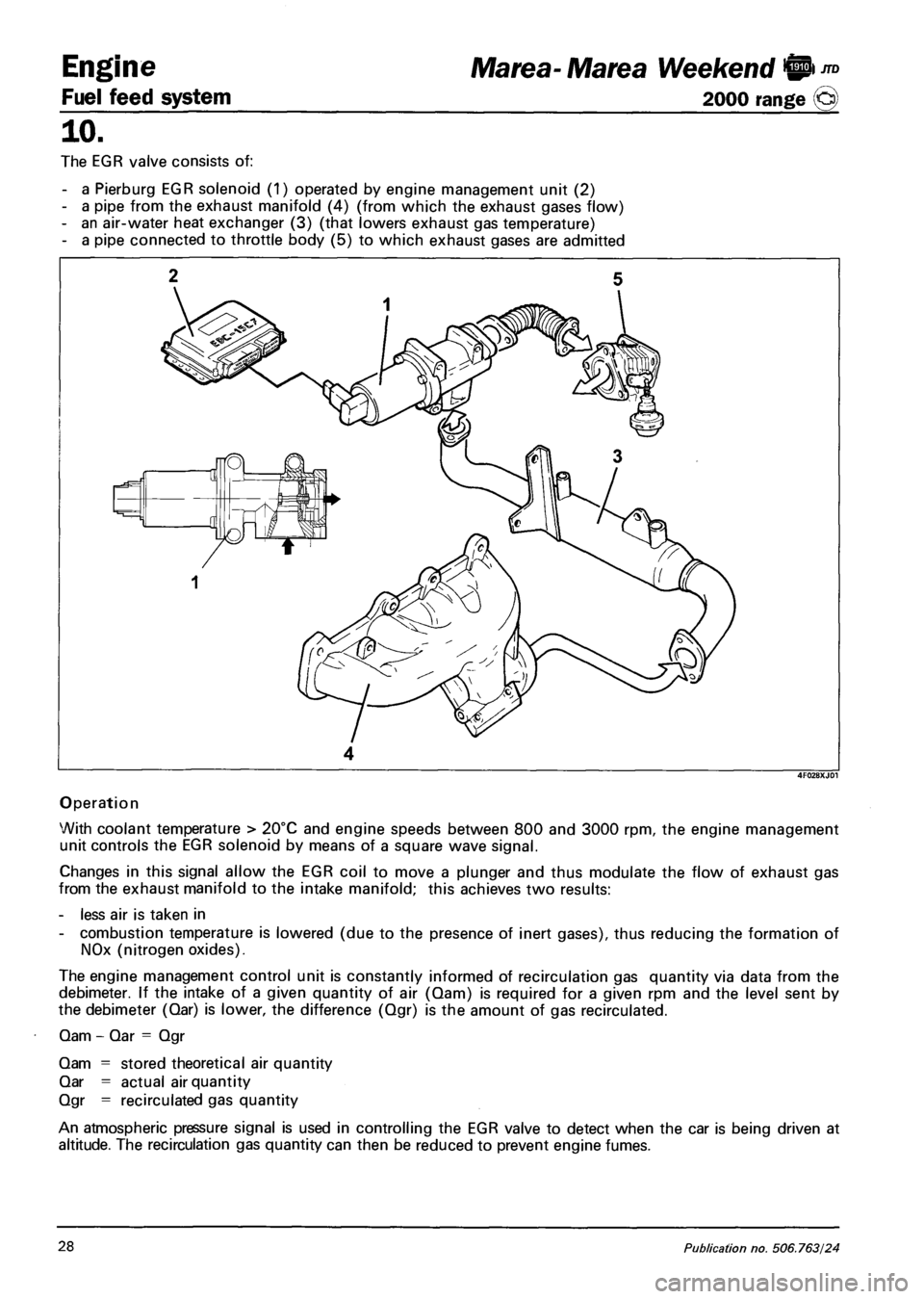
The EGR valve consists of:
- a Pierburg EGR solenoid (1) operated by engine management unit (2)
- a pipe from the exhaust manifold (4) (from which the exhaust gases flow)
- an air-water heat exchanger (3) (that lowers exhaust gas temperature)
- a pipe connected to throttle body (5) to which exhaust gases are admitted
4
Operation
With coolant temperature > 20°C and engine speeds between 800 and 3000 rpm, the engine management
unit controls the EGR solenoid by means of a square wave signal.
Changes in this signal allow the EGR coil to move a plunger and thus modulate the flow of exhaust gas
from the exhaust manifold to the intake manifold; this achieves two results:
- less air is taken in
- combustion temperature is lowered (due to the presence of inert gases), thus reducing the formation of
NOx (nitrogen oxides).
The engine management control unit is constantly informed of recirculation gas quantity via data from the
debimeter. If the intake of a given quantity of air (Qam) is required for a given rpm and the level sent by
the debimeter (Qar) is lower, the difference (Qgr) is the amount of gas recirculated.
Qam - Qar = Qgr
Qam = stored theoretical air quantity
Qar = actual air quantity
Qgr = recirculated gas quantity
An atmospheric pressure signal is used in controlling the EGR valve to detect when the car is being driven at
altitude. The recirculation gas quantity can then be reduced to prevent engine fumes.
28 Publication no. 506.763/24
Page 144 of 330
Electrical equipment
Instrument panel
Marea-Marea Weekend
2000 range ©
55.
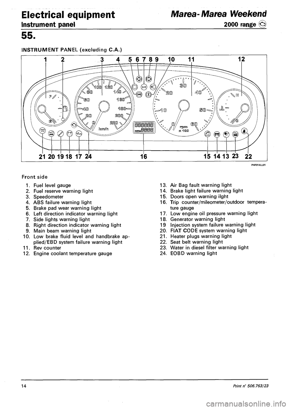
INSTRUMENT PANEL (excluding C.A.)
3 4 56789 10 11 12
21 20 1918 17 24 16 15 14 13 23 22
Front side
1. Fuel level gauge
2. Fuel reserve warning light
3. Speedometer
4. ABS failure warning light
5. Brake pad wear warning light
6. Left direction indicator warning light
7. Side lights warning light
8. Right direction indicator warning light
9. Main beam warning light
10. Low brake fluid level and handbrake ap-
plied/EBD system failure warning light
11. Rev counter
12. Engine coolant temperature gauge
13. Air Bag fault warning light
14. Brake light failure warning light
15. Doors open warning ilght
16. Trip counter/mileometer/outdoor tempera
ture gauge
17. Low engine oil pressure warning light
18. Generator warning light
19 Injection system failure warning light
20. FIAT CODE system warning light
21. Heater plugs warning light
22. Seat belt warning light
23. Water in diesel filter warning light
24. EOBD warning light
14 Print rf 506.763/23
Page 145 of 330
Marea- Marea Weekend
2000 range ©
Electrical equipment
Control module
55.
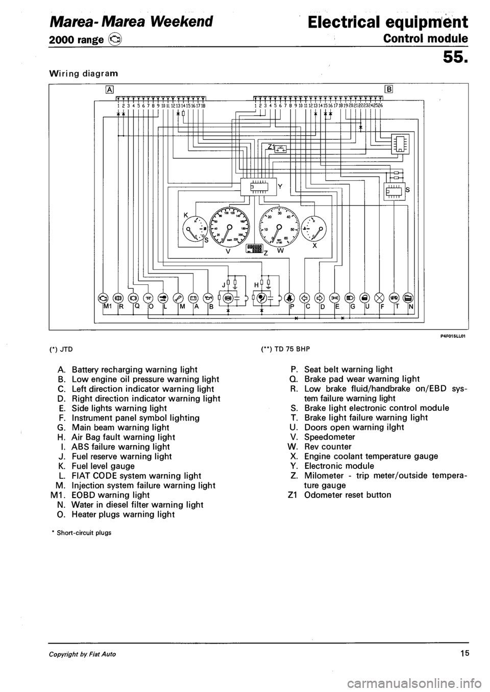
Wiring diagram
.mrmmmL 18 3 4 5 6 7 8 9 10 U 1213 1415161718 |TTTTrTrrrrTTTTT1.TTTTT1pmL 18 3 4 5 6 7 8 9 10 11 121314151617181920213223248586
n ti
O Mill
(*) JTD
A. Battery recharging warning light
B. Low engine oil pressure warning light
C. Left direction indicator warning light
D. Right direction indicator warning light
E. Side lights warning light
F. Instrument panel symbol lighting
G. Main beam warning light
H. Air Bag fault warning light
I. ABS failure warning light
J. Fuel reserve warning light
K. Fuel level gauge
L. FIAT CODE system warning light
M. Injection system failure warning light
M1. EOBD warning light
N. Water in diesel filter warning light
O. Heater plugs warning light
(**) TD 75 BHP
P. Seat belt warning light
Q. Brake pad wear warning light
R. Low brake fluid/handbrake on/EBD sys
tem failure warning light
S. Brake light electronic control module
T. Brake light failure warning light
U. Doors open warning ilght
V. Speedometer
W. Rev counter
X. Engine coolant temperature gauge
Y. Electronic module
Z. Milometer - trip meter/outside tempera
ture gauge
Z1 Odometer reset button
* Short-circuit plugs
Copyright by Fiat Auto 15
Page 146 of 330
Electrical equipment
Instrument panel
Marea- Marea Weekend
2000 range ©
55.
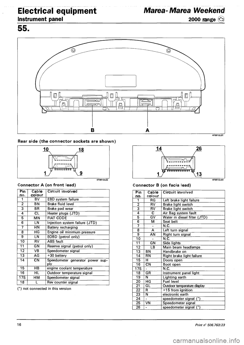
Rear side (the connector sockets are shown)
Connector A (on front lead) Connector B (on facia lead)
Pin no. Cable colour Circuit involved
1 BV EBD system failure
2 BN Brake fluid level
3 BR Brake pad wear
4 CL Heater plugs (JTD)
5 MN FIAT CODE
6 LN Injection system failure (JTD)
7 HN Battery recharging
8 HG Engine oil minimum pressure
9 LN EOBD (petrol only)
10 RV ABS fault
11 GN Reserve signal (petrol only)
12 VB Speedometer signal
13 AG +30 battery
14 CN Speedometer generator power supply
15 HB engine coolant temperature
16 HL Outdoor temperature signal
17S HM Speedometer signal
18 L Rev counter signal
(*) not connected in this version
Pin no. Cable colour Circuit involved
1 RG Left brake light failure
2 RV Brake light switch
3 RV Brake light switch
4 C Air Bag system fault
5 GV Water in diesel filter (JTD)
6 M Seat belt
7 -N.C.
8 A Left turn signal
9 AN Right turn signal
10 -N.C.
11 GN Side lights
12 LB Main beam headlamps
13 BN Handbrake on
14 RN Right brake light failure
15 H Doors open
16 CN Boot open
17S -N.C.
18 GR Instrument panel light
19 N Lighting earth
20 HG Fuel level
21 GL Outdoor temperature display
22 R +15 from ignition
23 N electronic earth
24 -speedometer signal (*)
25 VN Speedometer signal
26 -speedometer signal (*)
16 Print n° 506.763/23
Page 147 of 330
Marea- Marea Weekend Electrical equipment
2000 range (Q) Control module
55.
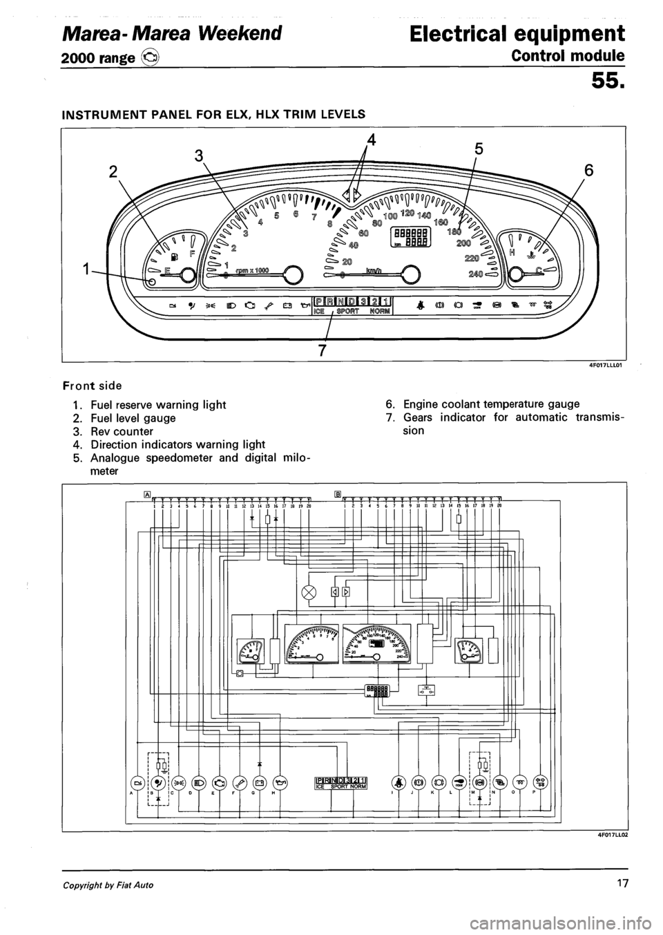
Front side
1. Fuel reserve warning light
2. Fuel level gauge
3. Rev counter
4. Direction indicators warning light
5. Analogue speedometer and digital milo
meter
6. Engine coolant temperature gauge
7. Gears indicator for automatic transmis
sion
Copyright by Fiat Auto 17
Page 148 of 330
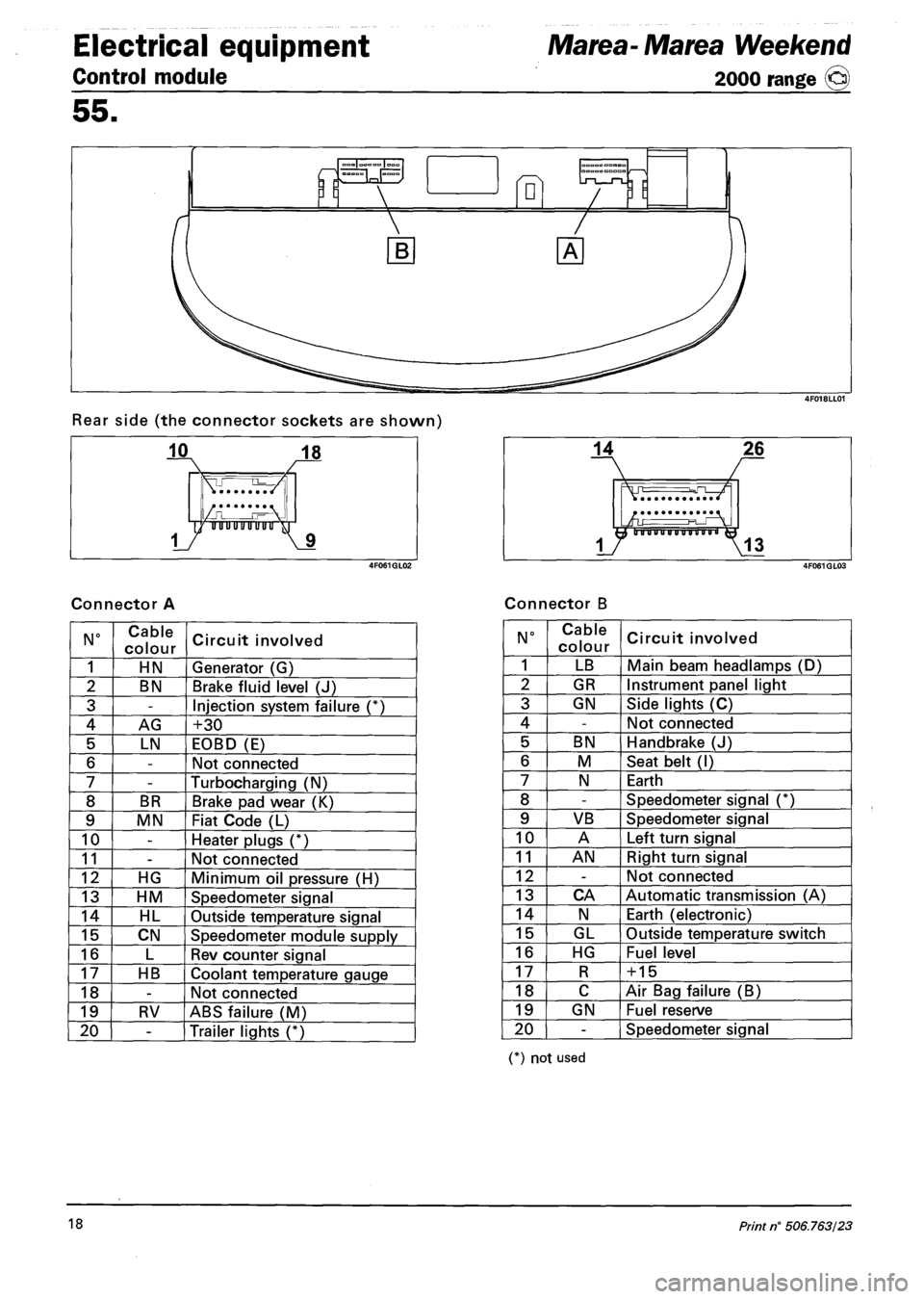
Electrical equipment
Control module
Marea- Marea Weekend
2000 range ©
55.
Rear side (the connector sockets are shown)
Connector A Connector B
N° Cable
colour Circuit involved
1 HN Generator (G)
2 BN Brake fluid level (J)
3 -Injection system failure (*)
4 AG +30
5 LN EOBD (E)
6 -Not connected
7 -Turbocharging (N)
8 BR Brake pad wear (K)
9 MN Fiat Code (L)
10 -Heater plugs (*)
11 -Not connected
12 HG Minimum oil pressure (H)
13 HM Speedometer signal
14 HL Outside temperature signal
15 CN Speedometer module supply
16 L Rev counter signal
17 HB Coolant temperature gauge
18 -Not connected
19 RV ABS failure (M)
20 -Trailer lights (*)
N° Cable
colour Circuit involved
1 LB Main beam headlamps (D)
2 GR Instrument panel light
3 GN Side lights (C)
4 -Not connected
5 BN Handbrake (J)
6 M Seat belt (I)
7 N Earth
8 -Speedometer signal (*)
9 VB Speedometer signal
10 A Left turn signal
11 AN Right turn signal
12 -Not connected
13 CA Automatic transmission (A)
14 N Earth (electronic)
15 GL Outside temperature switch
16 HG Fuel level
17 R + 15
18 C Air Bag failure (B)
19 GN Fuel reserve
20 -Speedometer signal
(*) not used
18 Print n° 506.763/23
Page 187 of 330
Marea- Marea Weekend
2000 range ©
Electrical equipment
Wiring diagrams
55.
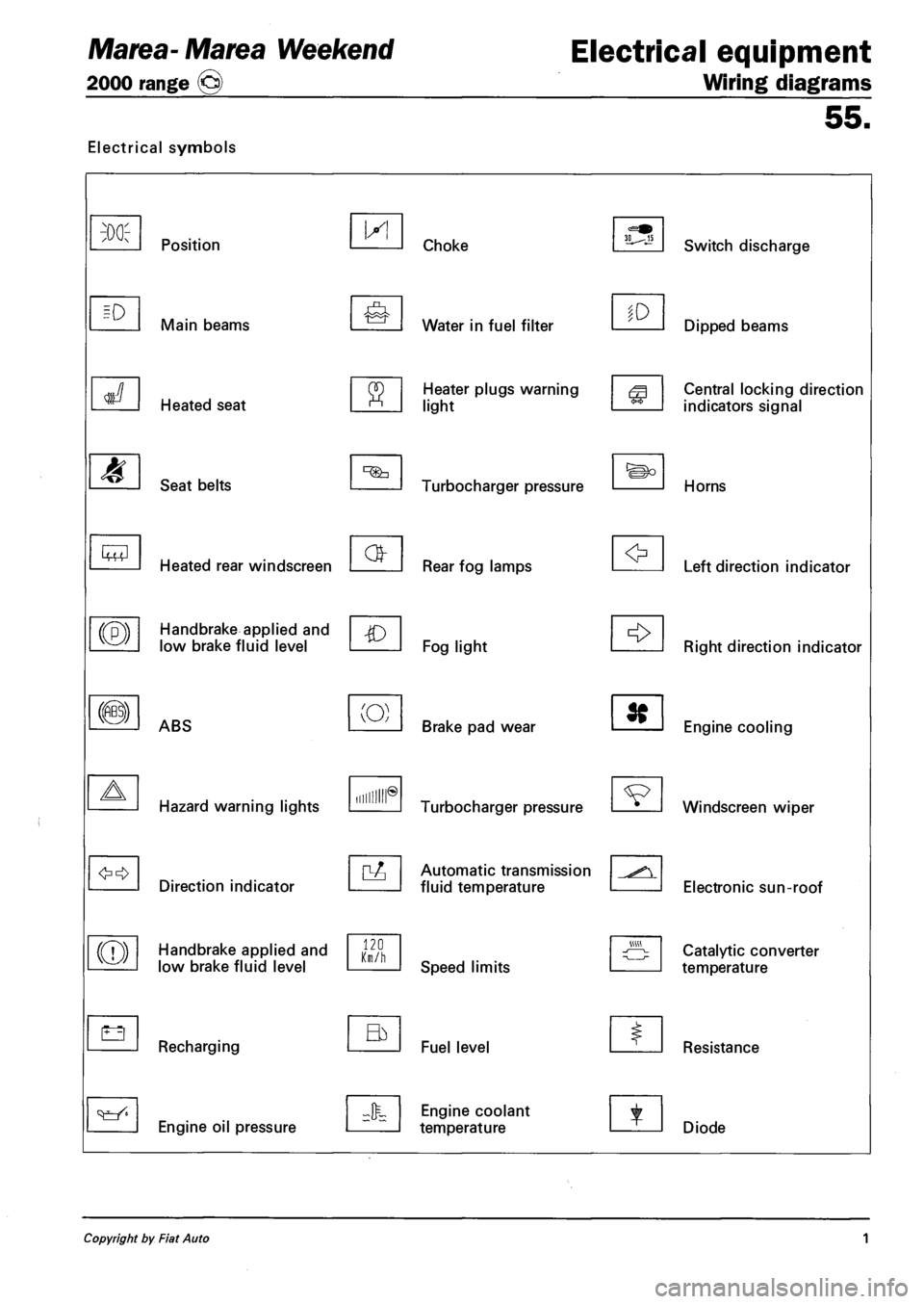
Electrical symbols
M
Lt3
Position
Main beams
Heated seat
Seat belts
Heated rear windscreen
Handbrake applied and
low brake fluid level
ABS
Hazard warning lights
Direction indicator
Handbrake applied and
low brake fluid level
Recharging
Engine oil pressure
IX!
(O)
Hum®
120 Km/h
Choke
Water in fuel filter
Heater plugs warning
light
Turbocharger pressure
Rear fog lamps
Fog light
Brake pad wear
Turbocharger pressure
Automatic transmission
fluid temperature
Speed limits
Fuel level
Engine coolant
temperature
to
Switch discharge
Dipped beams
Central locking direction
indicators signal
Horns
Left direction indicator
Right direction indicator
Engine cooling
Windscreen wiper
Electronic sun-roof
Catalytic converter
temperature
Resistance
Diode
Copyright by Fiat Auto 1