relay FIAT MAREA 2001 1.G User Guide
[x] Cancel search | Manufacturer: FIAT, Model Year: 2001, Model line: MAREA, Model: FIAT MAREA 2001 1.GPages: 330
Page 130 of 330
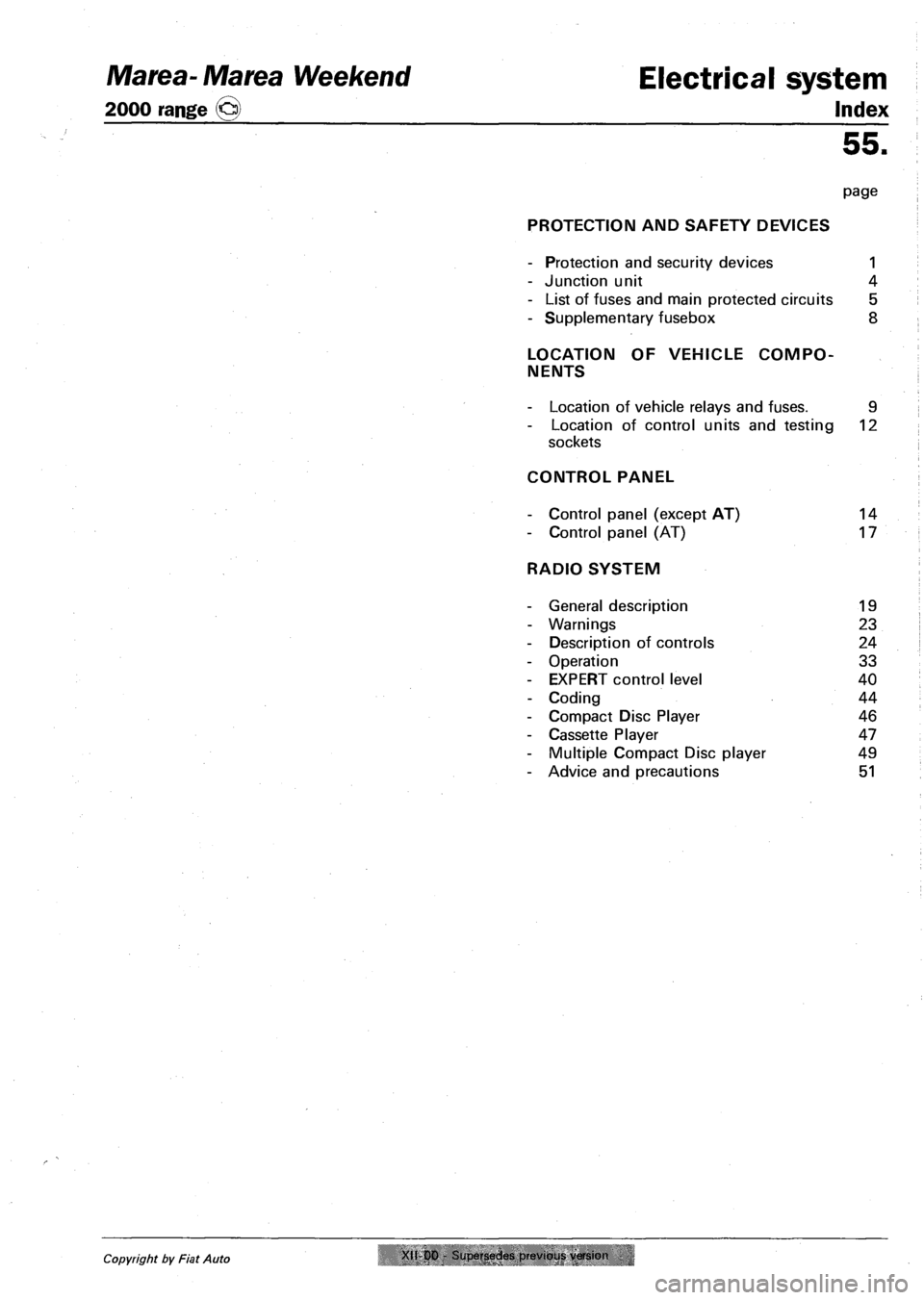
Marea-Marea Weekend Electrical system
2000 range (§) Index
55.
page
PROTECTION AND SAFETY DEVICES
- Protection and security devices 1
- Junction unit 4
- List of fuses and main protected circuits 5
- Supplementary fusebox 8
LOCATION OF VEHICLE COMPO
NENTS
- Location of vehicle relays and fuses. 9
- Location of control units and testing 12
sockets
CONTROL PANEL
- Control panel (except AT) 14
- Control panel (AT) 17
RADIO SYSTEM
- General description 19
- Warnings 23
- Description of controls 24
- Operation 33
- EXPERT control level 40
- Coding 44
- Compact Disc Player 46
- Cassette Player 47
- Multiple Compact Disc player 49
- Advice and precautions 51
Copyright by Fiat Auto XII-00 Supersedes previous, version
Page 132 of 330
Electrical equipment
Protection and safety devices
Marea- Marea Weekend
2000 range ©)
55.
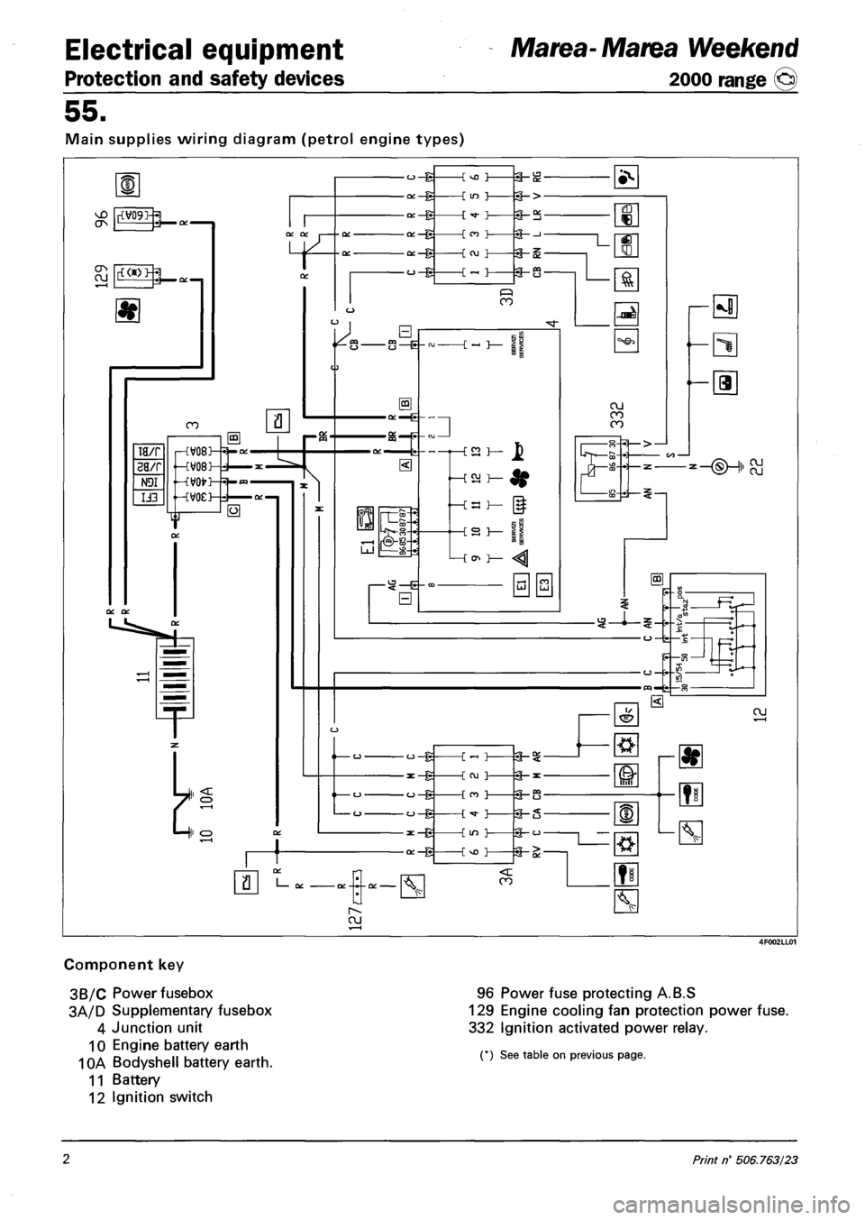
Main supplies wiring diagram (petrol engine types)
Component key
3B/C Power fusebox
3A/D Supplementary fusebox
4 Junction unit
10 Engine battery earth
10A Bodyshell battery earth.
11 Battery
12 Ignition switch
96 Power fuse protecting A.B.S
129 Engine cooling fan protection power fuse.
332 Ignition activated power relay.
(*) See table on previous page.
2 Print n° 506.763/23
Page 133 of 330
Marea- Marea Weekend
2000 range ©)
Electrical equipment
Protection and safety devices
55.
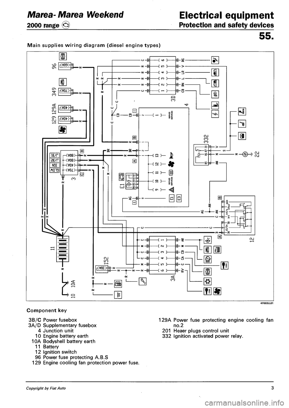
Main supplies wiring diagram (diesel engine types)
Component key
3B/C Power fusebox
3A/D Supplementary fusebox
4 Junction unit
10 Engine battery earth
10A Bodyshell battery earth
11 Battery
12 Ignition switch
96 Power fuse protecting A.B.S
129 Engine cooling fan protection power fuse.
129A Power fuse protecting engine cooling fan
no.2
201 Heaer plugs control unit
332 Ignition activated power relay.
Copyright by Fiat Auto 3
Page 134 of 330
Electrical equipment
Junction unit
Marea-Marea Weekend
2000 range ©
55.
Junction unit
»F11=
~T~ II l;
•F9° |["^FT^1| °F10°ir°F13=
| ^14=- ir=F15«=- II
»F12=
SLHHItHia r i i i •
3F4= ir^F8=1l =F7="|| °F6 = 1
I I I I I 1 I '
14 5 4 12-
lor
1-11-J
I 1
J 7_
a o_o o_o OLD n.
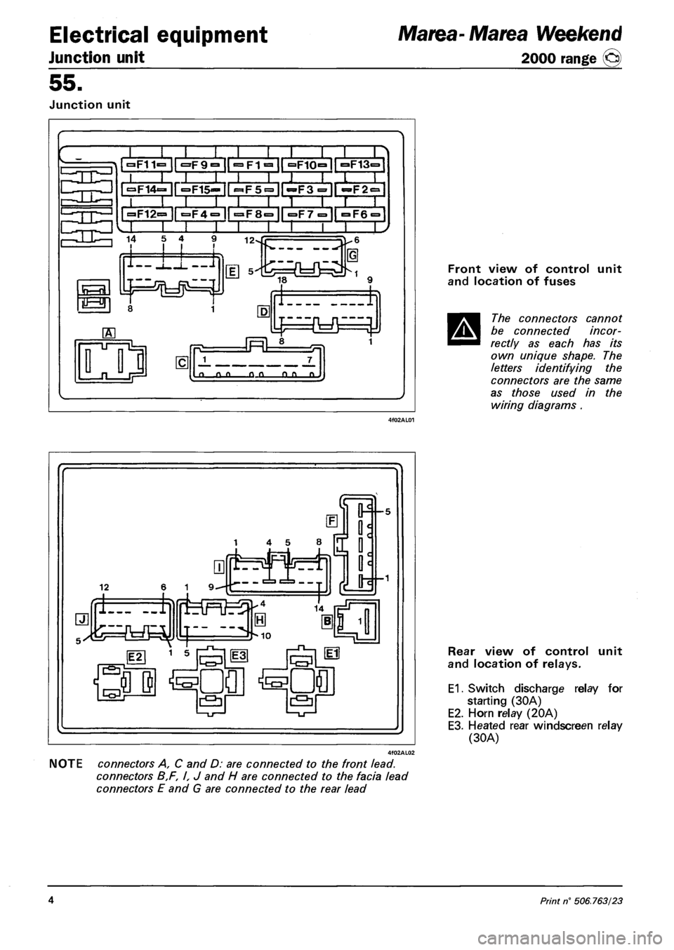
Front view of control unit
and location of fuses
The connectors cannot
be connected incor
rectly as each has its
own unique shape. The
letters identifying the
connectors are the same
as those used in the
wiring diagrams .
NOTE connectors A, C and D: are connected to the front lead.
connectors B,F, I, J and H are connected to the facia lead
connectors E and G are connected to the rear lead
Rear view of control unit
and location of relays.
E1. Switch discharge relay for
starting (30A)
E2. Horn relay (20A)
E3. Heated rear windscreen relay
(30A)
4 Print n° 506.763/23
Page 135 of 330
Marea-Marea Weekend
2000 range Q
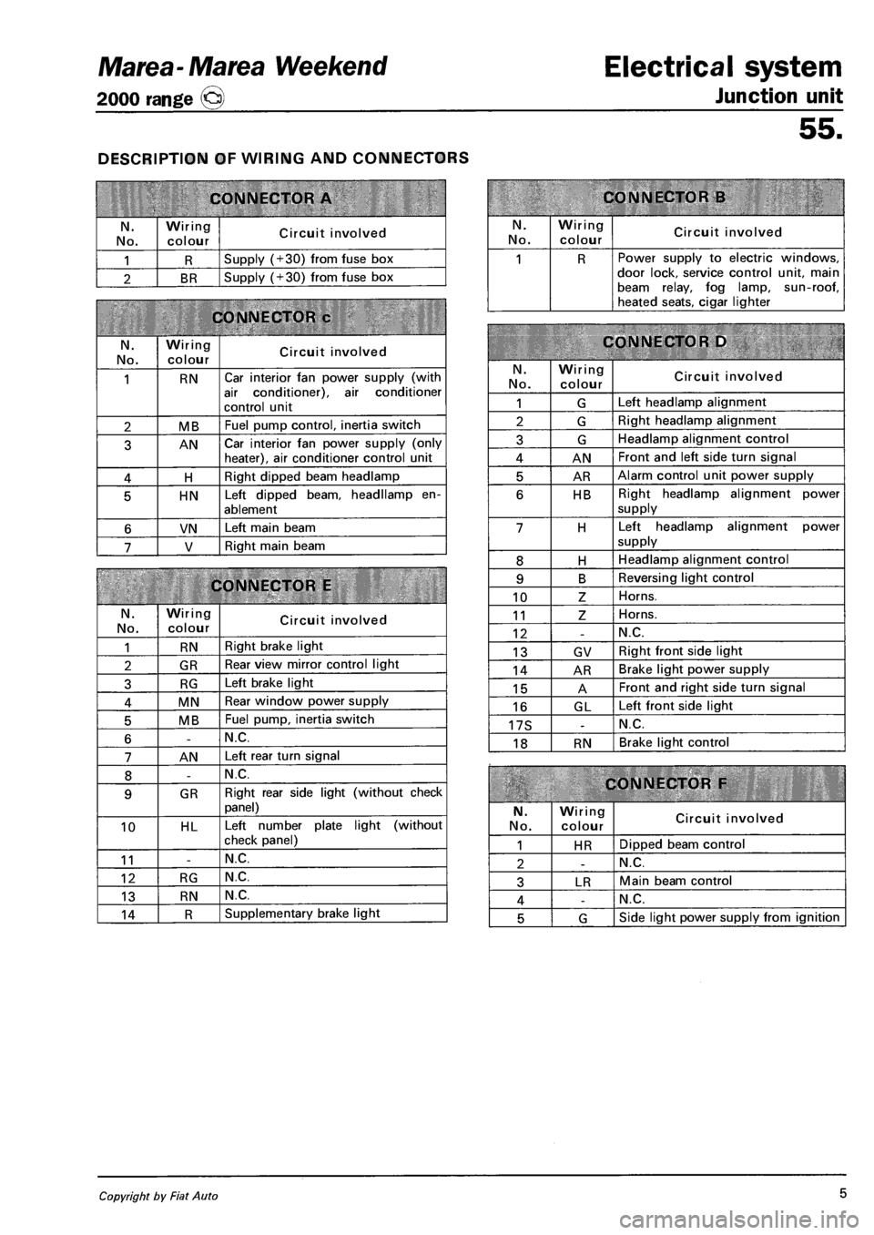
DESCRIPTION OF WIRING AND CONNECTORS
CONNECTOR A
N.
No.
Wiring
colour Circuit involved
1 R Supply (+30) from fuse box
2 BR Supply (+30) from fuse box
CONNECTOR c
N. No.
Wiring colour Circuit involved
1 RN Car interior fan power supply (with
air conditioner), air conditioner
control unit
2 MB Fuel pump control, inertia switch
3 AN Car interior fan power supply (only heater), air conditioner control unit
4 H Right dipped beam headlamp
5 HN Left dipped beam, headllamp en
ablement
6 VN Left main beam
7 V Right main beam
CONNECTOR E
N.
No.
Wiring colour Circuit involved
1 RN Right brake light
2 GR Rear view mirror control light
3 RG Left brake light
4 MN Rear window power supply
5 MB Fuel pump, inertia switch
6 -N.C.
7 AN Left rear turn signal
8 -N.C.
9 GR Right rear side light (without check
panel)
10 HL Left number plate light (without
check panel)
11 -N.C.
12 RG N.C.
13 RN N.C.
14 R Supplementary brake light
Electrical system
Junction unit
55.
CONNECTOR B
N. No.
Wiring
colour Circuit involved
1 R Power supply to electric windows, door lock, service control unit, main beam relay, fog lamp, sun-roof, heated seats, cigar lighter
CONNECTOR D
N.
No.
Wiring colour Circuit involved
1 G Left headlamp alignment
2 G Right headlamp alignment
3 G Headlamp alignment control
4 AN Front and left side turn signal
5 AR Alarm control unit power supply
6 HB Right headlamp alignment power
supply
7 H Left headlamp alignment power
supply
8 H Headlamp alignment control
9 B Reversing light control
10 Z Horns.
11 Z Horns.
12 -N.C.
13 GV Right front side light
14 AR Brake light power supply
15 A Front and right side turn signal
16 GL Left front side light
17S -N.C.
18 RN Brake light control
CONNECTOR F
N.
No.
Wiring colour Circuit involved
1 HR Dipped beam control
2 -N.C.
3 LR Main beam control
4 -N.C.
5 G Side light power supply from ignition
Copyright by Fiat Auto 5
Page 139 of 330
Marea-Marea Weekend Electrical equipment
2000 range (§) Location of components on the car
55.
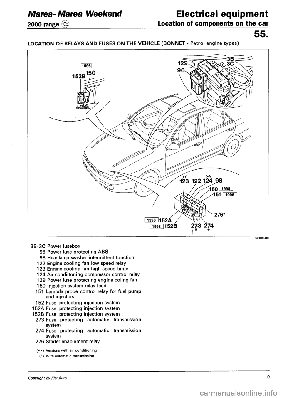
LOCATION OF RELAYS AND FUSES ON THE VEHICLE (BONNET - Petrol engine types)
Fi998l152B 273 274 i * *
3B-3C Power fusebox
96 Power fuse protecting ABS
98 Headlamp washer intermittent function
122 Engine cooling fan low speed relay
123 Engine cooling fan high speed timer
124 Air condiitoning compressor control relay
129 Power fuse protecting engine coling fan
150 Injection system relay feed
151 Lambda probe control relay for fuel pump
and injectors
152 Fuse protecting injection system
152A Fuse protecting injection system
152B Fuse protecting injection system
273 Fuse protecting automatic transmission
system
274 Fuse protecting automatic transmission
system
276 Starter enablement relay
(••) Versions with air conditioning
(*) With automatic transmission
Copyright by Fiat Auto 9
Page 140 of 330
Electrical equipment Marea-Marea Weekend
Location of components on the car 2000 range (§)
55.
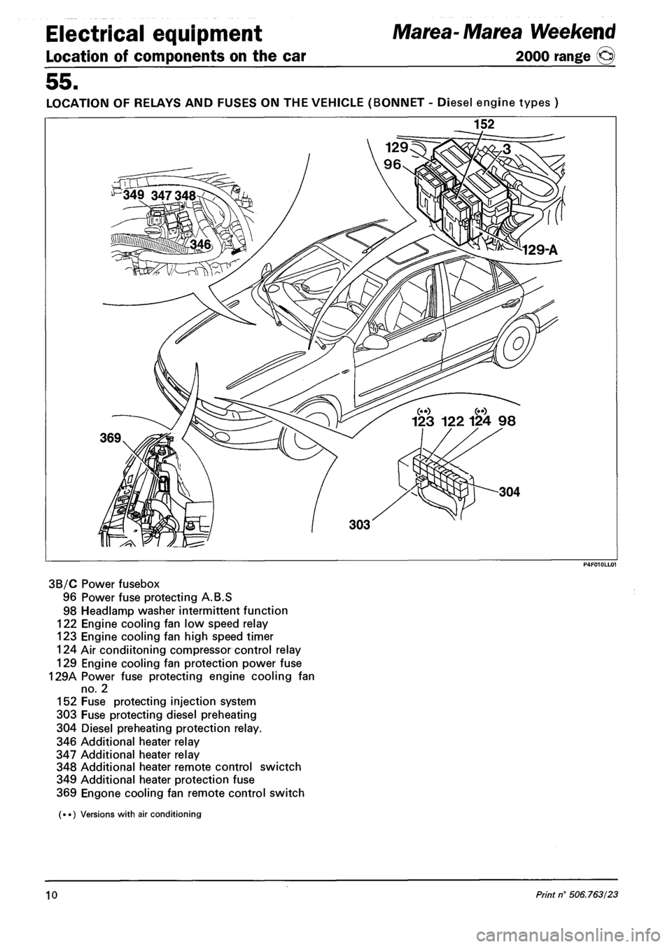
LOCATION OF RELAYS AND FUSES ON THE VEHICLE (BONNET - Diesel engine types )
152
3B/C Power fusebox
96 Power fuse protecting A.B.S
98 Headlamp washer intermittent function
122 Engine cooling fan low speed relay
123 Engine cooling fan high speed timer
124 Air condiitoning compressor control relay
129 Engine cooling fan protection power fuse
129A Power fuse protecting engine cooling fan
no. 2
152 Fuse protecting injection system
303 Fuse protecting diesel preheating
304 Diesel preheating protection relay.
346 Additional heater relay
347 Additional heater relay
348 Additional heater remote control swictch
349 Additional heater protection fuse
369 Engone cooling fan remote control switch
(••) Versions with air conditioning
10 Print n° 506.763/23
Page 141 of 330
Marea-Marea Weekend Electrical equipment
2000 range (§) Location of components on the car
55.
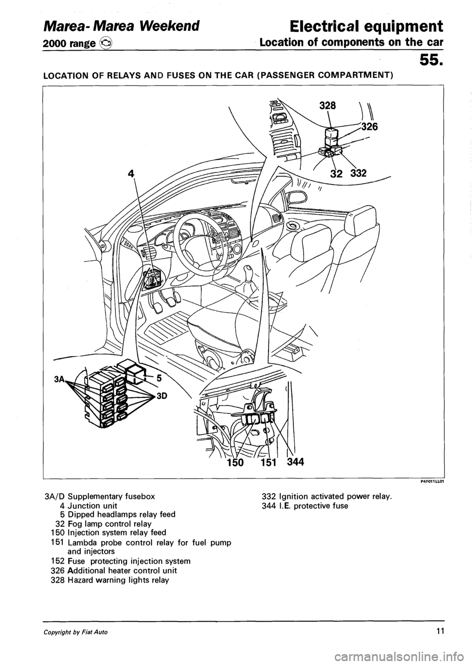
LOCATION OF RELAYS AND FUSES ON THE CAR (PASSENGER COMPARTMENT)
3A/D Supplementary fusebox 332 Ignition activated power relay.
4 Junction unit 344 I.E. protective fuse
5 Dipped headlamps relay feed
32 Fog lamp control relay
150 Injection system relay feed
151 Lambda probe control relay for fuel pump
and injectors
152 Fuse protecting injection system
326 Additional heater control unit
328 Hazard warning lights relay
Copyright by Fiat Auto 11
Page 188 of 330
Electrical equipment
Wiring diagrams
Marea- Marea Weekend
2000 range ©
55.
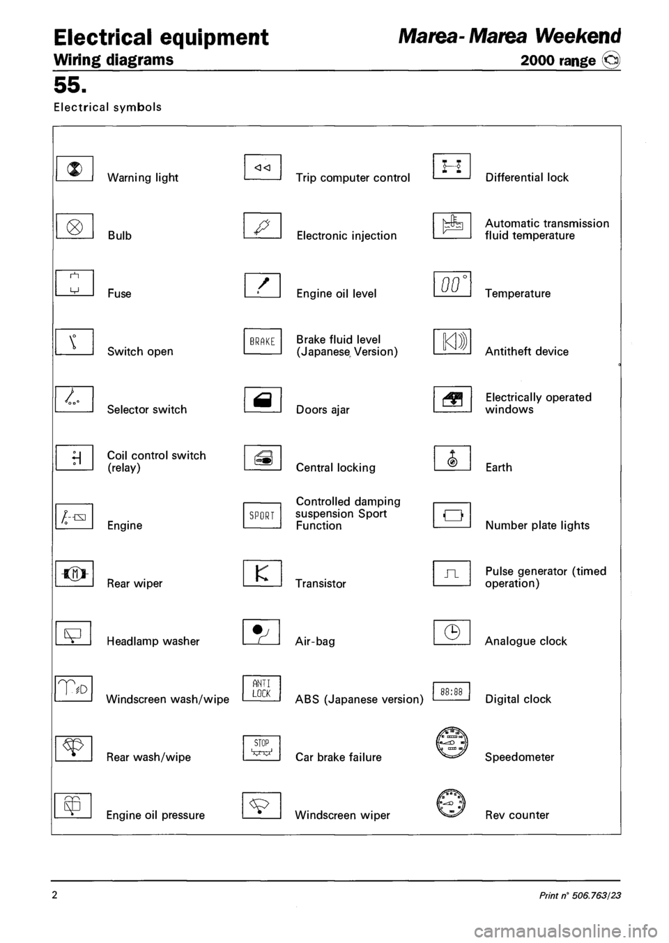
Electrical symbols
Warning light
Bulb
/--txi
T
Fuse
Switch open
Selector switch
Coil control switch
(relay)
Engine
Rear wiper
Headlamp washer
Windscreen wash/wipe
Rear wash/wipe
Engine oil pressure
BRAKE
SPORT
K
ANT I LOCK
STOP
Trip computer control
Electronic injection
Engine oil level
Brake fluid level
(Japanese, Version)
Doors ajar
Central locking
Controlled damping
suspension Sport
Function
Transistor
Air-bag
ABS (Japanese version)
Car brake failure
Windscreen wiper
H Differential lock
Automatic transmission
fluid temperature
00' Temperature
Antitheft device
Electrically operated
windows
Earth
Number plate lights
Pulse generator (timed
operation)
Analogue clock
Digital clock
Speedometer
Rev counter
2 Print n° 506.763/23
Page 192 of 330
4F006ML01
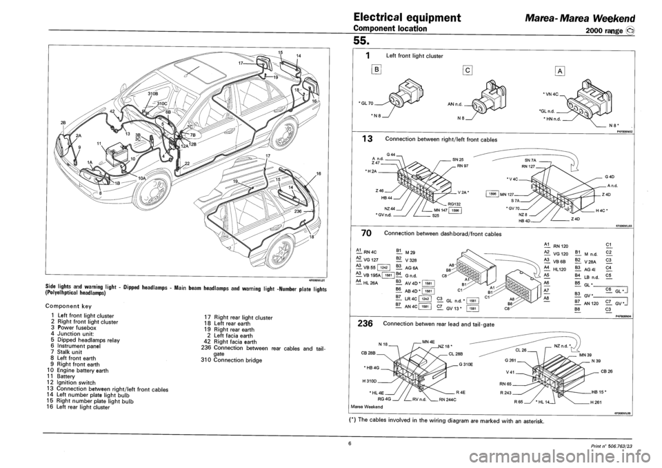
SIDE LIGHTS AND WARNING LIGHT - DIPPED HEADLAMPS - MAIN BEAM HEADLAMPS AND WARNING LIGHT -NUMBER PLATE LIQHTS (POLYELHPTICAL HEADLAMPS) r »
Component key
1 Left front light cluster
2 Right front light cluster
3 Power fusebox
4 Junction unit:
5 Dipped headlamps relay
6 Instrument panel
7 Stalk unit
8 Left front earth
9 Right front earth
10 Engine battery earth
11 Battery
12 Ignition switch
13 Connection between right/left front cables
14 Left number plate light bulb
15 Right number plate light bulb
16 Left rear light cluster
17 Right rear light cluster
18 Left rear earth
19 Right rear earth
2 Left facia earth
42 Right facia earth
236 Connection between rear cables and tail
gate
310 Connection bridge
Electrical equipment
Component location
Marea-Marea Weekend
2000 range (§)
55.
Left front light cluster
B
'GL70
N8'
1 3 Connection between right/left front cables
•H2A
NZ44
* GV n.d.
70 Connection between dashborad/front cables
A1
— RN 4C
— VG 127
B1 M29
^1 VB 55 | 1242
A3
— V328
11 AG6A
VB 195A | 1581 |B4 GN D
^1 HL 26A 11 AV 4D * I 1581
?! AB 4D"
11 LR 4C f
1581
1242
1Z_ AN4C| 1581
RN 120
VG 120
^1 VB6B
£1 HL120
B1 M n.d.
11 V28A
11 AG 41
11 LB n.d.
21
C2_
21
21
C5
B5 GL"
21 GL n.d.
2L GV13*
11 GV*
!T_ AN 120
B8
C6 GL •
2Z_ GV*J
21 P4F808NO4
236 Connection betwen rear lead and tail-gate
CB 28B
CB 26
* HL 4E
RG 4G
Marea Weekend
(*) The cables involved in the wiring diagram are marked with an asterisk.
6 Print n° 506.763/23