temperature sensor FIAT MAREA 2001 1.G User Guide
[x] Cancel search | Manufacturer: FIAT, Model Year: 2001, Model line: MAREA, Model: FIAT MAREA 2001 1.GPages: 330
Page 95 of 330
Marea- Marea Weekend 9 ™
2000 range ©) Fuel feed system
Engine
10.
Compents of injection system wiring diagram
1. Vehicle speepd
2. Rev counter
3. Engine radiator fan low speed relay
4. Radiator fan high speed activation relay
5. Potentiometer on accelerator pedal
6. Timing sensor
7. Fuel pressure sensor
8. EGR system modulator solenoid
9. Fuel pressure regulator
10. Glow plug preheating warning light on control panel
11. Injection system failure warning light
12. Air conditioning system relay
13. Coolant temperature sensor
14. Rpm sensor
15. Fuel temperature sensor
16. Diagnostic socket
17. Fiat CODE control unit
18. Four stage pressure switch
19. Injection electronic control unit
20. Pressure relief sensor
21. 7.5A fuse protecting electronic injection system ( + 15 power supply from ignition switch)
22. 7.5A fuse protecting electronic injection system ( + 30 power supply from ignition switch)
23. Main injection system relay
24. 30A fuse protecting injection system
25. Auxiliary fuel pump relay
26. Glow plug preheating control unit
27. Intake air flow and temperature sensor (debimeter)
28. Brake pedal switch
29. Clutch pedal switch
30. Ignition switch
31. Battery
32. Inertia switch
33. Auxiliary fuel pump (submerged in tank)
34. 60A fuse protecting glow plug control unit
35. Cylinder no. 1 glow plug
36. Cylinder no. 2 glow plug
37. Cylinder no. 3 glow plug
38. Cylinder no. 4 glow plug
39. Cylinder no. 1 injector
40. Cylinder no. 2 injector
41. Cylinder no. 3 injector
42. Cylinder no. 4 injector
43. Throttle valve control solenoid
44. Variable geometry turbocharger control solenoid
45. Diesel filter heater relay
Copyright by Fiat Auto 9
Page 97 of 330
Ma tea- Ma tea Weekend !@ ™
2000 range ©
Engine
Fuel feed system
10.
37 Not connected
38 Not connected
39 Not connected
40 Not connected
41 Not connected
42 Not connected
43 Not connected
44 Not connected
45 Not connected
46 Not connected
47 Engine rpm signal output
48 Diagnostic line k
49 Vehicle speed signal input
50 Not connected
51 Activation signal from 4-stage pressure switch
52 Activation signal from 3-stage pressure switch
53 Not connected
54 Not connected
55 Not connected
56 Not connected
57 Not connected
58 Key ON signal
59 Brake switch
60 Air conditioner activation request
61 Clutch switch
62 Glow plug diagnosis
63 Not connected
64 Not connected
65 Not connected
66 Not connected
67 Not connected
68 Not connected
69 Not connected
70 Not connected
71 Not connected
72 Not connected
73 Not connected
74 Not connected
75 Not connected
76 Accelerator pedal 1 earth
77 Accelerator pedal 1 signal
78 Accelerator pedal 1 power supply
79 Accelerator pedal 2 earth
80 Accelerator pedal 2 signal
81 Accelerator pedal 2 power supply
82 Diesel temperature sensor (pin 1)
83 Diesel temperature sensor (pin 2)
84 Coolant temperature sensor (pin 1)
85 Coolant temperature sensor (pin 2)
86 Air flow meter (pin 1)
87 Not connected
88 Air flow meter (pin 3)
89 Air flow meter (pin 5)
90 Fuel pressure sensor (pin 3)
91 Fuel pressure sensor (pin 2)
92 Fuel pressure sensor (pin 1)
93 Turbo pressure sensor (pin 1)
94 Turbo pressure sensor (pin 3)
95 Turbo pressure sensor (pin 2)
96 Not connected
97 Air flow meter (pin 4)
98 Not connected
99 RPM sensor (pin 1)
100 RPM sensor (pin 2)
101 RPM sensor (pin 3)
102 RPM sensor (pin 1)
103 Timing sensor (pin 2)
104 Timing sensor (pin 3)
105 Not connected
106 Not connected
107 Not connected
108 Fuel pressure regulator
109 Fuel pressure regulator
110 Not connected
111 Heater relay control Fuel filter
112 Not connected
113 Not connected
114 Cylinder 4 injector control
115 Not connected
116 Not connected
117 Cylinder 1 and 2 injector power supply
118 Cylinder 3 and 4 injector power supply
119 Cylinder 1 injector control
120 Cylinder 2 injector control
121 Cylinder 3 injector control
Copyright by Fiat Auto 11
Page 99 of 330
Marea- Marea Weekend 9"°
2000 range ©
Engine
Fuel feed system
10.
TIMING SENSOR
The Hall effect sensor is fitted to the cylinder head and faces the camshaft pulley.
An opening on the pulley allows the timing sensor to detect the engine timing position and indicate it to
the injection control unit.
The injection control unit uses the timing sensor signal to detect TDC at the end of compression.
Operation
A semi-condulator layer, through which a current passes, immersed in a magnetic field (lines of force per
pendicular to the direction of the current), produces a difference in power, known as Hall voltage.
If the intensity of the current remains constant, the voltage produced only depends on the intensity of the
magnetic field. The intensity of the field can simply be altered periodically to produce a modulated electri
cal signal. Signal frequency is proportional to the speed with which the magnetic field changes.
To achieve this change, the sensor is crossed by a metal ring (inner part of the pulley) with an opening.
When it moves, the metal part of the ring covers the sensor to magnetic field and the output signal is
therefore low; Conversely, the sensor generates a high signal at the opening when the magnetic field is
present.
This signal, together with the rpm and TDC signals, allows the injection control unit to identify piston po
sition and determine injection point.
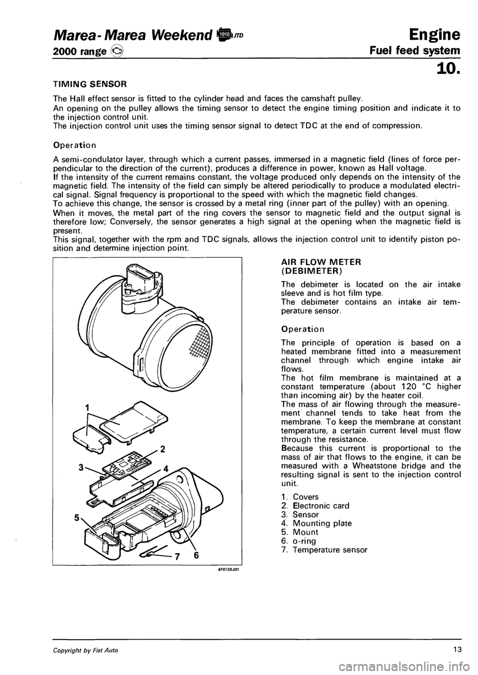
AIR FLOW METER
(DEBIMETER)
The debimeter is located on the air intake
sleeve and is hot film type.
The debimeter contains an intake air tem
perature sensor.
Operation
The principle of operation is based on a
heated membrane fitted into a measurement
channel through which engine intake air
flows.
The hot film membrane is maintained at a
constant temperature (about 120 °C higher
than incoming air) by the heater coil.
The mass of air flowing through the measure
ment channel tends to take heat from the
membrane. To keep the membrane at constant
temperature, a certain current level must flow
through the resistance.
Because this current is proportional to the
mass of air that flows to the engine, it can be
measured with a Wheatstone bridge and the
resulting signal is sent to the injection control
unit.
1. Covers
2. Electronic card
3. Sensor
4. Mounting plate
5. Mount
6. o-ring
7. Temperature sensor
Copyright by Fiat Auto 13
Page 101 of 330
Marea- Marea Weekend 9™
2000 range (§)
4F015XJ03
Engine
Fuel feed system
ijo.
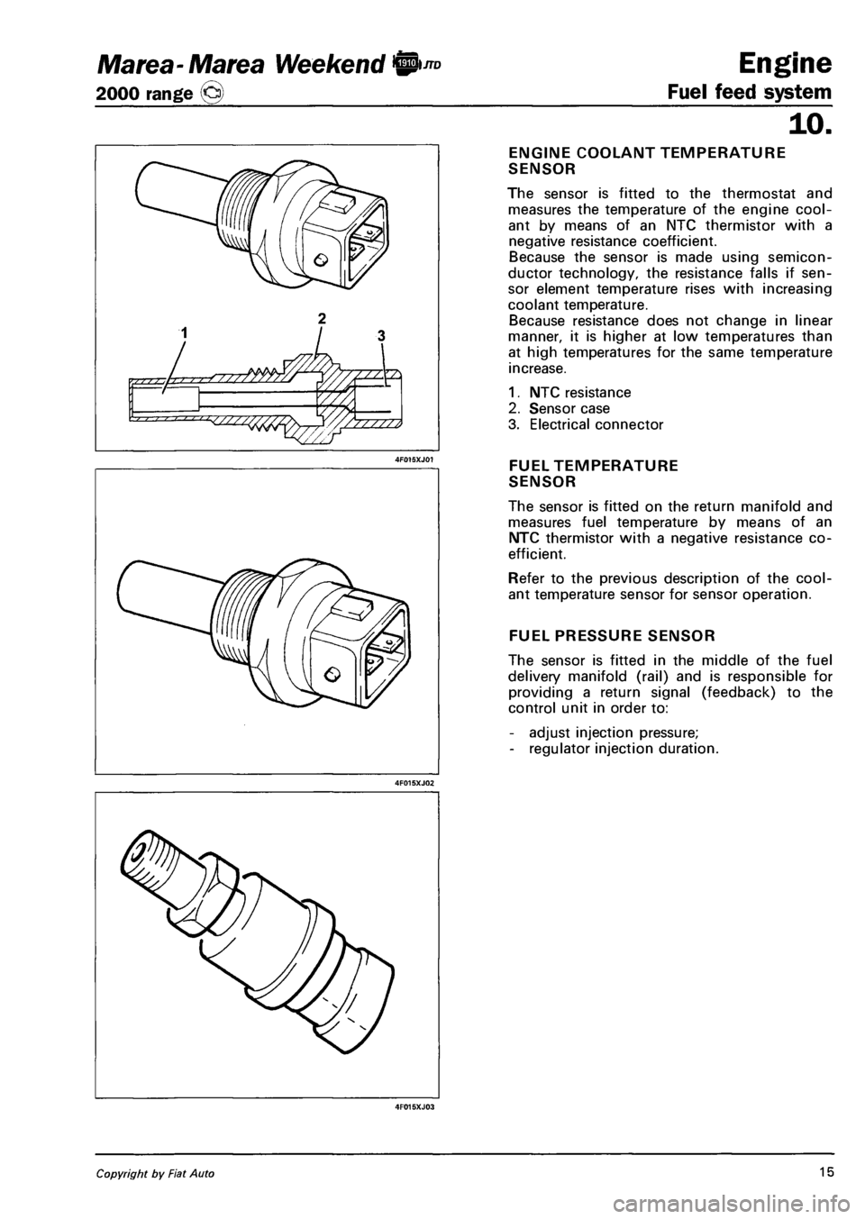
ENGINE COOLANT TEMPERATURE
SENSOR
The sensor is fitted to the thermostat and
measures the temperature of the engine cool
ant by means of an NTC thermistor with a
negative resistance coefficient.
Because the sensor is made using semicon
ductor technology, the resistance falls if sen
sor element temperature rises with increasing
coolant temperature.
Because resistance does not change in linear
manner, it is higher at low temperatures than
at high temperatures for the same temperature
increase.
1. NTC resistance
2. Sensor case
3. Electrical connector
FUEL TEMPERATURE
SENSOR
The sensor is fitted on the return manifold and
measures fuel temperature by means of an
NTC thermistor with a negative resistance co
efficient.
Refer to the previous description of the cool
ant temperature sensor for sensor operation.
FUEL PRESSURE SENSOR
The sensor is fitted in the middle of the fuel
delivery manifold (rail) and is responsible for
providing a return signal (feedback) to the
control unit in order to:
- adjust injection pressure;
- regulator injection duration.
Copyright by Fiat Auto 15
Page 104 of 330
Engine
Fuel feed system
JTD Marea- Marea Weekend 0
2000 range ©
10.
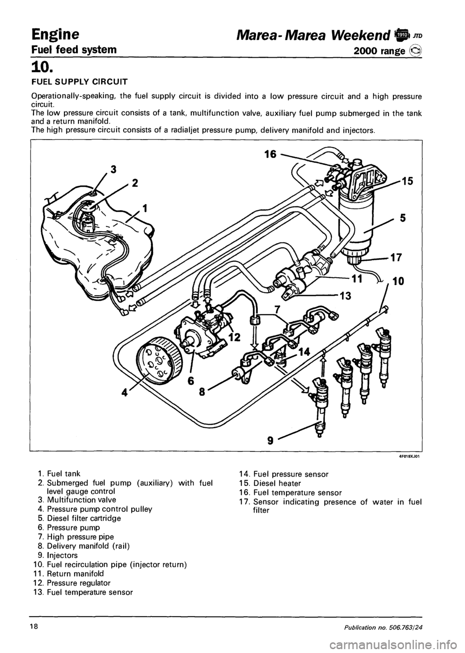
FUEL SUPPLY CIRCUIT
Operationally-speaking, the fuel supply circuit is divided into a low pressure circuit and a high pressure
circuit.
The low pressure circuit consists of a tank, multifunction valve, auxiliary fuel pump submerged in the tank
and a return manifold.
The high pressure circuit consists of a radialjet pressure pump, delivery manifold and injectors.
1. Fuel tank
2. Submerged fuel pump (auxiliary) with fuel
level gauge control
3. Multifunction valve
4. Pressure pump control pulley
5. Diesel filter cartridge
6. Pressure pump
7. High pressure pipe
8. Delivery manifold (rail)
9. Injectors
10. Fuel recirculation pipe (injector return)
11. Return manifold
12. Pressure regulator
13. Fuel temperature sensor
14. Fuel pressure sensor
15. Diesel heater
16. Fuel temperature sensor
17. Sensor indicating presence of water in fuel
filter
18 Publication no. 506.763/24
Page 105 of 330
Marea- Marea Weekend 9 ™
2000 range (Q)
4F019XJ01
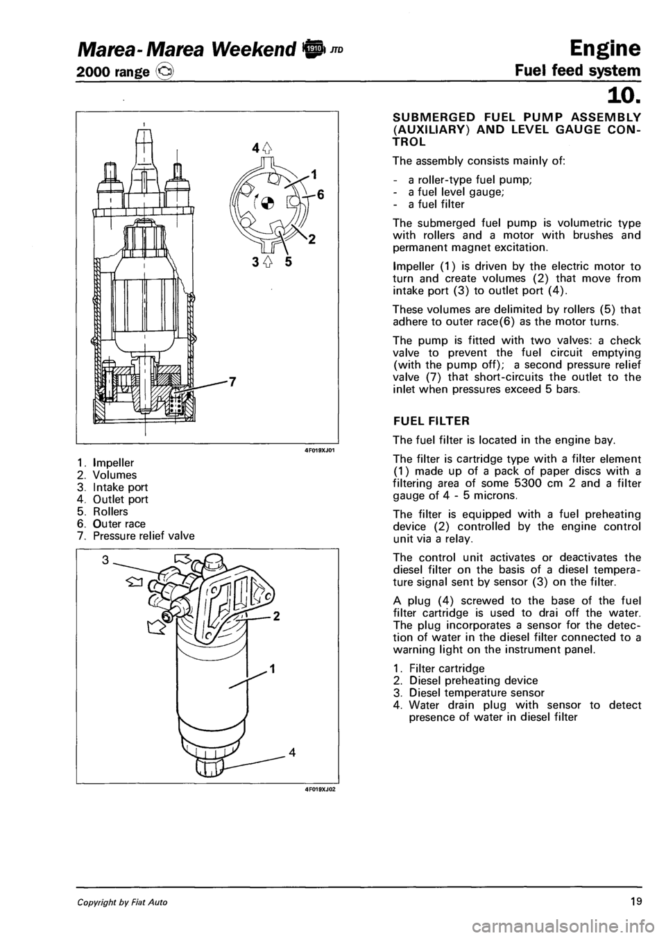
1. Impeller
2. Volumes
3. Intake port
4. Outlet port
5. Rollers
6. Outer race
7. Pressure relief valve
4F019XJ02
Engine
Fuel feed system
10.
SUBMERGED FUEL PUMP ASSEMBLY
(AUXILIARY) AND LEVEL GAUGE CON
TROL
The assembly consists mainly of:
- a roller-type fuel pump;
- a fuel level gauge;
- a fuel filter
The submerged fuel pump is volumetric type
with rollers and a motor with brushes and
permanent magnet excitation.
Impeller (1) is driven by the electric motor to
turn and create volumes (2) that move from
intake port (3) to outlet port (4).
These volumes are delimited by rollers (5) that
adhere to outer race(6) as the motor turns.
The pump is fitted with two valves: a check
valve to prevent the fuel circuit emptying
(with the pump off); a second pressure relief
valve (7) that short-circuits the outlet to the
inlet when pressures exceed 5 bars.
FUEL FILTER
The fuel filter is located in the engine bay.
The filter is cartridge type with a filter element
(1) made up of a pack of paper discs with a
filtering area of some 5300 cm 2 and a filter
gauge of 4 - 5 microns.
The filter is equipped with a fuel preheating
device (2) controlled by the engine control
unit via a relay.
The control unit activates or deactivates the
diesel filter on the basis of a diesel tempera
ture signal sent by sensor (3) on the filter.
A plug (4) screwed to the base of the fuel
filter cartridge is used to drai off the water.
The plug incorporates a sensor for the detec
tion of water in the diesel filter connected to a
warning light on the instrument panel.
1. Filter cartridge
2. Diesel preheating device
3. Diesel temperature sensor
4. Water drain plug with sensor to detect
presence of water in diesel filter
Copyright by Fiat Auto 19
Page 234 of 330
Electrical system
Component location
Marea-Marea Weekend
2000 range ©
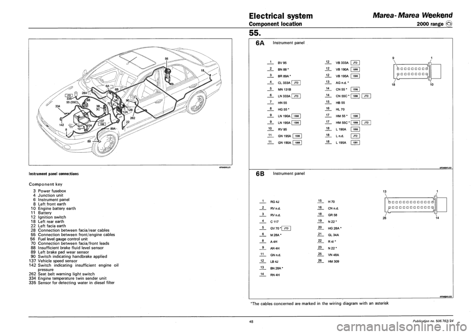
INSTRUMENT PANEL CONNECTIONS
Component key
3
4
6
8
10
11
12
18
22
28
55
56
70
88
89
90
Power fusebox
Junction unit
Instrument panel
Left front earth
Engine battery earth
Battery
Ignition switch
Left rear earth
Left facia earth
Connection between facia/rear cables
Connection between front/engine cables
Fuel level gauge control unit
Connection between facia/front leads
Insufficient brake fluid level sensor
Left brake pad wear sensor
Switch indicating handbrake applied
137 Vehicle speed sensor
142 Switch indicating insufficient engine oil
pressure
262 Seat belt warning light switch
334 Engine temperature twin sender unit
335 Sensor for detecting water in diesel filter
55.
Instrument panel
1
2
3
4
5
6
7
8
9
9
10
11
11
F3V95
BN 88*
BR 89A*
CL 333A I JTD
MN 131B
LN 333A | JTD
HN55
HG55*
LN 190A 1998
LN 195A | 1596
RV95
GN 195A 1596
GN 190A 1998
12
12
12
13
14
14
15
16
17
17
18
18
18
VB 333A JTD
VB 190A 1998
1596
1998
VB 195A | 1596
AG n.d. *
CN 55 *
CN 55C *
HB 55
HL70
HM 55*
HM 55C * |
L190A
Ln.d.
L195A
•••••••
•••••••
18 10
JTD
1596
1998
1998
JTD
1581
6B Instrument panel
13
1
2
3
4
5
6
8
9
11
12
13
14
RG4J
RV n.d.
RV n.d.
C117
GV 70 *| JTD
M28A*
A4H
AN4H
GN n.d.
LB4J
BN 28A *
RN 4H
15
16
18
19
20
21
22
23
25
26
H70
CN n.d.
GR 58
N22*
HG 28A *
GL34A
R4I *
N22*
VN48A
HM309
•••••••••••
•••••••••••
26 14
4F048ML03
The cables concerned are marked in the wiring diagram with an asterisk
48 Publication no. 506.763/24
Page 236 of 330
Electrical equipment
Component location
Marea-Marea Weekend
2000 range ®
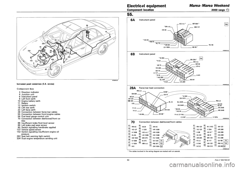
Instrument panel connections (C.A. version)
Component key
3 Direction indicator
4 Junction unit
6 Instrument panel
8 Left front earth
10 Engine battery earth
11 Battery
12 Ignition switch
18 Left rear earth
22 Left facia earth
28 Connection between facia/rear cables
55 Connection between front/engine cables
56 Fuel level gauge control unit
70 Connection between dashborad/front ca
bles
88 Insufficient brake fluid level sensor
89 Left brake pad wear sensor
90 Switch signalling handbrake applied
137 Vehicle speed sensor
142 Switch signalling insufficient engine oil
pressure
262 Seat belt warning light switch
334 Dual engine temperature sending unit
55.
6A Instrument panel
AG n.d. * BR 89A *
MN 131
HG 55 *HM55
RV95
6B Instrument panel
GL34A
*N22
AN4H
28A Facia/rear lead connection
RN n.d
GN 309
NZ22
AR120
MB34A
V70
RN n.d.
V107A
70 Connection between dashborad/front cables
A1 B1 C1 — RN4C — M29 — AN4C A2 B2 C2 — VG127 — V328 — HR100B A3 B3 C3 — H100B — AG n.d. * — HN 100B A4 B4 C4 — HL6A — LN 100B — HG 100B A5 B5 C5 — CB 100A — BN 375 — HV 100B A6 B6 C7 | — S100B — B375 — GV335 JTD A7 B8 C8 • — V 100A — MN n.d. — RB 307 I TAXI A8 C8 — N 8 — GN 195A ^
A1 — RN120 A2 — VG120 A3 — H6B A4 — HL120 A5 — CB28A A6 — Rn.d. A7 — A34A A8 — N312
B1 — M 310C B2 — V28A B3 — AG 41* B4 — AB4I B5 — BN120 B6 — B117 B7 — AN 120 B8
C1 — AN 120 C2 — HR28B C3 — HN28B C4 — HG28B C5 — HV28B C7 — GV6B C8 JTD
C8 RB312 TAXI
RN315 — GN6BCS
4F060ML05
* The cables involved in the wiring diagram are marked with an asterisk.
50 Print n° 506.763/23
Page 238 of 330
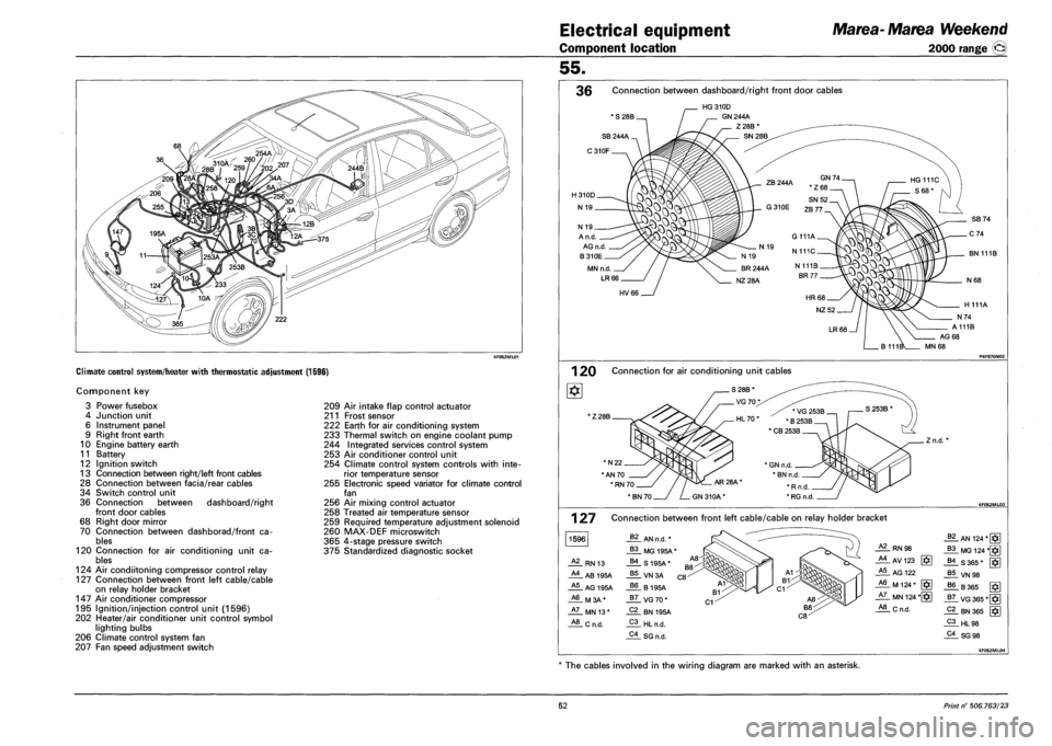
Electrical equipment
Component location
Marea- Marea Weekend
2000 range ®
Climate control system/heater with thermostatic adjustment (1596)
Component key
3 Power fusebox
4 Junction unit
6 Instrument panel
9 Right front earth
10 Engine battery earth
11 Battery
12 Ignition switch
13 Connection between right/left front cables
28 Connection between facia/rear cables
34 Switch control unit
36 Connection between dashboard/right
front door cables
68 Right door mirror
70 Connection between dashborad/front ca
bles
120 Connection for air conditioning unit ca
bles
124 Air condiitoning compressor control relay
127 Connection between front left cable/cable
on relay holder bracket
147 Air conditioner compressor
195 Ignition/injection control unit (1596)
202 Heater/air conditioner unit control symbol
lighting bulbs
206 Climate control system fan
207 Fan speed adjustment switch
209 Air intake flap control actuator
211 Frost sensor
222 Earth for air conditioning system
233 Thermal switch on engine coolant pump
244 Integrated services control system
253 Air conditioner control unit
254 Climate control system controls with inte
rior temperature sensor
255 Electronic speed variator for climate control
fan
256 Air mixing control actuator
258 Treated air temperature sensor
259 Required temperature adjustment solenoid
260 MAX-DEF microswitch
365 4-stage pressure switch
375 Standardized diagnostic socket
55.
36 Connection between dashboard/right front door cables
* S 28B.
HG310D
GN 244A
Z28B
N 19 _
A n.d.
AG n.d
B310E
MN n.d.
LR66
BN 111B
HV66
AG 68
MN 68
1 20 Connection for air conditioning unit cables
1Z 28B.
*N22.
"AN 70
' RN 70.
. Z n.d.
127
1596
Connection between front left cable/cable on relay holder bracket
62 AN n.d. *
B3 MG 195A*
A2 RN 13 B4 S195A*
A4 AB 195A B5 VN3A
A5 AG 195A B6 B195A
A6 M3A* B7 VG70*
A7 MN 13* C2 BN 195A
A8 Cn.d. C3 HL n.d.
C4 SG n.d.
RN 98
_AlAV123 g*]
A5 AG 122
_A6_ M 124 * [§]
JiL MN 124 *[§]
_*!L C n.d.
_§?_ AN 124*[§]
_B3_MG 124 *§]
-US 365* [$]
J*!LVN98
J?6. B 365 [ffi
_g7_ VG 365*[
_Pi_ HL98
_?i_SG 98
The cables involved in the wiring diagram are marked with an asterisk.
52 Print n° 506.763/23
Page 240 of 330
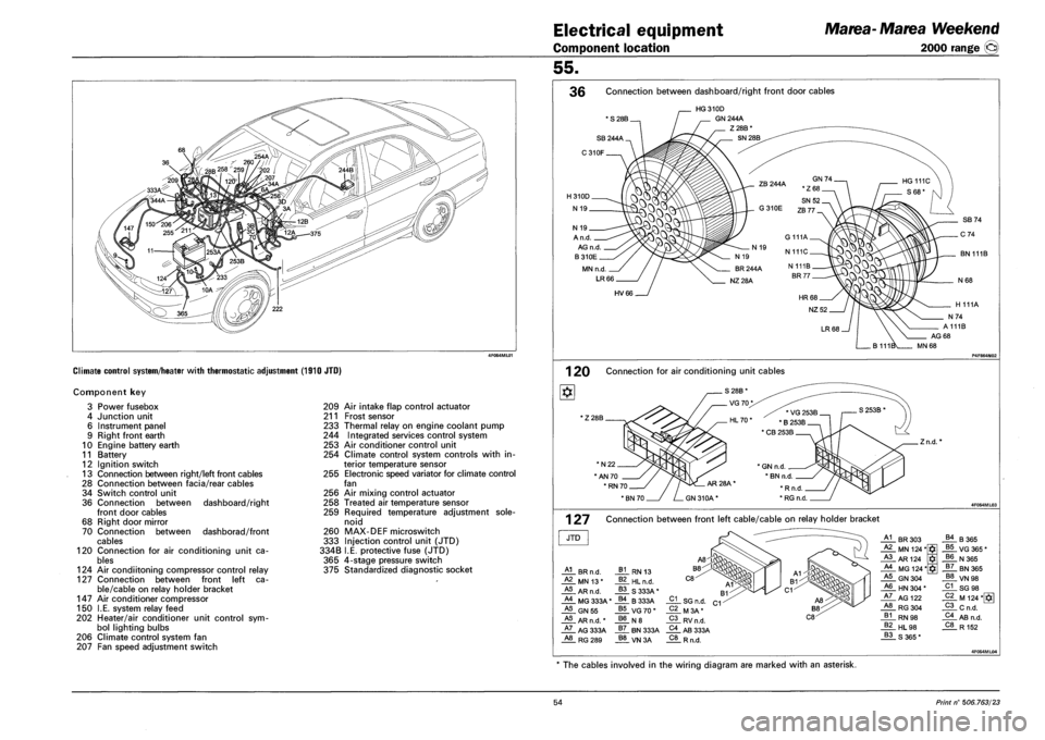
Electrical equipment
Component location
Marea- Marea Weekend
2000 range ®
Climate control system/heater with thermostatic adjustment (1910 JTO)
Component key
Power fusebox
Junction unit
Instrument panel
Right front earth
Engine battery earth
Battery
Ignition switch
Connection between right/left front cables
Connection between facia/rear cables
Switch control unit
Connection between
front door cables
Right door mirror
Connection between
cables
Connection for air conditioning unit ca
bles
124 Air condiitoning compressor control relay
127 Connection between front left ca
ble/cable on relay holder bracket
Air conditioner compressor
I.E. system relay feed
Heater/air conditioner unit control sym
bol lighting bulbs
Climate control system fan
Fan speed adjustment switch
3
4
6
9
10
11
12
13
28
34
36
68
70
120
147
150
202
206
207
dashboard/right
dashborad/front
209 Air intake flap control actuator
211 Frost sensor
233 Thermal relay on engine coolant pump
244 Integrated services control system
253 Air conditioner control unit
254 Climate control system controls with in
terior temperature sensor
255 Electronic speed variator for climate control
fan
256 Air mixing control actuator
258 Treated air temperature sensor
259 Required temperature adjustment sole
noid
260 MAX-DEF microswitch
333 Injection control unit (JTD)
334B I.E. protective fuse (JTD)
365 4-stage pressure switch
375 Standardized diagnostic socket
55.
36 Connection between dashboard/right front door cables
' S 28B.
HG310D
GN 244A
Z28B*
SN 28B
A n.d.
AG n.d.
B310E
MN n.d
LR66
BN 111B
HV66
1 20 Connection for air conditioning unit cables
' Z 28B
*N22.
"AN 70
.Zn.d.
1 27 Connection between front left cable/cable on relay holder bracket
JTD
HL BR n.d.
_ALMNI3*
HL AR n.d.
HL MG 333A'
HL GN55
HL AR n.d. *
HL AG 333A A8 RG289
_A1_ BR 303 B4 B365 A2 MN 124* $ B5 VG 365 * A3 AR124 B6 N365 A4 MG 124* $ B7 BN 365 A5 GN 304 B8 VN 98 A6 HN 304 * C1 SG 98 A7 AG 122 C2 M 124*[*g A8 RG304 C3 Cn.d. B1 RN 98 C4 AB n.d. B2 HL 98 C8 R152 B3 S365*
The cables involved in the wiring diagram are marked with an asterisk.
54 Print n° 506.763/23