engine coolant FIAT MAREA 2001 1.G Owner's Manual
[x] Cancel search | Manufacturer: FIAT, Model Year: 2001, Model line: MAREA, Model: FIAT MAREA 2001 1.GPages: 330
Page 145 of 330
Marea- Marea Weekend
2000 range ©
Electrical equipment
Control module
55.
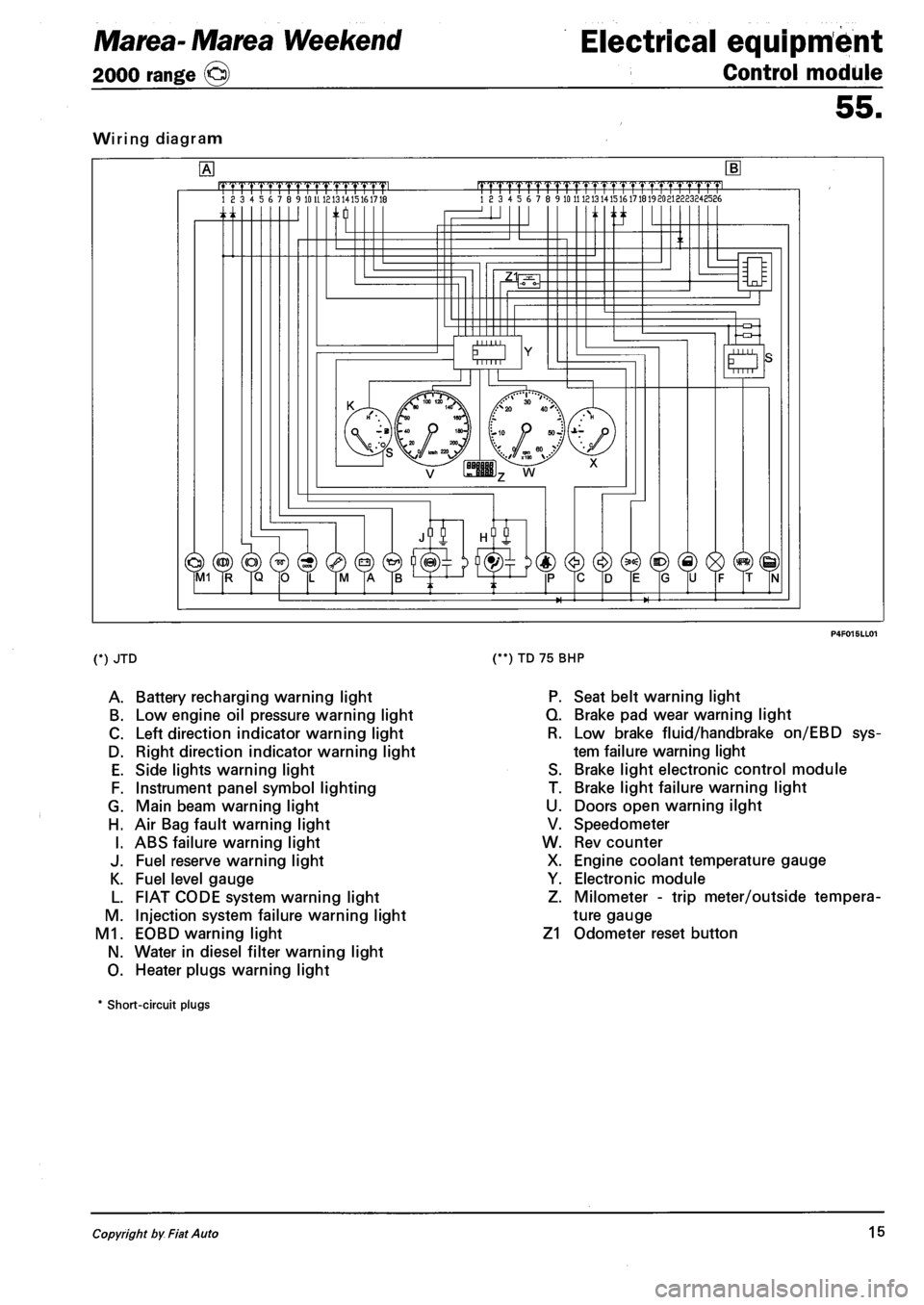
Wiring diagram
.mrmmmL 18 3 4 5 6 7 8 9 10 U 1213 1415161718 |TTTTrTrrrrTTTTT1.TTTTT1pmL 18 3 4 5 6 7 8 9 10 11 121314151617181920213223248586
n ti
O Mill
(*) JTD
A. Battery recharging warning light
B. Low engine oil pressure warning light
C. Left direction indicator warning light
D. Right direction indicator warning light
E. Side lights warning light
F. Instrument panel symbol lighting
G. Main beam warning light
H. Air Bag fault warning light
I. ABS failure warning light
J. Fuel reserve warning light
K. Fuel level gauge
L. FIAT CODE system warning light
M. Injection system failure warning light
M1. EOBD warning light
N. Water in diesel filter warning light
O. Heater plugs warning light
(**) TD 75 BHP
P. Seat belt warning light
Q. Brake pad wear warning light
R. Low brake fluid/handbrake on/EBD sys
tem failure warning light
S. Brake light electronic control module
T. Brake light failure warning light
U. Doors open warning ilght
V. Speedometer
W. Rev counter
X. Engine coolant temperature gauge
Y. Electronic module
Z. Milometer - trip meter/outside tempera
ture gauge
Z1 Odometer reset button
* Short-circuit plugs
Copyright by Fiat Auto 15
Page 146 of 330
Electrical equipment
Instrument panel
Marea- Marea Weekend
2000 range ©
55.
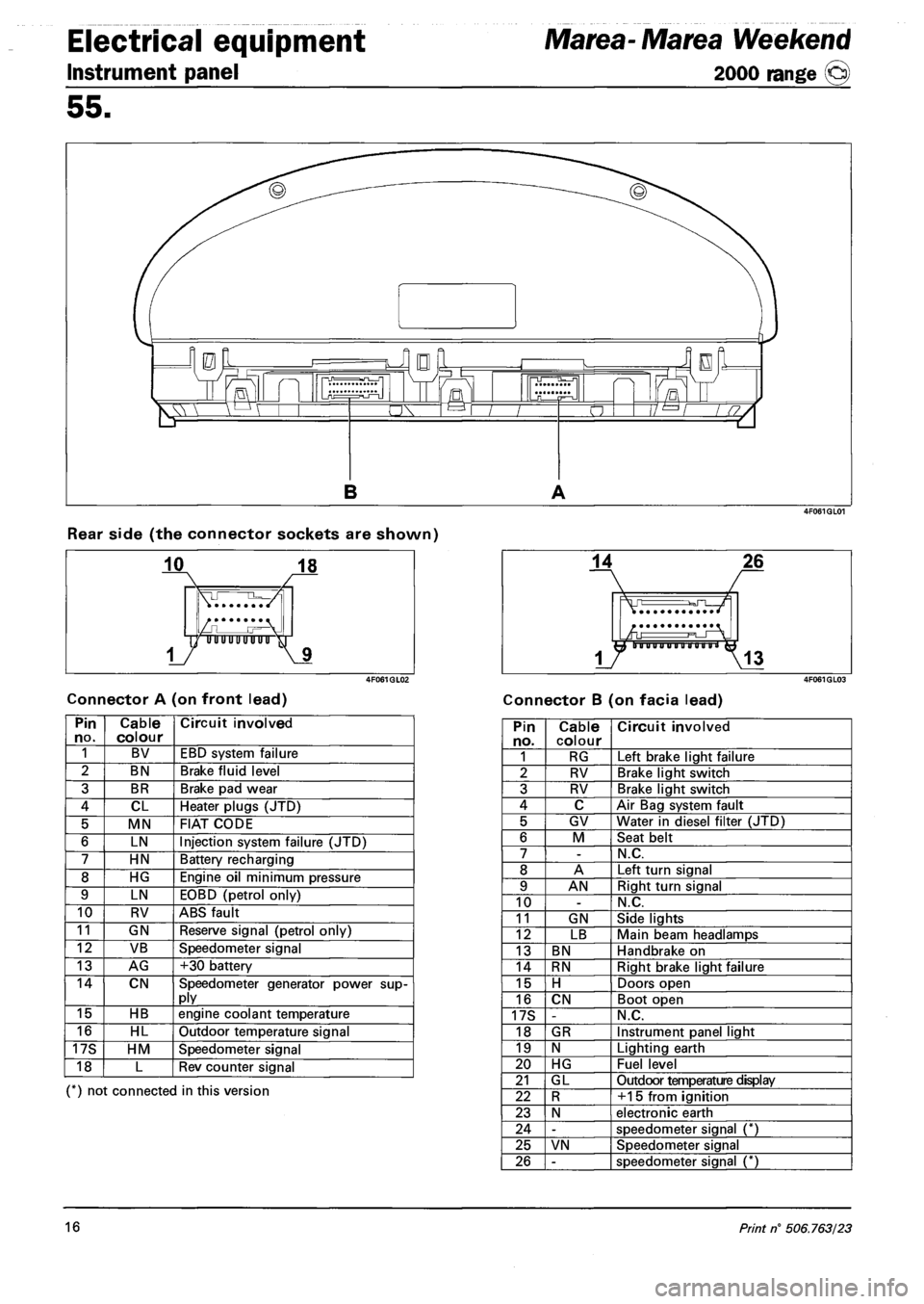
Rear side (the connector sockets are shown)
Connector A (on front lead) Connector B (on facia lead)
Pin no. Cable colour Circuit involved
1 BV EBD system failure
2 BN Brake fluid level
3 BR Brake pad wear
4 CL Heater plugs (JTD)
5 MN FIAT CODE
6 LN Injection system failure (JTD)
7 HN Battery recharging
8 HG Engine oil minimum pressure
9 LN EOBD (petrol only)
10 RV ABS fault
11 GN Reserve signal (petrol only)
12 VB Speedometer signal
13 AG +30 battery
14 CN Speedometer generator power supply
15 HB engine coolant temperature
16 HL Outdoor temperature signal
17S HM Speedometer signal
18 L Rev counter signal
(*) not connected in this version
Pin no. Cable colour Circuit involved
1 RG Left brake light failure
2 RV Brake light switch
3 RV Brake light switch
4 C Air Bag system fault
5 GV Water in diesel filter (JTD)
6 M Seat belt
7 -N.C.
8 A Left turn signal
9 AN Right turn signal
10 -N.C.
11 GN Side lights
12 LB Main beam headlamps
13 BN Handbrake on
14 RN Right brake light failure
15 H Doors open
16 CN Boot open
17S -N.C.
18 GR Instrument panel light
19 N Lighting earth
20 HG Fuel level
21 GL Outdoor temperature display
22 R +15 from ignition
23 N electronic earth
24 -speedometer signal (*)
25 VN Speedometer signal
26 -speedometer signal (*)
16 Print n° 506.763/23
Page 147 of 330
Marea- Marea Weekend Electrical equipment
2000 range (Q) Control module
55.
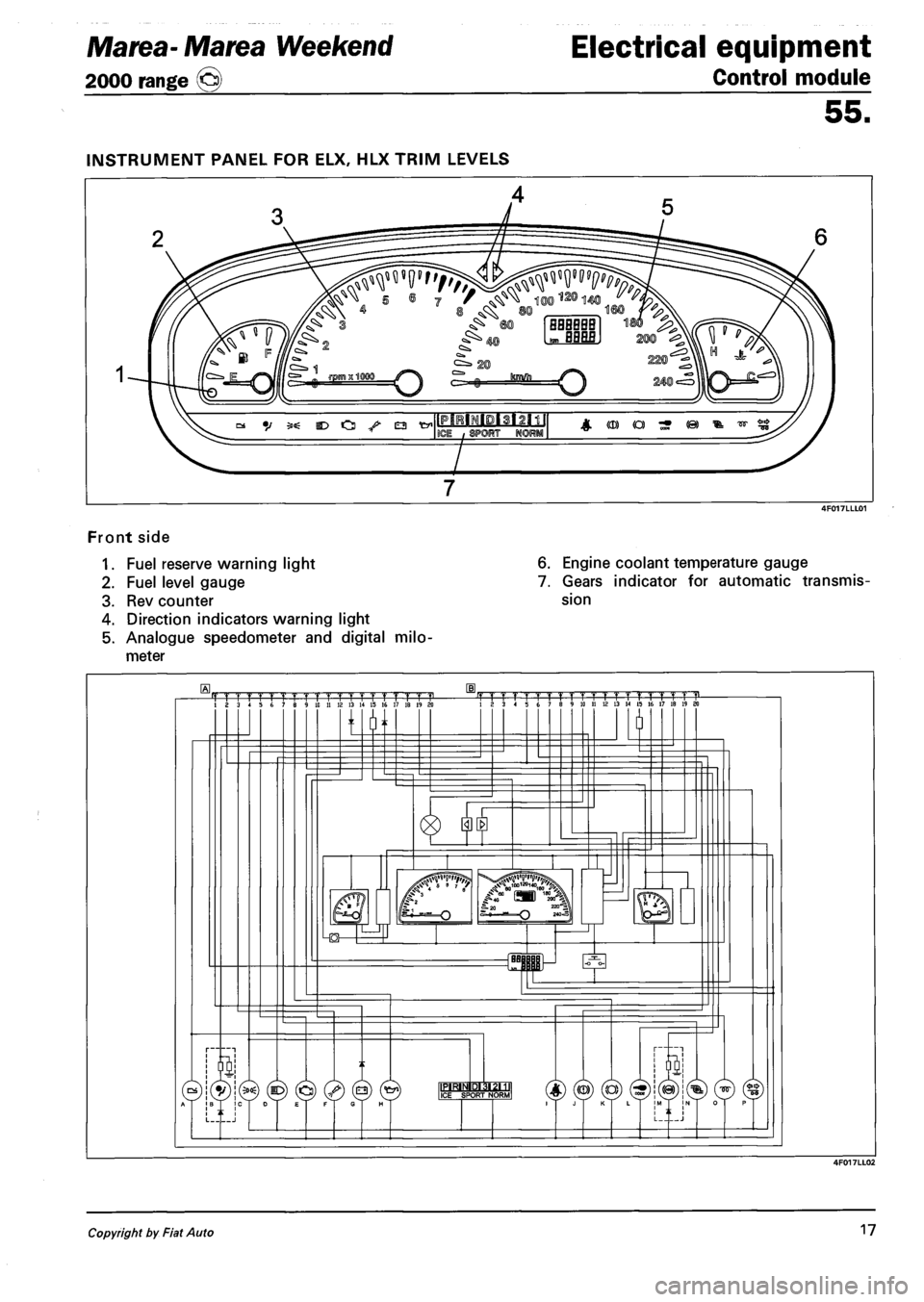
Front side
1. Fuel reserve warning light
2. Fuel level gauge
3. Rev counter
4. Direction indicators warning light
5. Analogue speedometer and digital milo
meter
6. Engine coolant temperature gauge
7. Gears indicator for automatic transmis
sion
Copyright by Fiat Auto 17
Page 187 of 330
Marea- Marea Weekend
2000 range ©
Electrical equipment
Wiring diagrams
55.
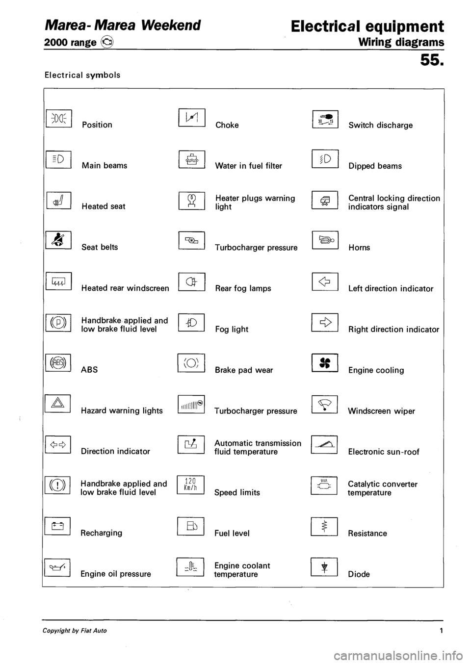
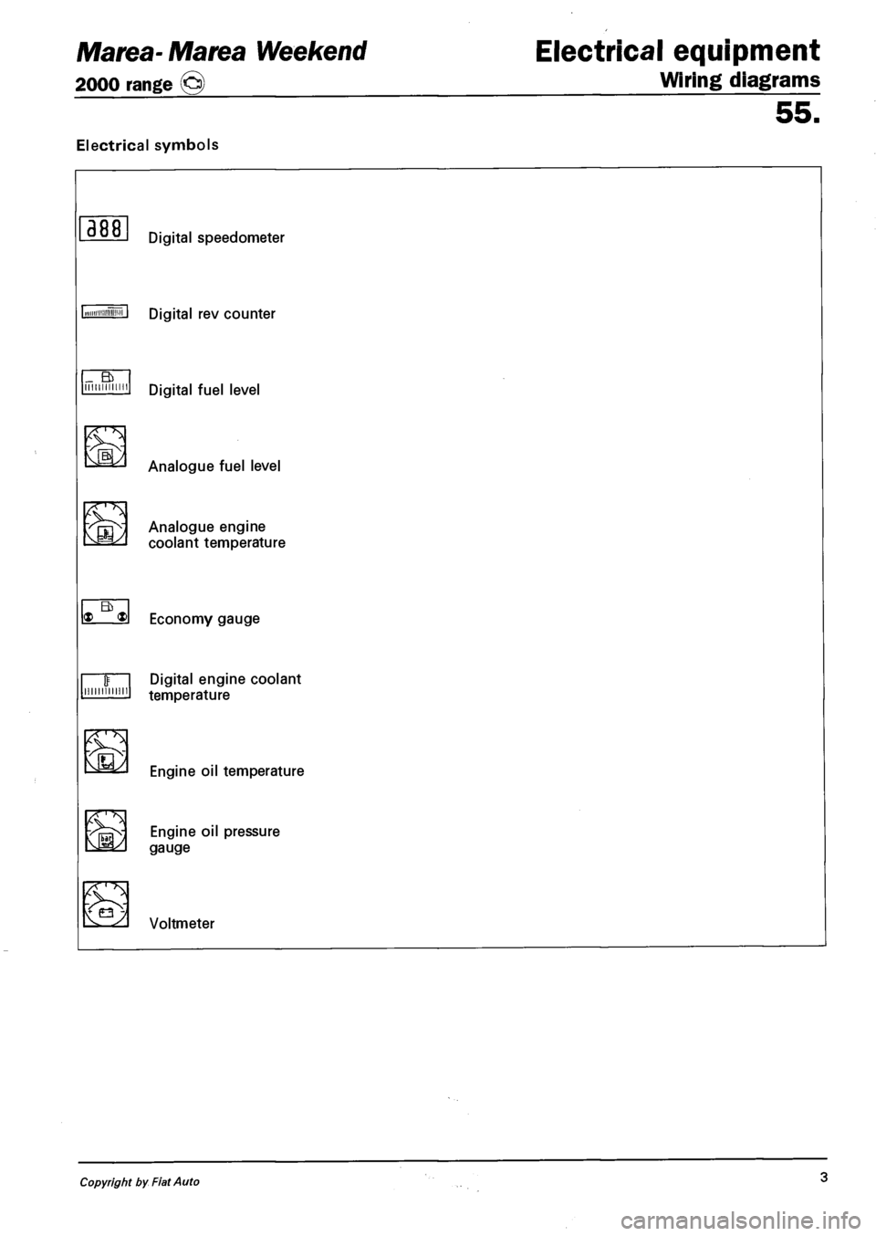
Electrical symbols
M
Lt3
Position
Main beams
Heated seat
Seat belts
Heated rear windscreen
Handbrake applied and
low brake fluid level
ABS
Hazard warning lights
Direction indicator
Handbrake applied and
low brake fluid level
Recharging
Engine oil pressure
IX!
(O)
Hum®
120 Km/h
Choke
Water in fuel filter
Heater plugs warning
light
Turbocharger pressure
Rear fog lamps
Fog light
Brake pad wear
Turbocharger pressure
Automatic transmission
fluid temperature
Speed limits
Fuel level
Engine coolant
temperature
to
Switch discharge
Dipped beams
Central locking direction
indicators signal
Horns
Left direction indicator
Right direction indicator
Engine cooling
Windscreen wiper
Electronic sun-roof
Catalytic converter
temperature
Resistance
Diode
Copyright by Fiat Auto 1
Page 189 of 330
Marea- Marea Weekend
2000 range ©
Electrical equipment
Wiring diagrams
Electrical symbols
55.
388
_ a IIIIIIIIIIMI
'
Eb * ®
minium
Ev3
'
Digital rev counter
Digital fuel level
Analogue fuel level
Analogue engine
coolant temperature
Economy gauge
Digital engine coolant
temperature
Engine oil temperature
vfOSv EN9|NE °'l pressure M35^ gauge
iE2 Voltmeter
Copyright by Fiat Auto 3
Page 238 of 330
Electrical equipment
Component location
Marea- Marea Weekend
2000 range ®
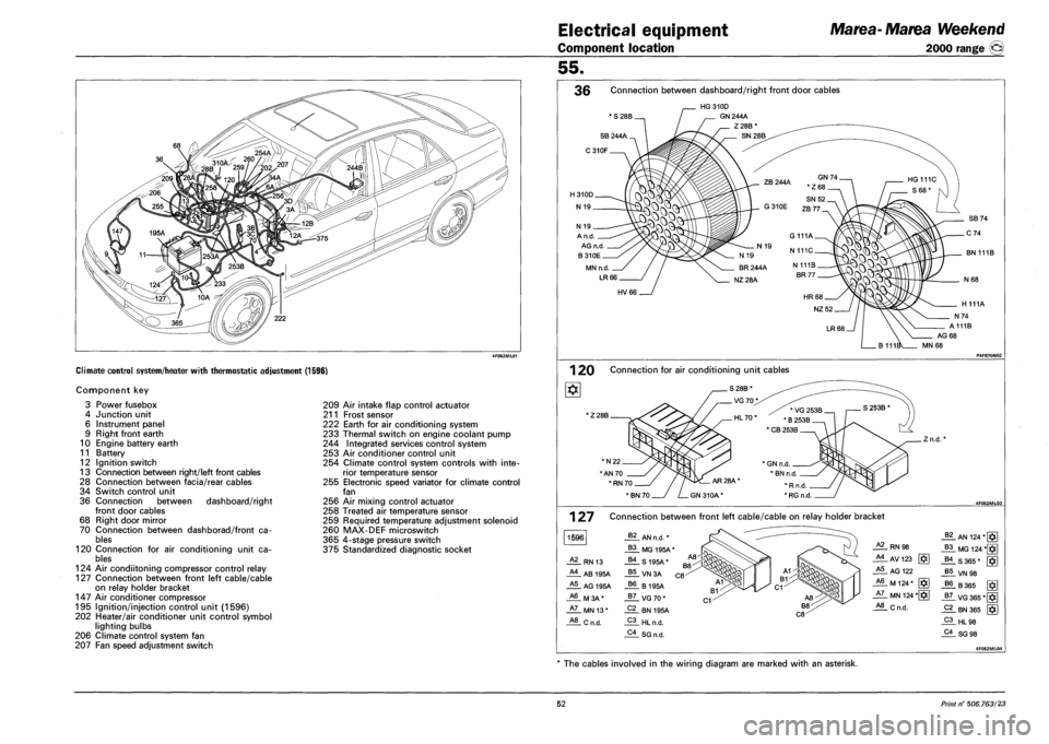
Climate control system/heater with thermostatic adjustment (1596)
Component key
3 Power fusebox
4 Junction unit
6 Instrument panel
9 Right front earth
10 Engine battery earth
11 Battery
12 Ignition switch
13 Connection between right/left front cables
28 Connection between facia/rear cables
34 Switch control unit
36 Connection between dashboard/right
front door cables
68 Right door mirror
70 Connection between dashborad/front ca
bles
120 Connection for air conditioning unit ca
bles
124 Air condiitoning compressor control relay
127 Connection between front left cable/cable
on relay holder bracket
147 Air conditioner compressor
195 Ignition/injection control unit (1596)
202 Heater/air conditioner unit control symbol
lighting bulbs
206 Climate control system fan
207 Fan speed adjustment switch
209 Air intake flap control actuator
211 Frost sensor
222 Earth for air conditioning system
233 Thermal switch on engine coolant pump
244 Integrated services control system
253 Air conditioner control unit
254 Climate control system controls with inte
rior temperature sensor
255 Electronic speed variator for climate control
fan
256 Air mixing control actuator
258 Treated air temperature sensor
259 Required temperature adjustment solenoid
260 MAX-DEF microswitch
365 4-stage pressure switch
375 Standardized diagnostic socket
55.
36 Connection between dashboard/right front door cables
* S 28B.
HG310D
GN 244A
Z28B
N 19 _
A n.d.
AG n.d
B310E
MN n.d.
LR66
BN 111B
HV66
AG 68
MN 68
1 20 Connection for air conditioning unit cables
1Z 28B.
*N22.
"AN 70
' RN 70.
. Z n.d.
127
1596
Connection between front left cable/cable on relay holder bracket
62 AN n.d. *
B3 MG 195A*
A2 RN 13 B4 S195A*
A4 AB 195A B5 VN3A
A5 AG 195A B6 B195A
A6 M3A* B7 VG70*
A7 MN 13* C2 BN 195A
A8 Cn.d. C3 HL n.d.
C4 SG n.d.
RN 98
_AlAV123 g*]
A5 AG 122
_A6_ M 124 * [§]
JiL MN 124 *[§]
_*!L C n.d.
_§?_ AN 124*[§]
_B3_MG 124 *§]
-US 365* [$]
J*!LVN98
J?6. B 365 [ffi
_g7_ VG 365*[
_Pi_ HL98
_?i_SG 98
The cables involved in the wiring diagram are marked with an asterisk.
52 Print n° 506.763/23
Page 240 of 330
Electrical equipment
Component location
Marea- Marea Weekend
2000 range ®
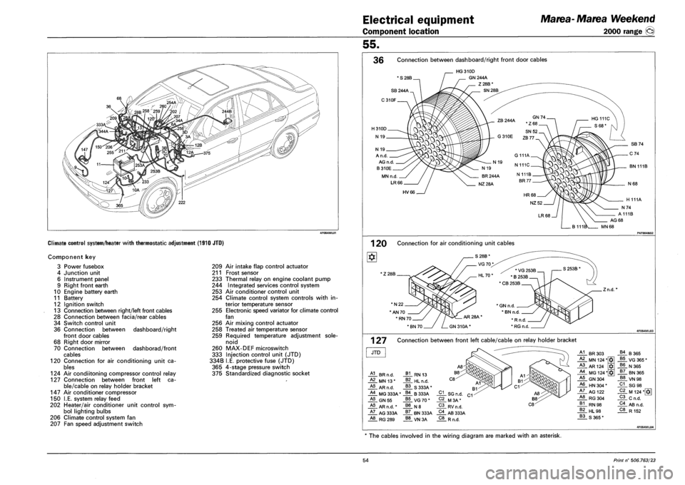
Climate control system/heater with thermostatic adjustment (1910 JTO)
Component key
Power fusebox
Junction unit
Instrument panel
Right front earth
Engine battery earth
Battery
Ignition switch
Connection between right/left front cables
Connection between facia/rear cables
Switch control unit
Connection between
front door cables
Right door mirror
Connection between
cables
Connection for air conditioning unit ca
bles
124 Air condiitoning compressor control relay
127 Connection between front left ca
ble/cable on relay holder bracket
Air conditioner compressor
I.E. system relay feed
Heater/air conditioner unit control sym
bol lighting bulbs
Climate control system fan
Fan speed adjustment switch
3
4
6
9
10
11
12
13
28
34
36
68
70
120
147
150
202
206
207
dashboard/right
dashborad/front
209 Air intake flap control actuator
211 Frost sensor
233 Thermal relay on engine coolant pump
244 Integrated services control system
253 Air conditioner control unit
254 Climate control system controls with in
terior temperature sensor
255 Electronic speed variator for climate control
fan
256 Air mixing control actuator
258 Treated air temperature sensor
259 Required temperature adjustment sole
noid
260 MAX-DEF microswitch
333 Injection control unit (JTD)
334B I.E. protective fuse (JTD)
365 4-stage pressure switch
375 Standardized diagnostic socket
55.
36 Connection between dashboard/right front door cables
' S 28B.
HG310D
GN 244A
Z28B*
SN 28B
A n.d.
AG n.d.
B310E
MN n.d
LR66
BN 111B
HV66
1 20 Connection for air conditioning unit cables
' Z 28B
*N22.
"AN 70
.Zn.d.
1 27 Connection between front left cable/cable on relay holder bracket
JTD
HL BR n.d.
_ALMNI3*
HL AR n.d.
HL MG 333A'
HL GN55
HL AR n.d. *
HL AG 333A A8 RG289
_A1_ BR 303 B4 B365 A2 MN 124* $ B5 VG 365 * A3 AR124 B6 N365 A4 MG 124* $ B7 BN 365 A5 GN 304 B8 VN 98 A6 HN 304 * C1 SG 98 A7 AG 122 C2 M 124*[*g A8 RG304 C3 Cn.d. B1 RN 98 C4 AB n.d. B2 HL 98 C8 R152 B3 S365*
The cables involved in the wiring diagram are marked with an asterisk.
54 Print n° 506.763/23