Ignition FIAT MAREA 2001 1.G Owner's Guide
[x] Cancel search | Manufacturer: FIAT, Model Year: 2001, Model line: MAREA, Model: FIAT MAREA 2001 1.GPages: 330
Page 163 of 330
Marea- Marea Weekend
2000 range @
Electrical system
Radio System
55.
OPERATION
ON/OFF
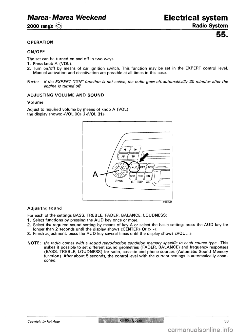
The set can be turned on and off in two ways.
1. Press knob A (VOL).
2. Turn on/off by means of car ignition switch. This function may be set in the EXPERT control level.
Manual activation and deactivation are possible at all times in this case.
Note: // the EXPERT "IGN" function is not active, the radio goes off automatically 20 minutes after the
engine is turned off.
ADJUSTING VOLUME AND SOUND
Volume
Adjust to required volume by means of knob A (VOL),
the display shows: «VOL 00» D «V0L 31».
Adjusitng sound
For each of the settings BASS, TREBLE, FADER, BALANCE, LOUDNESS:
1. Select functions by pressing the AUD key once or more.
2. Select the required sound setting by means of key A or select the basic setting: press the AUD key for
longer than 2 seconds until the display shows «CENTER» Or «- -«.
3. Finish adjustment: press the AUD key several times until the display shows «V0L ...».
NOTE: the radio comes with a sound reproduction condition memory specific to each source type.. This
makes it possible to set different sound geometries (FADER, BALANCE) and frequency responses
(BASS, TREBLE, LOUDNESS) for radio, cassette and phone sources (Automatic Sound Memory
function)..After about 5 seconds, the control level with the current settings is automatically aban
doned.
Copyright by Fiat Auto XII 00 - Update 33
4F033L01
Page 170 of 330
Electrical system
Radio System
55.
Scanning stored stations (SCAN)
The SCAN function allows automatic scanning of stored stations.
With IS LEARN OFF (EXP):
- short press: scan of all preset stations (keys 1-6) for all FM bands, or the 6 MW stations, or the 6 LW
stations
- press for more than 2 seconds: scan of all stations receivable on the FM band.
With IS LEARN ON (EXP):
- short press: scan of all preset stations (keys 1-6) for all FM bands
- press for longer than 2 seconds: scan IS LEARN
EXPERT CONTROL LEVEL
To make daily radio control as easy as possible, the supplementary control level (EXPERT) contains sev
eral settings that may be required once only or only occasionally.
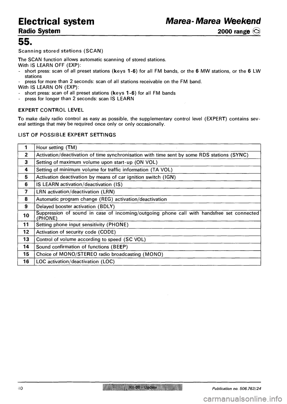
LIST OF POSSIBLE EXPERT SETTINGS
1 Hour setting (TM)
2 Activation/deactivation of time synchronisation with time sent by some RDS stations (SYNC)
3 Setting of maximum volume upon start-up (ON VOL)
4 Setting of minimum volume for traffic information (TA VOL)
5 Activation deactivation by means of car ignition switch (IGN)
6 IS LEARN activation/deactivation (IS)
7 LRN activation/deactivation (LRN)
8 Automatic program change (REG) activation/deactivation
9 Delayed booster activation (BDLY)
10 Suppression of sound in case of incoming/outgoing phone call with handsfree set connected
(PHONE)
11 Setting phone input sensitivity (PHONE)
12 Activation of security code (CODE)
13 Control of volume according to speed (SC VOL)
14 Sound confirmation of functions (BEEP)
15 Choice of MONO/STEREO radio broadcasting (MONO)
16 LOC activation/deactivation (LOC)
Marea- Marea Weekend
2000 range ©
40 XII-00 Update Publication no. 506.763/24
Page 172 of 330
Electrical system Marea-Marea Weekend
2000 range (§) Radio System
55.
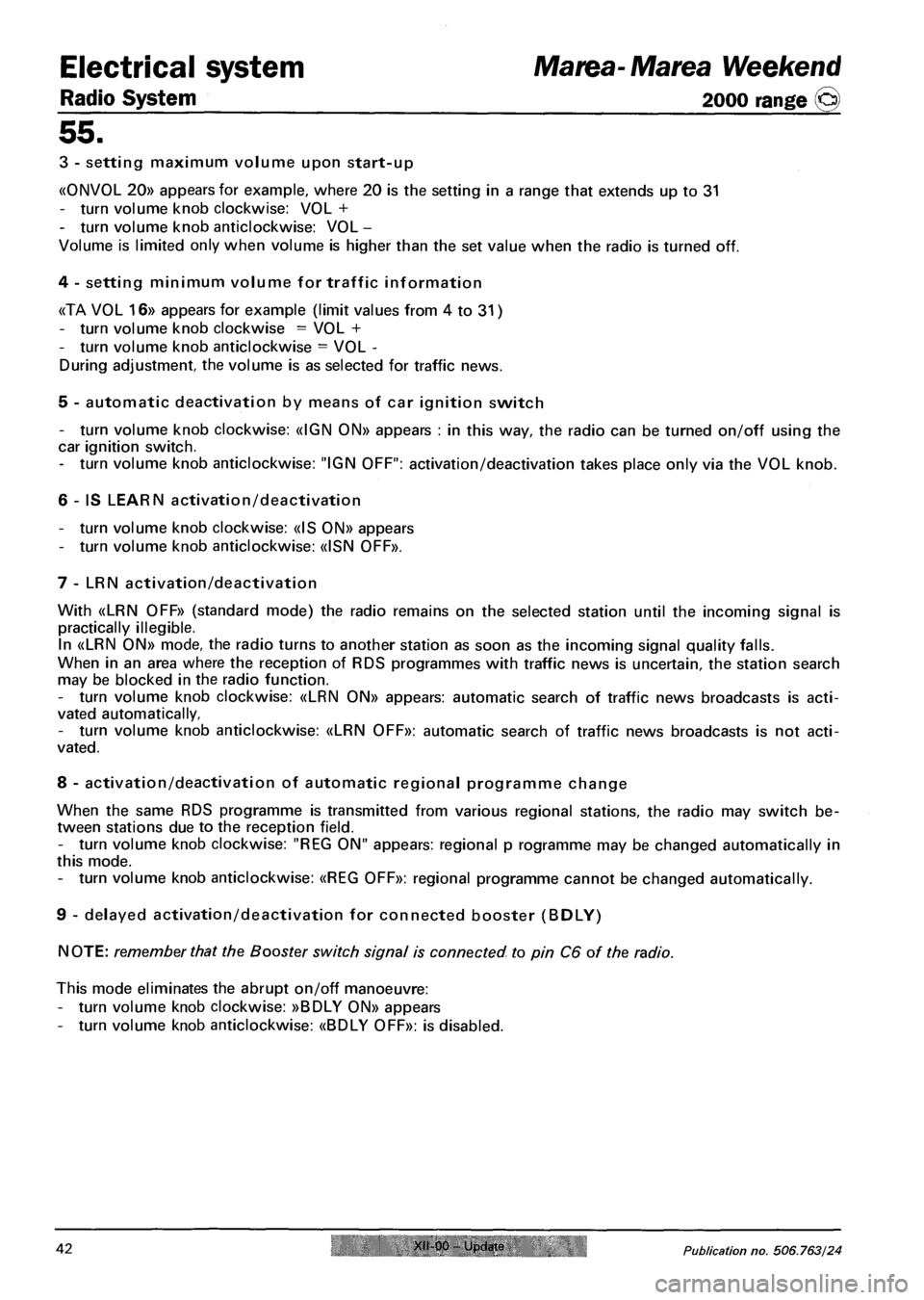
3 - setting maximum volume upon start-up
«0NV0L 20» appears for example, where 20 is the setting in a range that extends up to 31
- turn volume knob clockwise: VOL +
- turn volume knob anticlockwise: VOL -
Volume is limited only when volume is higher than the set value when the radio is turned off.
4 - setting minimum volume for traffic information
«TA VOL 16» appears for example (limit values from 4 to 31)
- turn volume knob clockwise = VOL +
- turn volume knob anticlockwise = VOL -
During adjustment, the volume is as selected for traffic news.
5 - automatic deactivation by means of car ignition switch
- turn volume knob clockwise: «IGN ON» appears : in this way, the radio can be turned on/off using the
car ignition switch.
- turn volume knob anticlockwise: "IGN OFF": activation/deactivation takes place only via the VOL knob.
6 - IS LEARN activation/deactivation
- turn volume knob clockwise: «IS 0N» appears
- turn volume knob anticlockwise: «ISN 0FF».
7 - LRN activation/deactivation
With «LRN OFF» (standard mode) the radio remains on the selected station until the incoming signal is
practically illegible.
In «LRN ON» mode, the radio turns to another station as soon as the incoming signal quality falls.
When in an area where the reception of RDS programmes with traffic news is uncertain, the station search
may be blocked in the radio function.
- turn volume knob clockwise: «LRN ON» appears: automatic search of traffic news broadcasts is acti
vated automatically,
- turn volume knob anticlockwise: «LRN OFF»: automatic search of traffic news broadcasts is not acti
vated.
8 - activation/deactivation of automatic regional programme change
When the same RDS programme is transmitted from various regional stations, the radio may switch be
tween stations due to the reception field.
- turn volume knob clockwise: "REG ON" appears: regional p rogramme may be changed automatically in
this mode.
- turn volume knob anticlockwise: «REG OFF»: regional programme cannot be changed automatically.
9 - delayed activation/deactivation for connected booster (BDLY)
NOTE: remember that the Booster switch signal is connected to pin C6 of the radio.
This mode eliminates the abrupt on/off manoeuvre:
- turn volume knob clockwise: »BDLY ON» appears
- turn volume knob anticlockwise: «BDLY OFF»: is disabled.
42 XII-00 Update Publication no. 506.763/24
Page 186 of 330
Marea-Marea Weekend Electrical equipment
2000 range (§) Wiring diagrams
55.
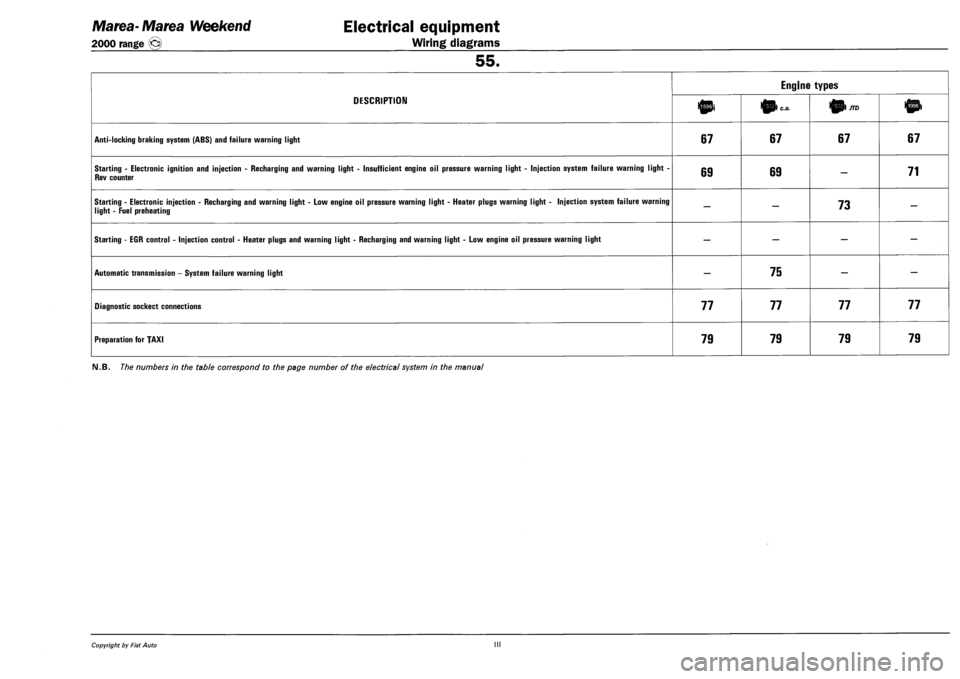
DESCRIPTION
Engine types
DESCRIPTION 10i 0) c.a. 01/70
ANTI-LOCKING BRAKING SYSTEM (ABS) AND FAILURE WARNING LIGHT 67 67 67 67
STARTING - ELECTRONIC IGNITION AND INJECTION - RECHARGING AND WARNING LIGHT - INSUFFICIENT ENGINE OIL PRESSURE WARNING LIGHT - INJECTION SYSTEM FAILURE WARNING LIGHT -
REV COUNTER 69 69 — 71
STARTING - ELECTRONIC INJECTION - RECHARGING AND WARNING LIGHT - LOW ENGINE OIL PRESSURE WARNING LIGHT - HEATER PLUGS WARNING LIGHT - INJECTION SYSTEM FAILURE WARNING
LIGHT - FUEL PREHEATING — — 73 —
STARTING - EGR CONTROL - INJECTION CONTROL - HEATER PLUGS AND WARNING LIGHT - RECHARGING AND WARNING LIGHT - LOW ENGINE OIL PRESSURE WARNING LIGHT — — — —
AUTOMATIC TRANSMISSION - SYSTEM FAILURE WARNING LIGHT — 75 — —
DIAGNOSTIC SOCKECT CONNECTIONS 77 77 77 77
PREPARATION FOR TAXI 79 79 79 79
FM.B. The numbers in the table correspond to the page number of the electrical system in the manual
Copyright by Fiat Auto III
Page 192 of 330
4F006ML01
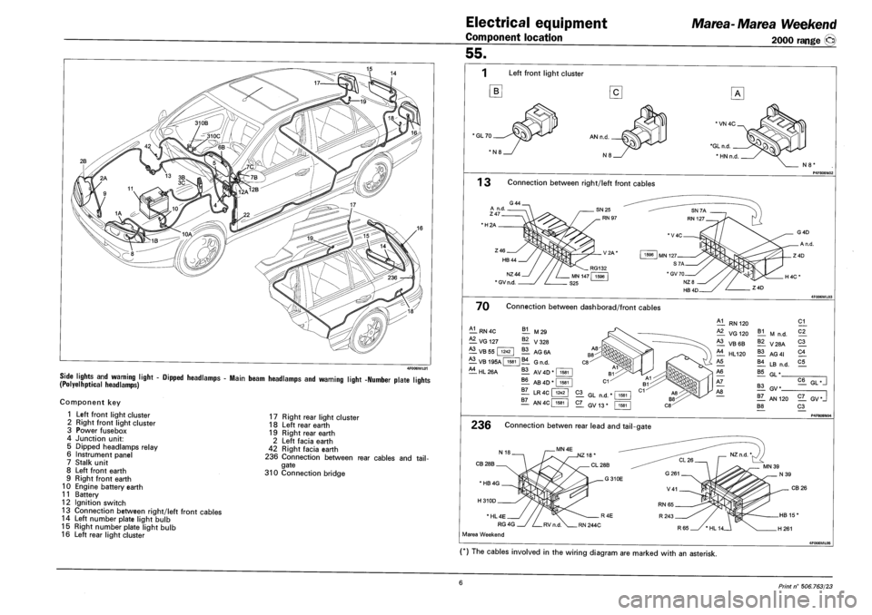
SIDE LIGHTS AND WARNING LIGHT - DIPPED HEADLAMPS - MAIN BEAM HEADLAMPS AND WARNING LIGHT -NUMBER PLATE LIQHTS (POLYELHPTICAL HEADLAMPS) r »
Component key
1 Left front light cluster
2 Right front light cluster
3 Power fusebox
4 Junction unit:
5 Dipped headlamps relay
6 Instrument panel
7 Stalk unit
8 Left front earth
9 Right front earth
10 Engine battery earth
11 Battery
12 Ignition switch
13 Connection between right/left front cables
14 Left number plate light bulb
15 Right number plate light bulb
16 Left rear light cluster
17 Right rear light cluster
18 Left rear earth
19 Right rear earth
2 Left facia earth
42 Right facia earth
236 Connection between rear cables and tail
gate
310 Connection bridge
Electrical equipment
Component location
Marea-Marea Weekend
2000 range (§)
55.
Left front light cluster
B
'GL70
N8'
1 3 Connection between right/left front cables
•H2A
NZ44
* GV n.d.
70 Connection between dashborad/front cables
A1
— RN 4C
— VG 127
B1 M29
^1 VB 55 | 1242
A3
— V328
11 AG6A
VB 195A | 1581 |B4 GN D
^1 HL 26A 11 AV 4D * I 1581
?! AB 4D"
11 LR 4C f
1581
1242
1Z_ AN4C| 1581
RN 120
VG 120
^1 VB6B
£1 HL120
B1 M n.d.
11 V28A
11 AG 41
11 LB n.d.
21
C2_
21
21
C5
B5 GL"
21 GL n.d.
2L GV13*
11 GV*
!T_ AN 120
B8
C6 GL •
2Z_ GV*J
21 P4F808NO4
236 Connection betwen rear lead and tail-gate
CB 28B
CB 26
* HL 4E
RG 4G
Marea Weekend
(*) The cables involved in the wiring diagram are marked with an asterisk.
6 Print n° 506.763/23
Page 194 of 330
Electrical equipment
Component location
Marea-Marea Weekend
2000 range ©
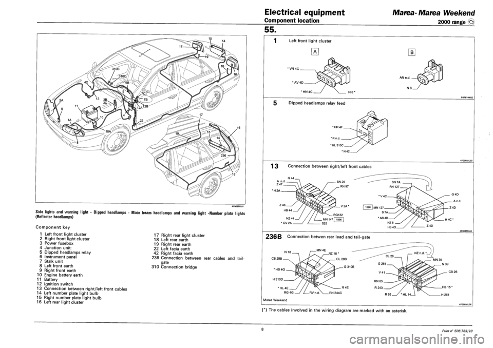
SIDE LIGHTS AND WARNING LIGHT - DIPPED HEADLAMPS - MAIN BEAM HEADLAMPS AND WARNING LIGHT -NUMBER PLATE LIGHTS
(REFLECTOR HEADLAMPS)
Component key
1 Left front light cluster
2 Right front light cluster
3 Power fusebox
4 Junction unit:
5 Dipped headlamps relay
6 Instrument panel
7 Stalk unit
8 Left front earth
9 Right front earth
10 Engine battery earth
11 Battery
12 Ignition switch
13 Connection between right/left front cables
14 Left number plate light bulb
15 Right number plate light bulb
16 Left rear light cluster
17 Right rear light cluster
18 Left rear earth
19 Right rear earth
22 Left facia earth
42 Right facia earth
236 Connection between rear cables and tail
gate
310 Connection bridge
55.
1 Left front light cluster
*VN 4C
' AV4D
B
AN n.d.
N8 *HN4C N8'
Dipped headlamps relay feed
' HR4F
1 3 Connection between right/left front cables
•H2A
236B Connection betwen rear lead and tail-gate
CB 28B
H4C*
CB 26
Marea Weekend
(*) The cables involved in the wiring diagram are marked with an asterisk.
8 Print n° 506.763/23
Page 196 of 330
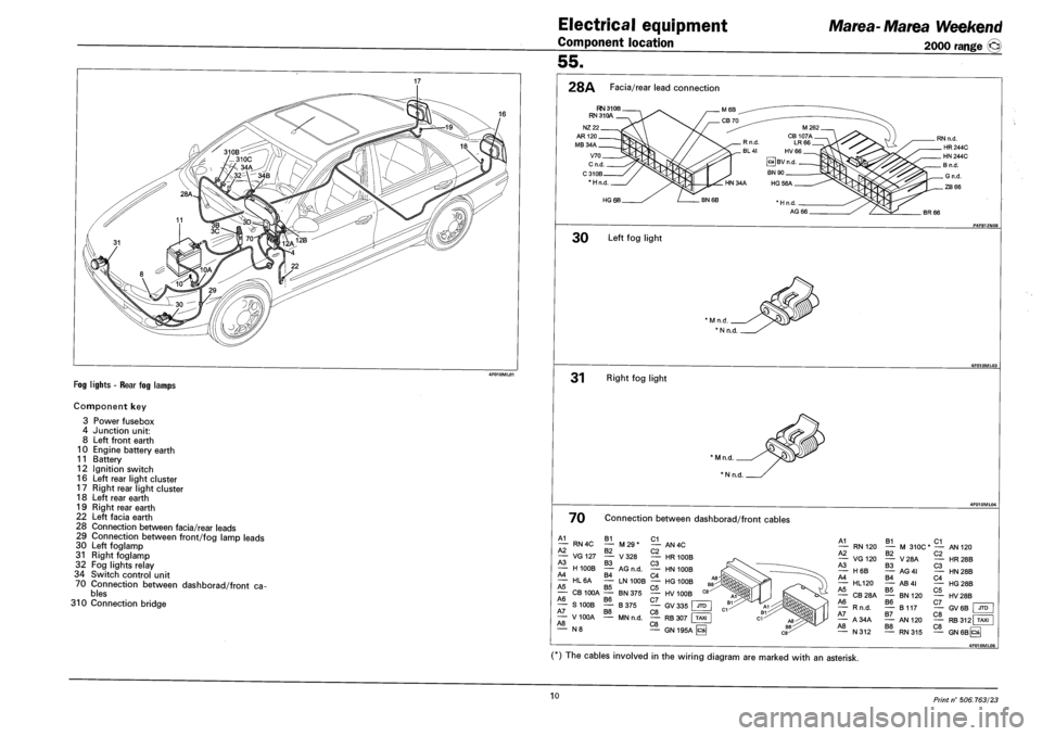
FOG LIGHTS - REAR FOG LAMPS
Component key
3 Power fusebox
4 Junction unit:
8 Left front earth
10 Engine battery earth
11 Battery
12 Ignition switch
16 Left rear light cluster
17 Right rear light cluster
18 Left rear earth
19 Right rear earth
22 Left facia earth
28 Connection between facia/rear leads
29 Connection between front/fog lamp leads
30 Left foglamp
31 Right foglamp
32 Fog lights relay
34 Switch control unit
70 Connection between dashborad/front cables
310 Connection bridge
Electrical equipment
Component location
Marea- Ma tea Weekend
2000 range ©
55.
28A Facia/rear lead connection
RN 31 OB RN 31 OA
* H n.d
HG 6B
BR 66
30 Left fog light
31 Right fog light
' M n.d.
* N n.d.
70 Connection between dashborad/front cables
A1 B1 C1 — RN4C — M29* — AN4C A2 B2 C2 — VG127 — V328 — HR 100B A3 B3 C3 — H100B — AG n.d. — HN 100B A4 B4 C4 — HL6A — LN 100B — HG 100B A5 B5 C5 - CB 100A — BN 375 — HV 100B A6 B6 C7 , — S100B — B375 — GV335 JTD A7 B8 C8 F= — V100A — MN n.d. — RB 307 TAXI A8 C8 " N 8 — GN 195A H
A1 — RN 120 A2 — VG120 A3 — H6B A4 — HL120 A5 — CB28A A6 — Rn.d. A7 — A34A A8 — N312
B1 C1 — M 310C* — AN B2 — V28A B3 — AG4I B4 — AB4I B5 — BN 120 B6 — B117 B7 — AN 120 B8 — RN315
C2 — HR C3 — HN C4 — HG C5 — HV C7 — GV C8 — RB C8 — GN
120
28B
28B
28B
28B
6B I JTD
312 TAXI
6Bps|
4F010ML0S
(*) The cables involved in the wiring diagram are marked with an asterisk.
10 Print n° 506.763/23
Page 198 of 330
Electrical system
Component location
Marea- Marea Weekend
2000 range ©
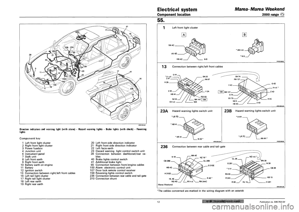
DIRECTION INDICATORS AND WARNING LIGHT (WITH ALARM)
LIGHTS
Component key
1 Left front light cluster
2 Right front light cluster
3 Power fusebox
4 Junction unit
6 Instrument panel
7 Stalk unit
8 Left front earth
9 Right front earth
10 Battery earth on engine
11 Battery
12 Ignition switch
13 Connection between right/left front cables
16 Left tail light cluster
17 Right tail light cluster
18 Left rear earth
19 Right rear earth
HAZARD WARNING LIGHTS - BRAKE LIGHTS (WITH CHECK) - REVERSING
20 Left front side direction indicator
21 Right front side direction indicator
22 Left facia earth
23 Hazard warning light control switch unit
28 Connection between dashborad/rear ca
bles
40 Brake lights control switch
41 Additional brake light
55 Connection between front/engine cables
100 Alarm electronic control unit
107 Door lock remote control receiver
159 Reversing lights control switch
236 Connection between rear cable and tail-gate
310 Connection shunt
55.
Left front light cluster
VN4C
AV4D
B
* AN n.d.
HN4C N8
1 3 Connection between right/left front cables
H2A
23A Hazard warning lights switch unit
'LB 7D
*AB4I
'AR4I
23B Hazard warning lights switch unit
*A4H .
' LR 7C AN 4H'
236 Connection between rear cable and tail-gate
CB28B
CB 26
HL 4E
RG4G
Marea Weekend
"The cables concerned are marked in the wiring diagram with an asterisk
12 XII 00 &jiii!-»cdes OMtfiuii.-. vtrsiun Publication no. 506.763/24
Page 200 of 330
Electrical system
Component location
Marea- Marea Weekend
2000 range ©
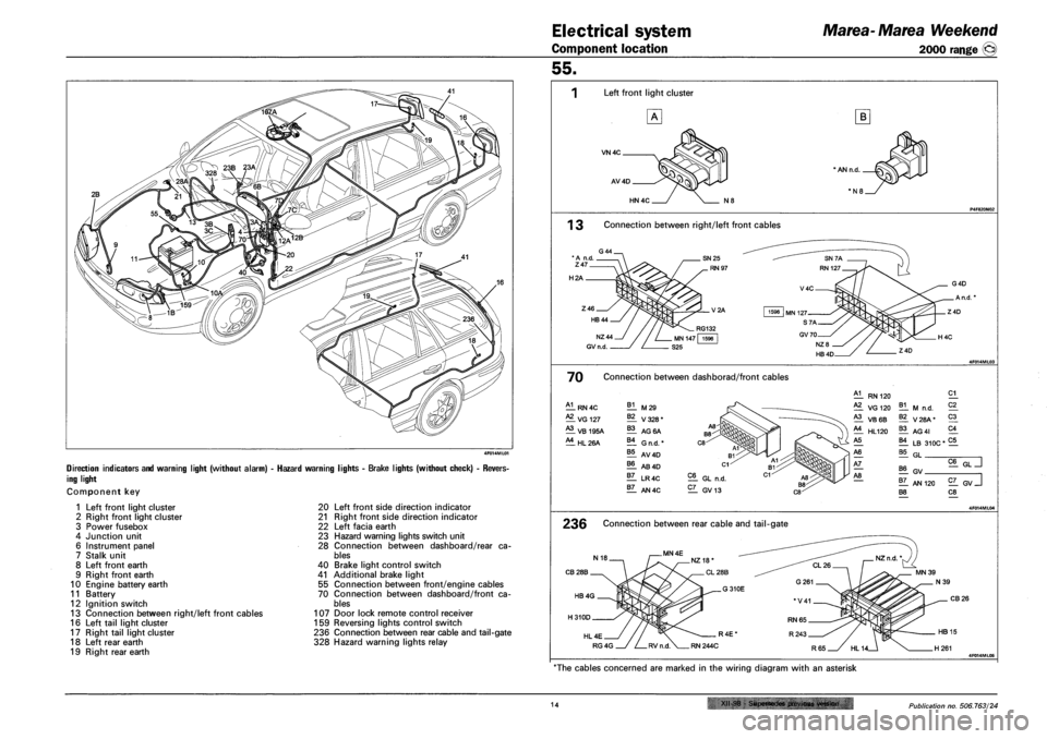
DIRECTION INDICATORS AND WARNING LIGHT (WITHOUT ALARM) - HAZARD WARNING
ING LIGHT
Component key
IGHTS - BRAKE LIGHTS (WITHOUT CHECK) - REVERS-
1 Left front light cluster
2 Right front light cluster
3 Power fusebox
4 Junction unit
6 Instrument panel
7 Stalk unit
8 Left front earth
9 Right front earth
10 Engine battery earth
11 Battery
12 Ignition switch
13 Connection between right/left front cables
16 Left tail light cluster
17 Right tail light cluster
18 Left rear earth
19 Right rear earth
20 Left front side direction indicator
21 Right front side direction indicator
22 Left facia earth
23 Hazard warning lights switch unit
28 Connection between dashboard/rear ca
bles
40 Brake light control switch
41 Additional brake light
55 Connection between front/engine cables
70 Connection between dashboard/front ca
bles
107 Door lock remote control receiver
159 Reversing lights control switch
236 Connection between rear cable and tail-gate
328 Hazard warning lights relay
55.
Left front light cluster
VN4C
AV4D
B
HN 4C
1 3 Connection between right/left front cables
H2A
70 Connection between dashborad/front cables
A1 RN4C B1 M29 A2 VG 127 B2 V328* A3 VB 195A B3 AG 6A A4 HL26A B4 G n.d. * B5 AV4D B6 AB4D B7 LR4C B7 AN4C
EL GL n.d.
EL GV13
5§^LT]
El GV
1L AN 120 EL GV J B8 C8
236 Connection between rear cable and tail-gate
CB28B
CB26
HL4E
RG4G 4F014ML05
"The cables concerned are marked in the wiring diagram with an asterisk
14 XII-98 - Supersedes previous version Publication no. 506.763/24
Page 202 of 330
4F016ML01
FIAT MAREA
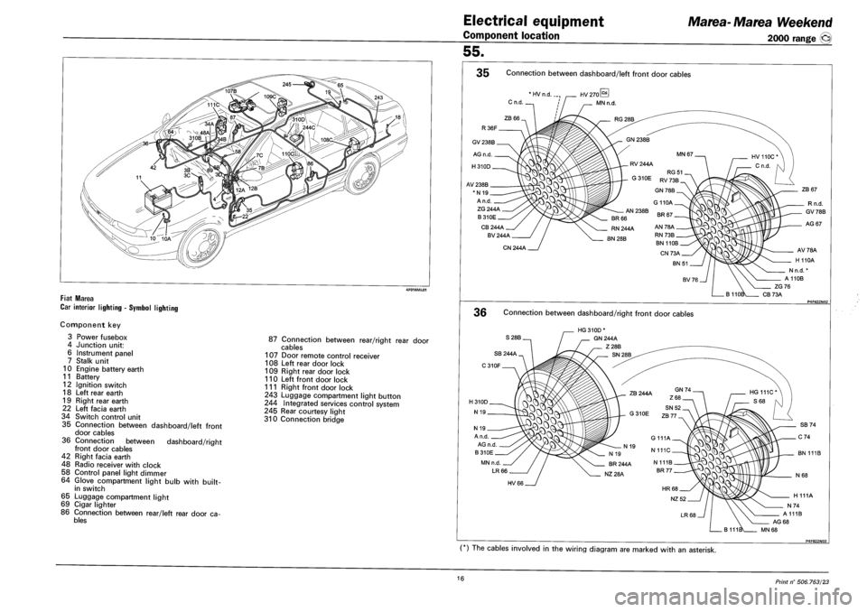
CAR INTERIOR LIGHTING - SYMBOL LIGHTING
Component key
3 Power fusebox
4 Junction unit:
6 Instrument panel
7 Stalk unit
10 Engine battery earth
11 Battery
12 Ignition switch
18 Left rear earth
19 Right rear earth
22 Left facia earth
34 Switch control unit
35 Connection between dashboard/left front
door cables
36 Connection between dashboard/right
front door cables
42 Right facia earth
48 Radio receiver with clock
58 Control panel light dimmer
64 Glove compartment light bulb with built-
in switch
65 Luggage compartment light
69 Cigar lighter
86 Connection between rear/left rear door cables
87 Connection between rear/right rear door
cables
107 Door remote control receiver
108 Left rear door lock
109 Right rear door lock
110 Left front door lock
111 Right front door lock
243 Luggage compartment light button
244 Integrated services control system
245 Rear courtesy light
310 Connection bridge
Electrical equipment
Component location
55.
Marea-Marea Weekend
2000 range (§)
35 Connection between dashboard/left front door cables
* HV n.d
ZG 244A
B310E
CB 244A
BV 244A
CN 244A
36 Connection between dashboard/right front door cables
ZB 67
Rn.d.
GV 78B
AG 67
AV78A
H 110A
N n.d.
A110B
ZG76
CB73A
S28B. HG 310D*
GN 244A
Z28B
16 Print n° 506.763/23