speaker FIAT MAREA 2001 1.G Workshop Manual
[x] Cancel search | Manufacturer: FIAT, Model Year: 2001, Model line: MAREA, Model: FIAT MAREA 2001 1.GPages: 330
Page 149 of 330
Marea-Marea Weekend # *»
2000 range ©
Electrical system
Radio System
55.
GENERAL DESCRIPTION
The car radio reception and playing system has been developed with the acoustic properties of the pas
senger compartment in mind to offer outstanding sound reproduction at all times.
The system is installed on the car directly during production, without subsequent interventions. All wires
are integral with the car wiring.
The system includes:
- radio
- front speakers (with separate tweeters)
- rear speakers
- radio supply leads
- radio and speaker connection leads
- radio controls on steering wheel
- coaxial aerial connection lead
- stylus aerial on roof
- connection lead for CD changer, located in boot.
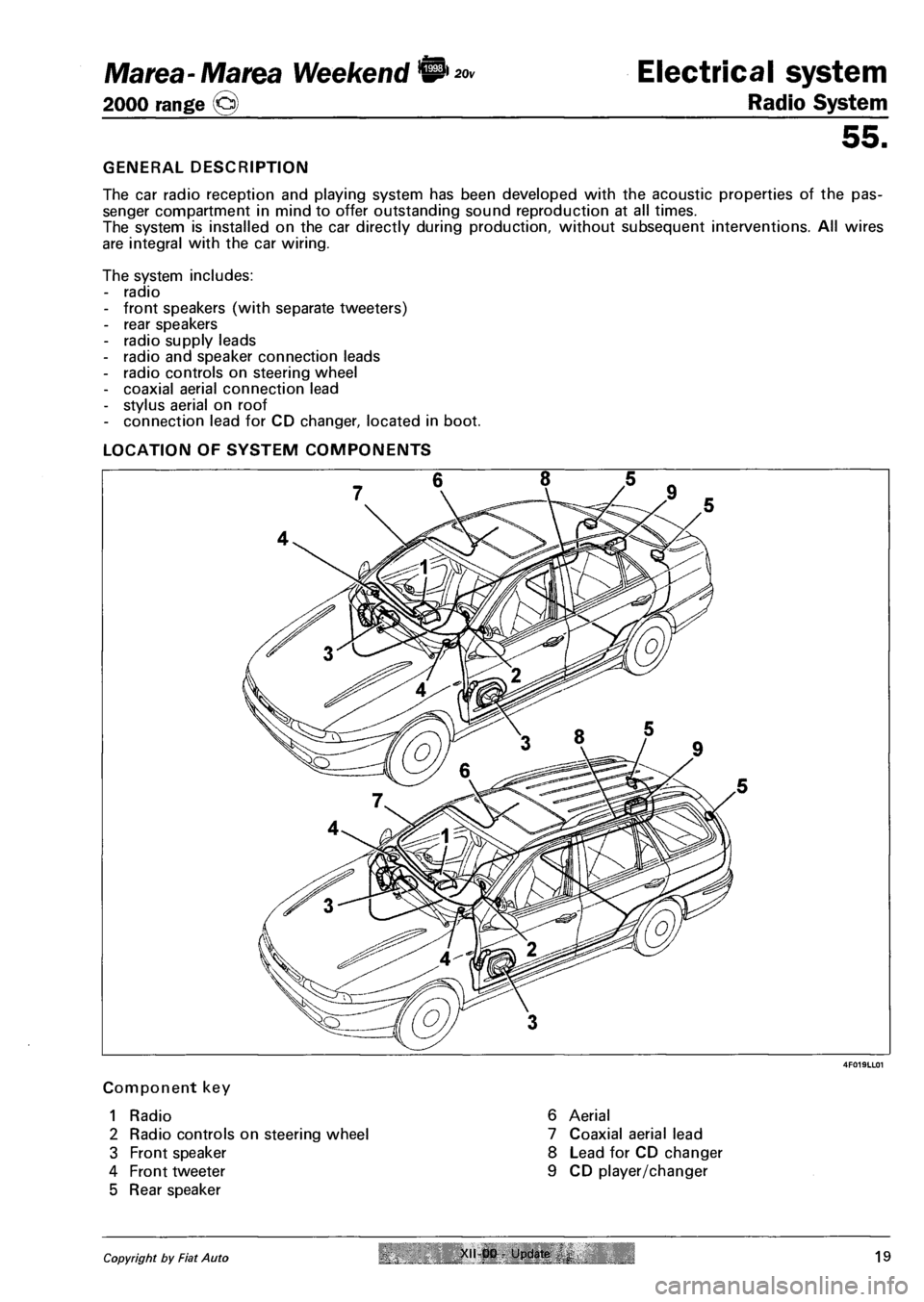
LOCATION OF SYSTEM COMPONENTS
Component key
1 Radio
2 Radio controls on steering wheel
3 Front speaker
4 Front tweeter
5 Rear speaker
6 Aerial
7 Coaxial aerial lead
8 Lead for CD changer
9 CD player/changer
Copyright by Fiat Auto XII-00 - Update 19
Page 150 of 330
Electrical system
Radio System
55.
CAR RADIO
The radio is customised to fit in with the instrument facia styling. It is fixed because it cannot be adapted
to any other car.
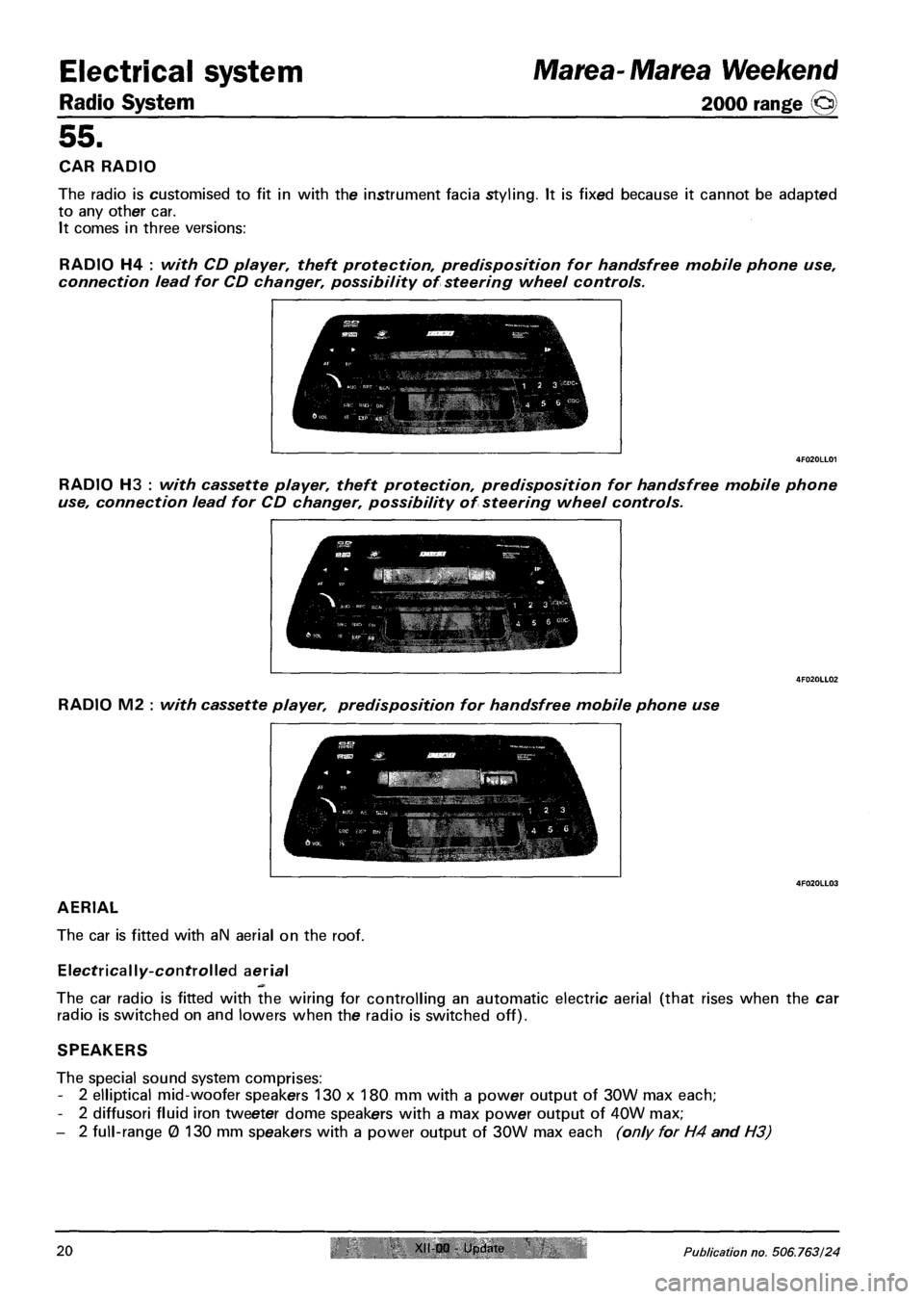
It comes in three versions:
RADIO H4 : with CD player, theft protection, predisposition for handsfree mobile phone use,
connection lead for CD changer, possibility of steering wheel controls.
RADIO H3 : with cassette player, theft protection, predisposition for handsfree mobile phone
use, connection lead for CD changer, possibility of steering wheel controls.
Marea-Marea Weekend
2000 range ©
RADIO M2 : with cassette player, predisposition for handsfree mobile phone use
AERIAL
The car is fitted with aN aerial on the roof.
Electrically-controlled aerial
The car radio is fitted with the wiring for controlling an automatic electric aerial (that rises when the car
radio is switched on and lowers when the radio is switched off).
SPEAKERS
The special sound system comprises:
- 2 elliptical mid-woofer speakers 130 x 180 mm with a power output of 30W max each;
- 2 diffusori fluid iron tweeter dome speakers with a max power output of 40W max;
- 2 full-range 0 130 mm speakers with a power output of 30W max each (only for H4 and H3)
20 XII-00 - Update Publication no. 506.763/24
Page 151 of 330
Marea- Marea Weekend Electrical system
2000 range @ Radio System
55.
TECHNICAL DATA
Radio power (H4 and H3 versions)
- 4 x 15W (with standard sound system made up of mid-woofer + tweeter and full range speakers).
Radio power (version M2)
- 2x15W (with standard sound system made up of mid-woofer + tweeter speakers).
- 4 x 5W (with optional 4-channel speaker system that can be installed by After Market).
WARNING The standard system is 2 x 15W, If a 2 x 15W system is fitted, an adaptor is fitted be
tween radio and wiring.
Fuse
The radio is fitted with a 10A fuse (D). (5A for the M2 version)
.Li.
3 6
2 5
B I M 5i I
T^l A 4| 6| |
I I I
2| 4| | |
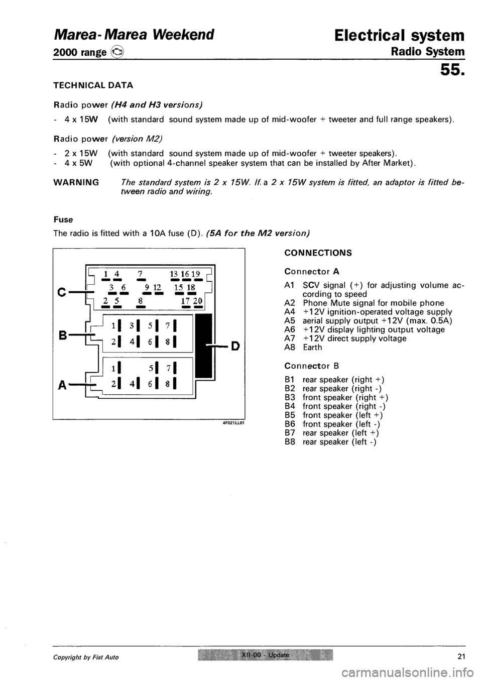
CONNECTIONS
Connector A
A1 SCV signal ( + ) for adjusting volume ac
cording to speed
A2 Phone Mute signal for mobile phone
A4 +12V ignition-operated voltage supply
A5 aerial supply output +12V (max. 0.5A)
A6 +12V display lighting output voltage
A7 +12V direct supply voltage
A8 Earth
Connector B
B1 rear speaker (right +)
B2 rear speaker (right -)
B3 front speaker (right +)
B4 front speaker (right -)
B5 front speaker (left +)
B6 front speaker (left -)
B7 rear speaker (left +)
B8 rear speaker (left -)
Copyright by Fiat Auto XII 00 Update 21
Page 152 of 330
Radio system
Electrical system Marea- Marea Weekend
2000 range @
55.
Supplementary connections
Connector C
Line output: possibility of connection for power amplifier (Booster)or active speaker
C1 Rear speaker (left +)
C2 Rear speaker (right +)
C3 Earth (-)
C4 Front speaker (left +)
C5 Front speaker (right +)
C6 Switch signal for power amplifier: on/off (max. 0.3A).
Phone input
Possibility of mobile phone handsfree connection
C7 NF phone
C12 NF phone earth
Remote control from steering wheel (H4 and H3 versions)
C8 Earth
C9 Remote control
Cd changer connection (H4 and H3 versions)
C13 CD bus control line
C15 CD bus earth
C16 +12V supply voltage for cd changer
C17 Switching voltage for cd changer
C18 NF CD earth
C19 left NF CD
C20 rifht NF CD
22 XII-00 - Update Publication no. 506.763/24
Page 164 of 330
Radio system
Electrical system Marea-Marea Weekend
2000 range @
55.
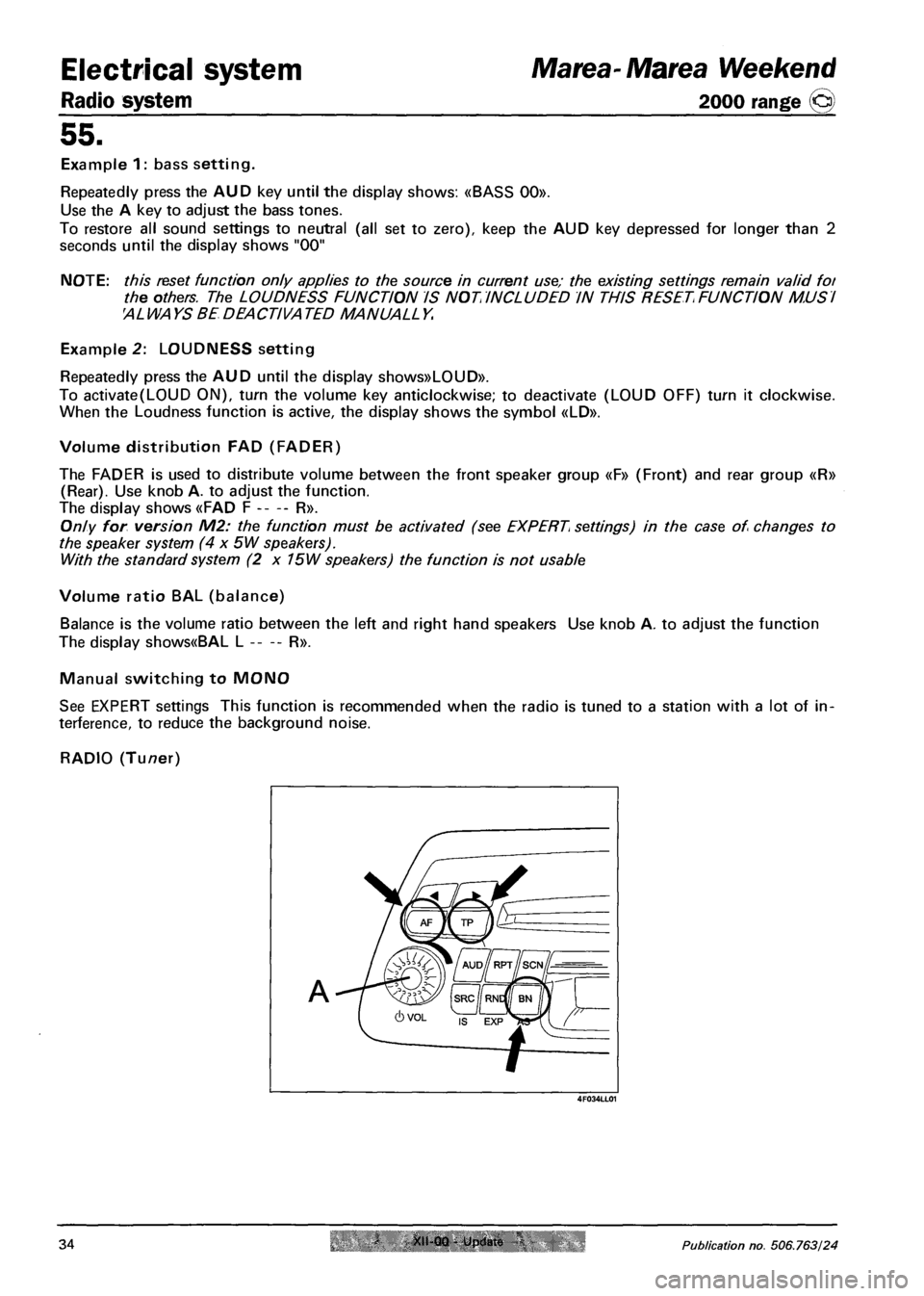
Example 1: bass setting.
Repeatedly press the AUD key until the display shows: «BASS 00».
Use the A key to adjust the bass tones.
To restore all sound settings to neutral (all set to zero), keep the AUD key depressed for longer than 2
seconds until the display shows "00"
NOTE: this reset function only applies to the source in current use; the existing settings remain valid foi
the others. The LOUDNESS FUNCTION IS NOT INCLUDED IN THIS RESET FUNCTION MUSI
AL WA YS BE DEACTIVA TED MANUALL Y.
Example 2: LOUDNESS setting
Repeatedly press the AUD until the display shows»LOUD».
To activate(L0UD ON), turn the volume key anticlockwise; to deactivate (LOUD OFF) turn it clockwise.
When the Loudness function is active, the display shows the symbol «LD».
Volume distribution FAD (FADER)
The FADER is used to distribute volume between the front speaker group «F» (Front) and rear group «R»
(Rear). Use knob A. to adjust the function.
The display shows «FAD F R».
Only for version M2: the function must be activated (see EXPERT settings) in the case of changes to
the speaker system (4 x 5W speakers).
With the standard system (2 x 75W speakers) the function is not usable
Volume ratio BAL (balance)
Balance is the volume ratio between the left and right hand speakers Use knob A. to adjust the function
The display shows«BAL L R».
Manual switching to MONO
See EXPERT settings This function is recommended when the radio is tuned to a station with a lot of in
terference, to reduce the background noise.
RADIO (Tuner)
A
4F034LL01
34 XII-00 - Update I Publication no. 506.763/24
Page 173 of 330
Marea-Marea Weekend Electrical system
2000 range (§j) Radio System
55.
10 - suppression of sound in case of incoming/outgoing phone call
- turn volume knob clockwise: «PHONE 0FF» no use of phone connection
- turn volume knob clockwise: «PH0NE 0N»: the radio sound is automatically deactivated in the case of
a phone call
The «PH0NE ON" function required the mobile phone mount base to be connected.
The «PH0NE IN» function allows a conversation via the car speakers in the case of a phone call.
The «PH0NE IN» function requires the mobile phone to be connected in handsfree mode
If the radio is off, a phone call (IN or OUT) is still possible. In this case the radio
- comes on automatically;
- allows listening under sound conditions identical to the last phone call (BASS, TREBLE, FADER,
BALANCE);
- goes off automatically at the end of the phone call
11 - setting mobile phone input sensitivity
Allows adaptation to the signal broadcast level for the type of handsfree system installed.
- turn volume knob anticlockwise: «PHONE 00» : low input sensitivity
- turn volume knob clockwise: «PHONE 03»: high input sensitivity
12 - security code activation
The code is not activated if «CODE» appears on the display.
If «SAFE» appears on the display, the code is activated.
NOTE: See next section for more detailed instructions.
13 - Controlling volume according to vehicle speed (SCV)
Standard value: «SCVOL 19»
Function off: «SCVOL - -«
Function at maximum efficiency: «SCVOL 34»
Setting:
1. Vehicle still, engine on: set required volume using the relevant knob.
2. Depress the EXP key for more than 2 seconds until «EXPERT» appears on the display.
3. Use keys A or B to select the «SCVOL» setting.
4. Set the required value using the volume knob:
- turn volume knob clockwise: VOL +
- turn volume knob anticlockwise: VOL -
14 - audible function confirmation (BEEP)
The BEEP function is active in the system
This function gives an audible confirmation (BEEP) of the functions. Function activation requires continu
ous pressing of the key for a time greater than or equal to 2 seconds.
15 - select MONO/STEREO radio reproduction
turn volume knob clockwise: «MONO ON».
turn volume knob anticlockwise: «MONO OFF».
16 - activate/deactivate LOC
The automatic search in the FM range may be used at two sensitivity levels When in search of stations,
the set may be tuned with high field intensity (local stations) or low field intensity (distant reception).
- turn volume knob clockwise: «LOC ON».
- turn volume knob anticlockwise: «LOC OFF».
Copyright by Fiat Auto XII-00 Updale 43
Page 206 of 330
Electrical equipment
Component location
Marea-Marea Weekend
2000 range ©
55.
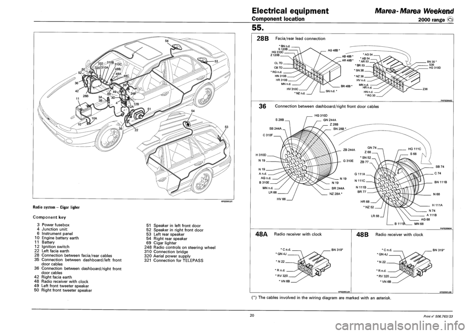
RADIO SYSTEM - CIGAR LIGHER
Component key
3 Power fusebox
4 Junction unit:
6 Instrument panel
10 Engine battery earth
11 Battery
12 Ignition switch
22 Left facia earth
28 Connection between facia/rear cables
35 Connection between dashboard/left front
door cables
36 Connection between dashboard/right front
door cables
42 Right facia earth
48 Radio receiver with clock
49 Left front tweeter speaker
50 Right front tweeter speaker
51 Speaker in left front door
52 Speaker in right front door
53 Left rear speaker
54 Right rear speaker
69 Cigar lighter
248 Radio controls on steering wheel
310 Connection bridge
320 Aerial power supply
321 Connection for TELEPASS
28B Facia/rear lead connection
* BN n.d. S 120B HG310C Z120B
AG 48B *
HV310C
* NZ n.d
AB48B* AB
AR48B* .AR
*BR53
*SN 36
BR 48B *
SN n.d.'
36 Connection between dashboard/right front door cables
S28B.
HG 310D
GN 244A
Z28B
N 19
A n.d
AG n.d
B310E
MN n.d.
LR 66
BN 111B
HV66
H 111A
A111B
AG 68
MN68
48A Radio receiver with clock
*N22
BN 319*
* R n.d
* RV 320
*VN 6B
48 B Radio receiver with clock
BN 319*
(*) The cables involved in the wiring diagram are marked with an asterisk.
20 Print n° 506.763/23
Page 282 of 330
Electrical equipment
Connector blocks
Marea-Marea Weekend
2000 range ©)
55.
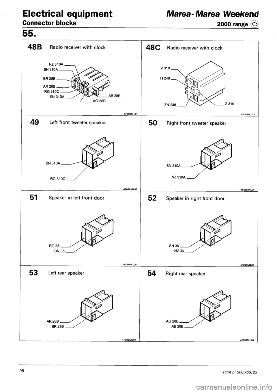
48 B Radio receiver with clock
NZ 310A
BN310A
BR 28B
AR 28B
RG310C
SN 31 OA AB28B
AG28B
49 Left front tweeter speaker
BN 31 OA
RG 31 OC
51 Speaker in left front door
RG35
BN 35
48C Radio receiver with clock
ZN248 Z319
50 Right front tweeter speaker
SN 310A
NZ310A
52 Speaker in right front door
SN36
NZ 36
53 Left rear speaker 54 Right rear speaker
AR 28B
BR 28B
AG28B
AB28B
96 Print n° 506.763/23
Page 328 of 330
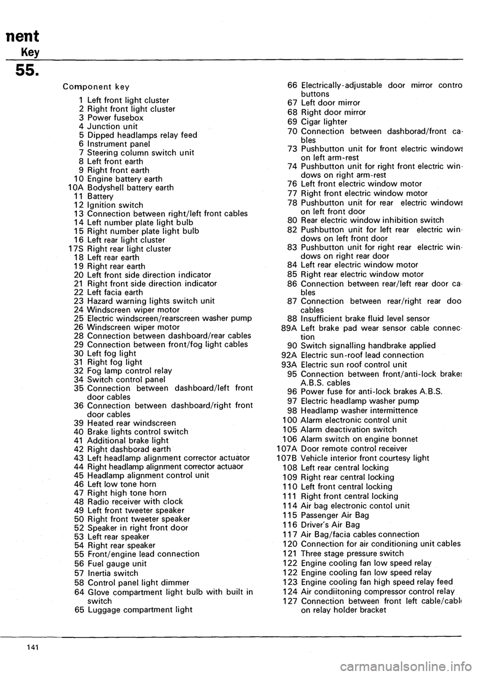
nent
Key
55.
Component key
1 Left front light cluster
2 Right front light cluster
3 Power fusebox
4 Junction unit
5 Dipped headlamps relay feed
6 Instrument panel
7 Steering column switch unit
8 Left front earth
9 Right front earth
10 Engine battery earth
10A Bodyshell battery earth
11 Battery
12 Ignition switch
13 Connection between right/left front cables
14 Left number plate light bulb
15 Right number plate light bulb
16 Left rear light cluster
17S Right rear light cluster
18 Left rear earth
19 Right rear earth
20 Left front side direction indicator
21 Right front side direction indicator
22 Left facia earth
23 Hazard warning lights switch unit
24 Windscreen wiper motor
25 Electric windscreen/rearscreen washer pump
26 Windscreen wiper motor
28 Connection between dashboard/rear cables
29 Connection between front/fog light cables
30 Left fog light
31 Right fog light
32 Fog lamp control relay
34 Switch control panel
35 Connection between dashboard/left front
door cables
36 Connection between dashboard/right front
door cables
39 Heated rear windscreen
40 Brake lights control switch
41 Additional brake light
42 Right dashborad earth
43 Left headlamp alignment corrector actuator
44 Right headlamp alignment corrector actuaor
45 Headlamp alignment control unit
46 Left low tone horn
47 Right high tone horn
48 Radio receiver with clock
49 Left front tweeter speaker
50 Right front tweeter speaker
52 Speaker in right front door
53 Left rear speaker
54 Right rear speaker
55 Front/engine lead connection
56 Fuel gauge unit
57 Inertia switch
58 Control panel light dimmer
64 Glove compartment light bulb with built in
switch
65 Luggage compartment light
66 Electrically-adjustable door mirror contro
buttons
67 Left door mirror
68 Right door mirror
69 Cigar lighter
70 Connection between dashborad/front ca
bles
73 Pushbutton unit for front electric windows
on left arm-rest
74 Pushbutton unit for right front electric win
dows on right arm-rest
76 Left front electric window motor
77 Right front electric window motor
78 Pushbutton unit for rear electric windows
on left front door
80 Rear electric window inhibition switch
82 Pushbutton unit for left rear electric win
dows on left front door
83 Pushbutton unit for right rear electric win
dows on right rear door
84 Left rear electric window motor
85 Right rear electric window motor
86 Connection between rear/left rear door ca
bles
87 Connection between rear/right rear doo
cables
88 Insufficient brake fluid level sensor
89A Left brake pad wear sensor cable connec
tion
90 Switch signalling handbrake applied
92A Electric sun-roof lead connection
93A Electric sun roof control unit
95 Connection between front/anti-lock brake;
A.B.S. cables
96 Power fuse for anti-lock brakes A.B.S.
97 Electric headlamp washer pump
98 Headlamp washer intermittence
100 Alarm electronic control unit
105 Alarm deactivation switch
106 Alarm switch on engine bonnet
107A Door remote control receiver
107B Vehicle interior front courtesy light
108 Left rear central locking
109 Right rear central locking
110 Left front central locking
111 Right front central locking
114 Air bag electronic contol unit
115 Passenger Air Bag
116 Driver's Air Bag
117 Air Bag/facia cables connection
120 Connection for air conditioning unit cables
121 Three stage pressure switch
122 Engine cooling fan low speed relay
122 Engine cooling fan low speed relay
123 Engine cooling fan high speed relay feed
124 Air condiitoning compressor control relay
127 Connection between front left cable/cabli
on relay holder bracket
141