change wheel FIAT PANDA 2015 319 / 3.G Owners Manual
[x] Cancel search | Manufacturer: FIAT, Model Year: 2015, Model line: PANDA, Model: FIAT PANDA 2015 319 / 3.GPages: 196, PDF Size: 19.49 MB
Page 2 of 196
We really know your car because we invented, designed and built it: we really know every single detail.
At Fiat Service authorised workshopsyou can find technicians directly trained by us,
offering quality and professionalism for all service operations.
Fiat workshops are always close to you for the regular servicing operations, season checks
and practical recommendations by our experts.
With Fiat Genuine Parts you keep the reliability, comfort and performance features
of your new car unchanged in time: that's why you bought it for.
Always ask for Genuine Parts for the components used on our cars; we recommend them because
they come from our steady commitment in research and development of highly innovative technologies.
For all these reasons: rely on Genuine Parts, because they are the only ones designed
by Fiat for your car.
SAFETY:
BRAKING SYSTEMENVIRONMENT: PARTICULATE FILTERS,
CLIMATE CONTROL MAINTENANCECOMFORT: SUSPENSION
AND WINDSCREEN WIPERS PERFORMANCE: SPARK PLUGS,
INJECTORS AND BATTERIESLINEACCESSORI
ROOF RACK BARS, WHEEL RIMS
WHY CHOOSING
GENUINE PARTS
COP PANDA UM GB SISTEMA 10/04/14 15:27 Pagina 2
Page 19 of 196
On automatic sensor controlled
deactivation, the dipped headlights are
deactivated first, followed by the side
lights a few seconds later.
If the sensor is activated but is
malfunctioning, the side lights and
dipped headlights are switched
on irrespective of the external lighting
conditions: the sensor failure is
indicated on the display. It is also
possible to deactivate the sensor and
switch on the desired lights, if
necessary.
IMPORTANT The sensor cannot detect
the presence of fog. These lights must
therefore be switched on manually in
these circumstances.
SIDE LIGHTS/DAYTIME
RUNNING LIGHTS (DRL)
"Daytime Running Lights"
(for versions/markets, where provided)
16) 17)
With the ignition key turned to MAR
and ring nut A fig. 18 turned to position
Othe daytime running lights are
automatically activated; the other lights
and interior lighting remain off.SIDE LIGHTS AND
DIPPED BEAM
HEADLIGHTS
With the ignition key turned to MAR,
turn ring nut A fig. 18 to
. If dipped
beam headlights are activated, the
daytime running lights switch off and
the side lights and dipped headlights
switch on. The
warning light
switches on in the instrument panel.
When the ignition key is turned to
STOP or removed and the ring nut A is
turned fromOto
, all the side
lights and the number plate lights come
on. The
warning light will come
on in the instrument panel.
PARKING LIGHTS
These lights can only be turned on with
ignition key in STOP position or
removed, by moving the ring nut A fig.
18 first to positionOand then to
position
.
The
warning light switches on in
the instrument panel.
MAIN BEAM HEADLIGHTS
To activate the main beam headlights,
with ring nut A fig. 18 at
, pull the
stalk towards the steering wheel
beyond the end of travel position. The
warning light switches on in the
instrument panel.When the stalk is pulled towards the
steering wheel again, beyond the end
of travel position, the main beam
headlights are deactivated, the dipped
beam headlights are reactivated and
the
warning light switches off.
FLASHING
To do this, pull the stalk towards the
steering wheel (unstable position)
regardless of the position of ring nut A
fig. 18. The
warning light switches
on in the instrument panel.
DIRECTION INDICATORS
Bring the stalk to the (stable) position:
upwards:activates the right direction
indicator;
downwards:activates the left direction
indicator.
Warning light
orwill blink on the
instrument panel. The direction
indicators switch off automatically when
the steering wheel is straightened.
"Lane Change" function
If you wish to signal a lane change,
place the left stalk in the unstable
position for less than half a second. The
direction indicator on the side selected
will flash five times and then switch
off automatically.
17
Page 70 of 196
Driving in special conditions
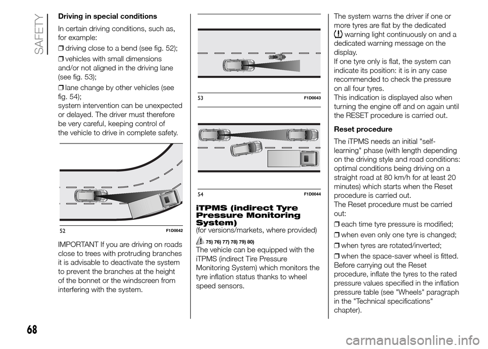
In certain driving conditions, such as,
for example:
❒driving close to a bend (see fig. 52);
❒vehicles with small dimensions
and/or not aligned in the driving lane
(see fig. 53);
❒lane change by other vehicles (see
fig. 54);
system intervention can be unexpected
or delayed. The driver must therefore
be very careful, keeping control of
the vehicle to drive in complete safety.
IMPORTANT If you are driving on roads
close to trees with protruding branches
it is advisable to deactivate the system
to prevent the branches at the height
of the bonnet or the windscreen from
interfering with the system.iTPMS (indirect Tyre
Pressure Monitoring
System)
(for versions/markets, where provided)
75) 76) 77) 78) 79) 80)
The vehicle can be equipped with the
iTPMS (indirect Tire Pressure
Monitoring System) which monitors the
tyre inflation status thanks to wheel
speed sensors.The system warns the driver if one or
more tyres are flat by the dedicated
warning light continuously on and a
dedicated warning message on the
display.
If one tyre only is flat, the system can
indicate its position: it is in any case
recommended to check the pressure
on all four tyres.
This indication is displayed also when
turning the engine off and on again until
the RESET procedure is carried out.
Reset procedure
The iTPMS needs an initial "self-
learning" phase (with length depending
on the driving style and road conditions:
optimal conditions being driving on a
straight road at 80 km/h for at least 20
minutes) which starts when the Reset
procedure is carried out.
The Reset procedure must be carried
out:
❒each time tyre pressure is modified;
❒when even only one tyre is changed;
❒when tyres are rotated/inverted;
❒when the space-saver wheel is fitted.
Before carrying out the Reset
procedure, inflate the tyres to the rated
pressure values specified in the inflation
pressure table (see "Wheels" paragraph
in the "Technical specifications"
chapter).
52F1D0042
53F1D0043
54F1D0044
68
SAFETY
Page 93 of 196
WARNING
122)Never leave children unattended in
the vehicle. Always remove the key from
the ignition device when leaving the vehicle
and take it with you.
123)The vehicle should be braked after a
few clicks of the lever, if it is not, contact
a Fiat Dealership to have it adjusted.
124)In the case of parking manoeuvres on
roads on a gradient, the front wheels
must be steered towards the pavement
(when parking downhill), or in the opposite
direction if the vehicle is parked uphill. If
the vehicle is parked on a steep slope, it is
also advisable to block the wheels with a
wedge or stone.
MANUAL GEARBOX
125)42)
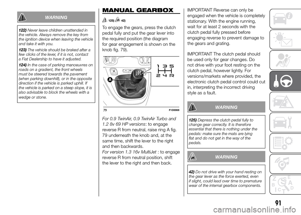
To engage the gears, press the clutch
pedal fully and put the gear lever into
the required position (the diagram
for gear engagement is shown on the
knob fig. 79).
For 0.9 TwinAir, 0.9 TwinAir Turbo and
1.2 8v 69 HP versions: to engage
reverse R from neutral, raise ring A fig.
79 underneath the knob and, at the
same time, shift the lever to the right
and then backwards.
For version 1.3 16v MultiJet: to engage
reverse R from neutral position, shift
the lever to the right and then back.IMPORTANT Reverse can only be
engaged when the vehicle is completely
stationary. With the engine running,
wait for at least 2 seconds with the
clutch pedal fully pressed before
engaging reverse to prevent damage to
the gears and grating.
IMPORTANT The clutch pedal should
be used only for gear changes. Do
not drive with your foot resting on the
clutch pedal, however lightly. For
versions/markets where provided, the
electronic clutch pedal control could cut
in, interpreting the incorrect driving
style as a fault.
WARNING
125)Depress the clutch pedal fully to
change gear correctly. It is therefore
essential that there is nothing under the
pedals: make sure the mats are lying
flat and do not get in the way of the
pedals.
WARNING
42)Do not drive with your hand resting on
the gear lever as the force exerted, even
if slight, could lead over time to premature
wear of the internal gearbox components.
79F1D0069
91
Page 107 of 196
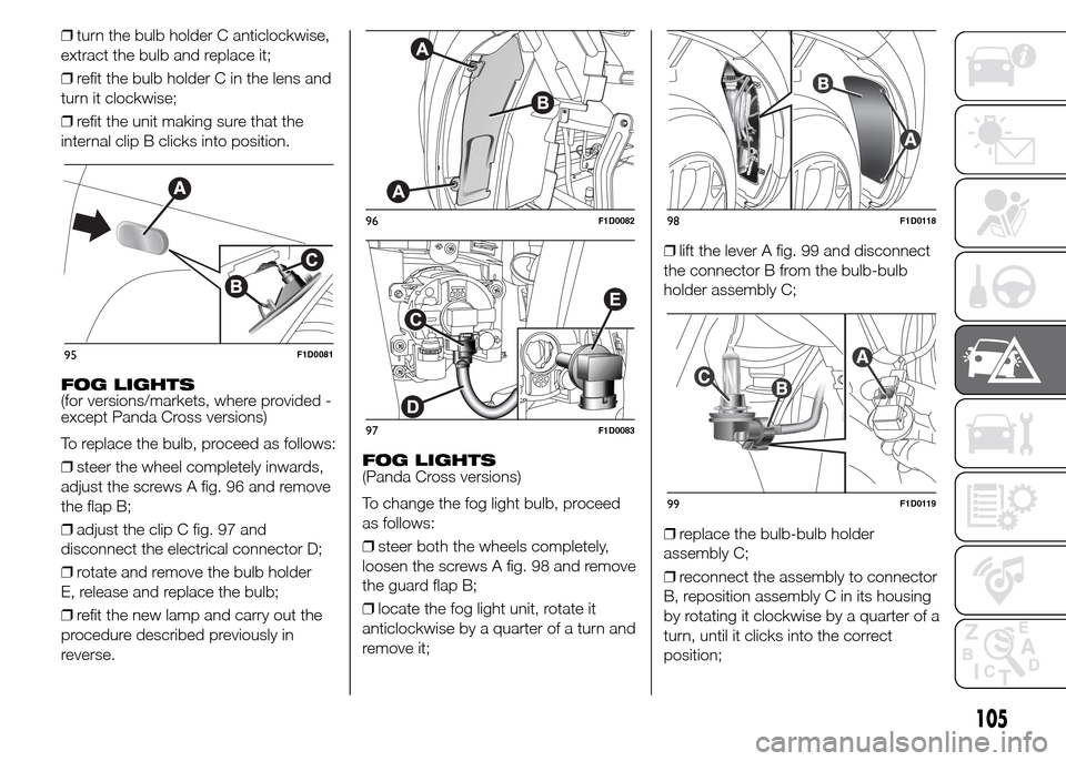
❒turn the bulb holder C anticlockwise,
extract the bulb and replace it;
❒refit the bulb holder C in the lens and
turn it clockwise;
❒refit the unit making sure that the
internal clip B clicks into position.
FOG LIGHTS
(for versions/markets, where provided -
except Panda Cross versions)
To replace the bulb, proceed as follows:
❒steer the wheel completely inwards,
adjust the screws A fig. 96 and remove
the flap B;
❒adjust the clip C fig. 97 and
disconnect the electrical connector D;
❒rotate and remove the bulb holder
E, release and replace the bulb;
❒refit the new lamp and carry out the
procedure described previously in
reverse.FOG LIGHTS
(Panda Cross versions)
To change the fog light bulb, proceed
as follows:
❒steer both the wheels completely,
loosen the screws A fig. 98 and remove
the guard flap B;
❒locate the fog light unit, rotate it
anticlockwise by a quarter of a turn and
remove it;❒lift the lever A fig. 99 and disconnect
the connector B from the bulb-bulb
holder assembly C;
❒replace the bulb-bulb holder
assembly C;
❒reconnect the assembly to connector
B, reposition assembly C in its housing
by rotating it clockwise by a quarter of a
turn, until it clicks into the correct
position;
95F1D0081
96F1D0082
97F1D0083
98F1D0118
99F1D0119
105
Page 108 of 196
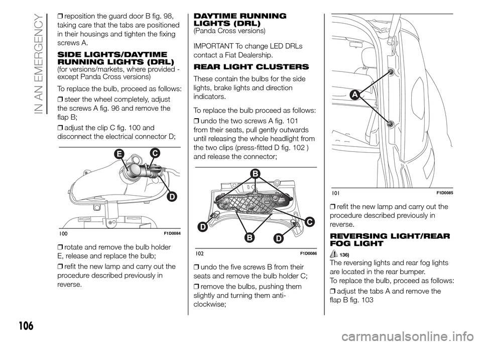
❒reposition the guard door B fig. 98,
taking care that the tabs are positioned
in their housings and tighten the fixing
screws A.
SIDE LIGHTS/DAYTIME
RUNNING LIGHTS (DRL)
(for versions/markets, where provided -
except Panda Cross versions)
To replace the bulb, proceed as follows:
❒steer the wheel completely, adjust
the screws A fig. 96 and remove the
flap B;
❒adjust the clip C fig. 100 and
disconnect the electrical connector D;
❒rotate and remove the bulb holder
E, release and replace the bulb;
❒refit the new lamp and carry out the
procedure described previously in
reverse.DAYTIME RUNNING
LIGHTS (DRL)
(Panda Cross versions)
IMPORTANT To change LED DRLs
contact a Fiat Dealership.
REAR LIGHT CLUSTERS
These contain the bulbs for the side
lights, brake lights and direction
indicators.
To replace the bulb proceed as follows:
❒undo the two screws A fig. 101
from their seats, pull gently outwards
until releasing the whole headlight from
the two clips (press-fitted D fig. 102 )
and release the connector;
❒undo the five screws B from their
seats and remove the bulb holder C;
❒remove the bulbs, pushing them
slightly and turning them anti-
clockwise;❒refit the new lamp and carry out the
procedure described previously in
reverse.
REVERSING LIGHT/REAR
FOG LIGHT
136)
The reversing lights and rear fog lights
are located in the rear bumper.
To replace the bulb, proceed as follows:
❒adjust the tabs A and remove the
flap B fig. 103
100F1D0084
102F1D0086
101F1D0085
106
IN AN EMERGENCY
Page 113 of 196
WARNING
137)If the replaced fuse blows again,
contact a Fiat Dealership.
138)Never replace a blown fuse with metal
wires or other material.
139)Never replace a fuse with another with
a higher amp rating; DANGER OF FIRE.
140)If a general fuse (MEGA-FUSE,
MIDI-FUSE, MAXI-FUSE) cuts in, do not
attempt any repair and contact a Fiat
Dealership.
141)Before replacing a fuse, make sure
that the ignition key has been removed and
that all the other devices are switched off
and/or deactivated.
142)If a general protection fuse for safety
systems (airbag system, braking system),
power unit systems (engine system,
transmission system) or steering system
blows, contact a Fiat Dealership.
WARNING
50)If you need to wash the engine
compartment, take care not to directly hit
the fuse box and the window wiper motors
with the water jet.
CHANGING A WHEEL
143) 144) 145) 146) 147)
JACK
Important notes:
❒the jack weight is 1.76 kg;
❒the jack requires no adjustment;
❒the jack cannot be repaired and in
the event of a fault it must be replaced
by another original one;
❒no tool other than its cranking device
may be fitted on the jack.
CHANGING PROCEDURE
Proceed as follows:
❒stop the vehicle in a position that is
not dangerous for oncoming traffic
where you can change the wheel safely.
The ground should be flat if possible,
and sufficiently firm;
❒switch off the engine, pull up the
handbrake and engage the 1
stgear or
reverse. Wear the reflective safety
jacket (compulsory by law) before
getting out of the vehicle;
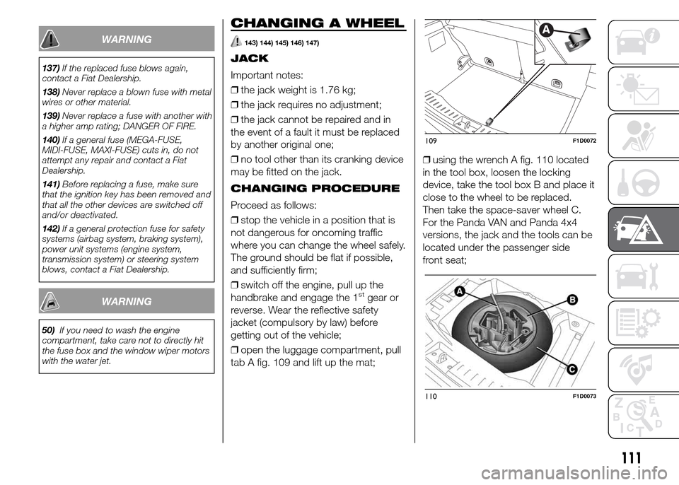
❒open the luggage compartment, pull
tab A fig. 109 and lift up the mat;❒using the wrench A fig. 110 located
in the tool box, loosen the locking
device, take the tool box B and place it
close to the wheel to be replaced.
Then take the space-saver wheel C.
For the Panda VAN and Panda 4x4
versions, the jack and the tools can be
located under the passenger side
front seat;
109F1D0072
110F1D0073
111
Page 114 of 196
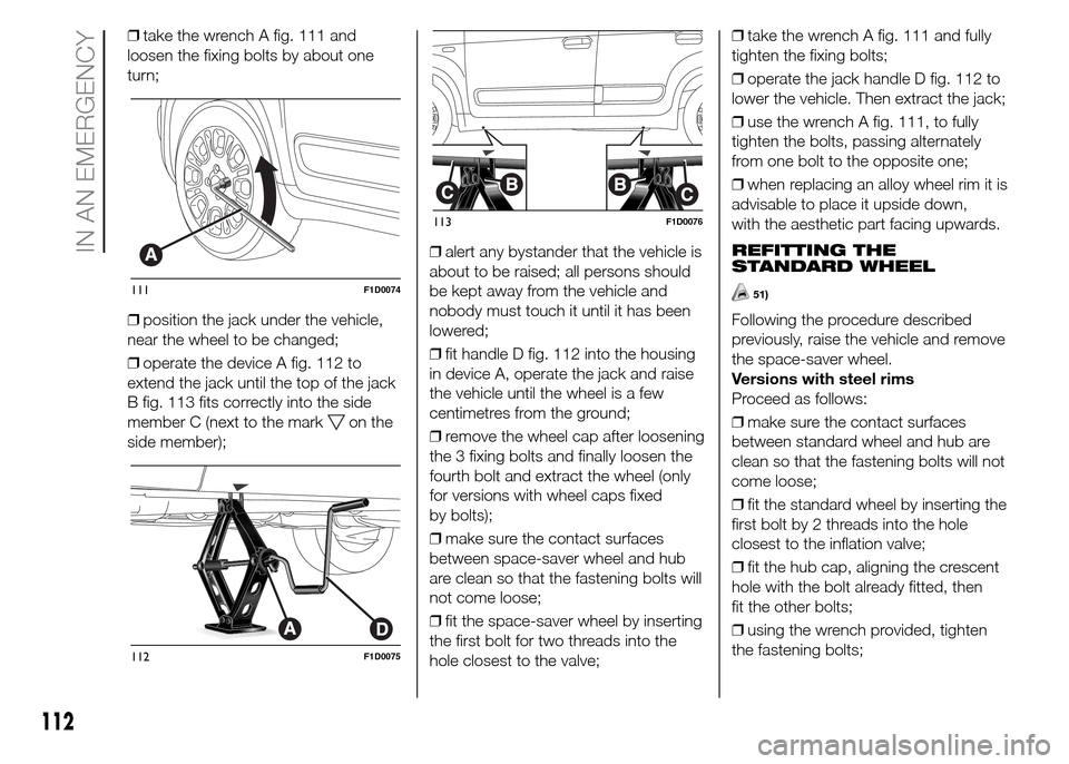
❒take the wrench A fig. 111 and
loosen the fixing bolts by about one
turn;
❒position the jack under the vehicle,
near the wheel to be changed;
❒operate the device A fig. 112 to
extend the jack until the top of the jack
B fig. 113 fits correctly into the side
member C (next to the mark
on the
side member);❒alert any bystander that the vehicle is
about to be raised; all persons should
be kept away from the vehicle and
nobody must touch it until it has been
lowered;
❒fit handle D fig. 112 into the housing
in device A, operate the jack and raise
the vehicle until the wheel is a few
centimetres from the ground;
❒remove the wheel cap after loosening
the 3 fixing bolts and finally loosen the
fourth bolt and extract the wheel (only
for versions with wheel caps fixed
by bolts);
❒make sure the contact surfaces
between space-saver wheel and hub
are clean so that the fastening bolts will
not come loose;
❒fit the space-saver wheel by inserting
the first bolt for two threads into the
hole closest to the valve;❒take the wrench A fig. 111 and fully
tighten the fixing bolts;
❒operate the jack handle D fig. 112 to
lower the vehicle. Then extract the jack;
❒use the wrench A fig. 111, to fully
tighten the bolts, passing alternately
from one bolt to the opposite one;
❒when replacing an alloy wheel rim it is
advisable to place it upside down,
with the aesthetic part facing upwards.
REFITTING THE
STANDARD WHEEL
51)
Following the procedure described
previously, raise the vehicle and remove
the space-saver wheel.
Versions with steel rims
Proceed as follows:
❒make sure the contact surfaces
between standard wheel and hub are
clean so that the fastening bolts will not
come loose;
❒fit the standard wheel by inserting the
first bolt by 2 threads into the hole
closest to the inflation valve;
❒fit the hub cap, aligning the crescent
hole with the bolt already fitted, then
fit the other bolts;
❒using the wrench provided, tighten
the fastening bolts;
111F1D0074
112F1D0075
113F1D0076
112
IN AN EMERGENCY
Page 115 of 196
❒lower the vehicle and remove the
jack;
❒use the wrench provided to fully
tighten the bolts, passing alternately
from one bolt to the opposite one.
Versions with alloy wheels
Proceed as follows:
❒insert the wheel on the hub and using
the wrench provided tighten the bolts;
❒lower the vehicle and remove the
jack;
❒use the wrench provided to fully
tighten the bolts, passing alternately
from one bolt to the opposite one.
❒reinsert the press-fitted hub cap,
making sure that the reference hole on
the wheel is aligned with the reference
pin on the cap.
IMPORTANT If it is not fitted properly,
the hub cap may detach itself when the
vehicle is running.
At the end of operation
❒stow the space-saver wheel in the
compartment provided in the luggage
compartment;
❒insert the jack and the other tools in
the container;
❒arrange the container and tools on
the space-saver wheel;
❒correctly reposition the boot mat.
WARNING
143)The space-saver wheel (for
versions/markets, where provided) is
specific to your vehicle, do not use it on
other models, or use the space-saver
wheel of other models on your vehicle. The
space-saver wheel must only be used in
the event of an emergency. It must only be
used for the distance necessary to reach
a service point and the vehicle speed must
not exceed 80 km/h. The space-saver
wheel has an orange label that
summarises the main cautions for use and
limitations. Never remove or cover the
label. The following information is provided
in four languages on the label: "Important!
For temporary use only! 80 km/h max!
Replace with a standard wheel as soon as
possible. Never cover this indication".
Never apply any hub cap to the
space-saver wheel.
144)Use your hazard lights, warning
triangle, etc to show that your vehicle is
stationary. Passengers should get out
of the vehicle, particularly if it is heavily
loaded, and wait for the wheel to be
changed away from the traffic. On hills or
uneven roads, use chocks or appropriate
objects to block the wheels of the vehicle.145)The vehicle's driving characteristics
will be modified with the space-saver wheel
fitted. Avoid violent acceleration and
braking, abrupt steering and fast cornering.
The overall duration of the space-saver
wheel is about 3000 km, after which the
relevant tyre must be replaced with another
one of the same type. Never install a
traditional tyre on a rim designed to be
used as a space-saver wheel. Have the
wheel repaired and refitted as soon as
possible. Using two or more space-saver
wheels at the same time is forbidden.
Do not apply grease to the bolt threads
before fitting: they could come unscrewed.
146)The jack may be used to replace
wheels only on the vehicle that it comes
with, or other vehicles of the same model.
Never use the jack for other purposes,
such as lifting other vehicle models. Never
use it for repair operations under the
vehicle. Incorrect positioning of the jack
may cause the vehicle to fall. Do not use
the jack for loads higher than those shown
on the label. Never install snow chains
on the space-saver wheel; if a front tyre
(driving wheel) is punctured and you need
to use snow chains, use a standard wheel
from the rear axle and install the
space-saver wheel on the rear axle. In this
way, with two normal front drive wheels,
it is possible to use snow chains.
147)Incorrect hub cap assembly may
cause it to come off when the vehicle is
moving. Never tamper with the inflation
valve. Never introduce tools of any kind
between rim and tyre. Check tyre and
space-saver wheel pressures regularly,
complying with the values given in the
"Technical specifications" chapter.
113
Page 183 of 196
181
189)IMPORTANT: looking at the system
when driving can divert attention from
the road, with the risk of accidents or other
serious consequences. Do not change
system settings or enter data non-verbally
(using the manual controls) while driving.
Stop the vehicle in a safe and legal manner
before carrying out these operations. This
is important since while setting up or
changing some functions your attention
may be distracted from the road and you
may have to remove your hands from
the wheel.
190)Voice commands: the system
functions can be carried out using only
voice commands. The use of voice control
commands when driving allows the system
to be managed without taking your hands
off the steering wheel.
191)Looking at the display for a long time:
while driving, do not use any function that
requires looking at the display for a long
time. Pull over in a safe and legal manner
before attempting to access a function
of the system that requires prolonged
attention. Even occasional short glances at
the display may be hazardous if your
attention is diverted from driving at a critical
moment.
192)Setting the volume: do not turn the
volume up too high. Keep the volume at a
level where you can still hear outside traffic
and emergency signals while driving.
Driving without being able to hear these
sounds can cause accidents.193)Using the voice recognition: the voice
recognition software is based on a
statistical process that is subject to error. It
is your responsibility to monitor the
system's voice recognition functions and to
correct any errors.
194)Danger of distraction: the functions
may require manual settings (not using
voice commands). Performing these
settings or entering data when driving can
distract you significantly, causing accidents
or having other serious consequences.
Stop the vehicle in a safe and legal manner
before attempting these operations.