oil type FIAT PUNTO 1994 176 / 1.G Owner's Manual
[x] Cancel search | Manufacturer: FIAT, Model Year: 1994, Model line: PUNTO, Model: FIAT PUNTO 1994 176 / 1.GPages: 225, PDF Size: 18.54 MB
Page 148 of 225
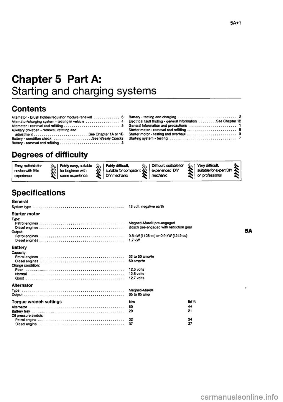
5A»1
Chapters Part A:
Starting and charging systems
Contents
Alternator - brush holder/regulator module renewal 6 Alternator/charging system • testing in vehicle 4 Alternator • removal and refitting 5 Auxiliary drivebelt • removal, refitting and adjustment See Chapter 1A or 1B Battery • condition check See Weekly Checks Battery • removal and refitting 3
Battery - testing and charging 2 Electrical fault finding • general Information See Chapter 12 General Information and precautions 1 Starter motor • removal and refitting 8 Starter motor - testing and overhaul 9 Starting system - testing 7
Degrees of difficulty
Easy, suitable for & novice with Tittle jg experience ^
Fairly easy, suitable ^ for beginner with some experience 3J
Fairly tfifftait, J^ sutable for competent ^ DIYmechanic ^
Difficult, suitable for ^ experienced D!Y mechanic ^
Verydtfficult, jk stitable far expert DfY X or professional ^
Specifications
General System type 12 volt, negative earth
Starter motor Type: Petrol engines Magneti-Marelli pre-engaged Diesel engines Bosch pre-engaged with reduction gear Output: 5A Petrol engines 0.8 kW (1108 cc) or 0.9 kW (1242 cc) Diesel engines 1.7 kW
Battery Capacity: Petrol engines 32 to 50 amp/hr Diesel engines 60 amp/hr Charge condition: Poor 12.5 volts Normal 12.6 volts Good 12.7 volts
Alternator Type Magneti-Marelli Output 65 to 85 amp
Torque wrench settings Nm ibt ft Alternator 60 44 Battery tray 29 21 Oil pressure switch: Petrol engine 32 24 Diesel engine 37 27
Page 153 of 225
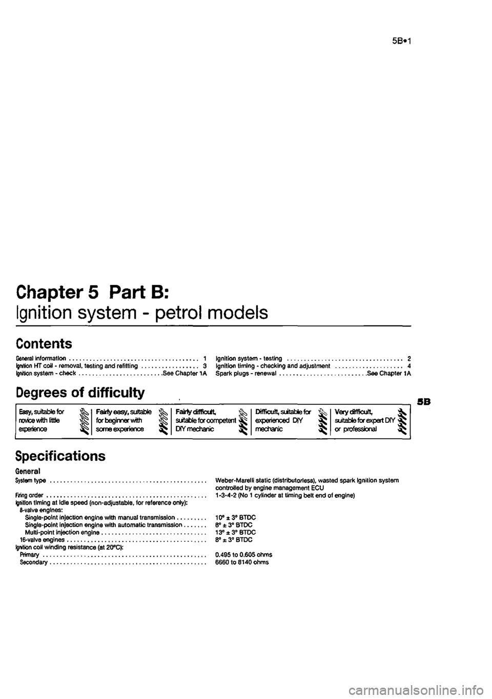
5B*1
Chapters PartB:
Ignition system - petrol models
Contents
General information 1 Ignition system - testing 2 Ignriton HT coil - removal, testing and refitting 3 Ignition timing - checking and adjustment 4 Igrrtion system - check See Chapter 1A Spark plugs - renewal See Chapter 1A
Degrees of difficulty
Easy,
suitable for Falrty easy, sulabte Fafety difficult, suitable for competent Difficult, suitable for Very difficult, ^ novice with littie
1
for beginner with Fafety difficult, suitable for competent experienced DIY suitable for expert DIY or professional ^ expenence 1 some experience DIY mechanic mechanic *
suitable for expert DIY or professional ^
Specifications
General System type
firing order Ignition timing at Idle speed (non-adjustable, for reference onlyy. 6-valve engines: Single-point injection engine with manual transmission .... Single-point injection engine with automatic transmission.. Multi-point injection engine 16-valve engines
Ignition
coil winding resistance (at 20°C): Primary Secondary
Weber-Marelli static (distributorless), wasted spark Ignition system controlled by engine management ECU
1
-3-4-2 (No 1 cylinder at timing belt end of engine)
10® ± 3° BTDC 6° ± 3° STDC 13° ±3° BTDC 8° x 3° BTDC
0.495 to 0.605 ohms 6660 to 8140 Ohms
Page 154 of 225
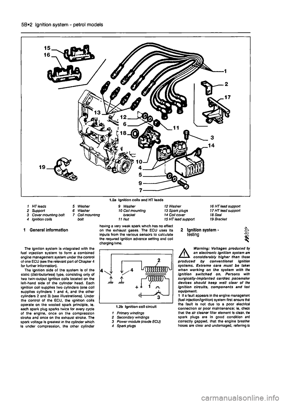
5B*2 Ignition system - petrol models
1 HT leads 2 Support 3 Cover mounting bdt 4 Ignition coifs
5 Washer 6 Washer 7 Coil mounting bolt
1.2s Ignition coils and HT leads 9 Washer 10 Coil mounting bracket
11
Nut
12 Waslrer 13 Spark plugs 14 Coll cover 15 HT lead support
16 HT lead support 17HTlead support 18 Seat Id Bracket
1 General information
The ignition system is integrated with the fuel injection system to form a combined engine management system under the control of one ECU (see the relevant part of Chapter 4 lor further Information). The Ignition side of the system is of the static (distributorless) type, consisting only of two twin-output Ignition coils located on the left-hand side of the cylinder head. Each ignition coil supplies two cylinders (one coll supplies cylinders 1 and 4, and the other cylinders 2 and 3) (see Illustrations). Under the control of the ECU, the ignition coils operate on the wasted spark principle, ie. each spark plug sparks twice for every cycle of the engine, once on the compression stroke and once on tho exhaust stroke. The spark voltage is greatest in the cylinder which Is under compression, the other cylinder
having a very weak spark which has no effect on the exhaust gases. The ECU uses Its Inputs from the various sensors to calculate the required ignition advance setting and coil chorging time.
1.2b Ignition coll circuit 1 Primary windings 2 Secondary windings 3 Power module
2 Ignition system -testing i
A
Warning: Voltages produced
by
an electronic Ignition system an considerably higher than (hose produced by conventional Ignition systems. Extreme care must be tak»n when working on tho system with thi Ignition switched on. Persons wilfl surgically-implanted cardiac pacemaker devices should keep well clear ot the ignition circuits, components and (oaf equipment 1 If a fault appears In the engine management (fuel injection/ignition) system first ensure that the fault is not due to a poor electrical connection or poor maintenance: ie, checK lhat the air cleaner filter element is clean, tht spark plugs are In good condition and correctly gapped, lhat the engine breather hoses are clear and undamaged, referring to
Page 155 of 225
Ignition system - petrol models 5B®3
Chapter 1A tor further information. Also check tnat tha accelerator cable is correctly adjusted
as
described in the relevant part of Chapter 4. If the engine is running very roughly, check the compression pressures and the valve clearances as descnbed In the relevant parts of Chapters 1 and 2. 2
H
these checks fall to reveal the cause of the problem, the vehicle should be taken to a suitably equipped Fiat dealer for testing. A wiring block connector Is Incorporated in the engine management circuit Into which a special electronic diagnostic tester can be plugged. The tester will locate the fault quickly and simply alleviating the need to test all the system components Individually which is a time consuming operation that carries a high risk of damaging the ECU. 3 The only Ignition system checks which can
oe
earned out by the home mechanic are those cescribed in Chapter 1A, relating to the spark plugs, and the ignition coll test descnbed In this Chapter. If necessary, the system wiring and wiring connectors can oe checked as descnbed in Chapter 12, Section 2, ensuring that the ECU wiring connector(s) have first
been
disconnected.
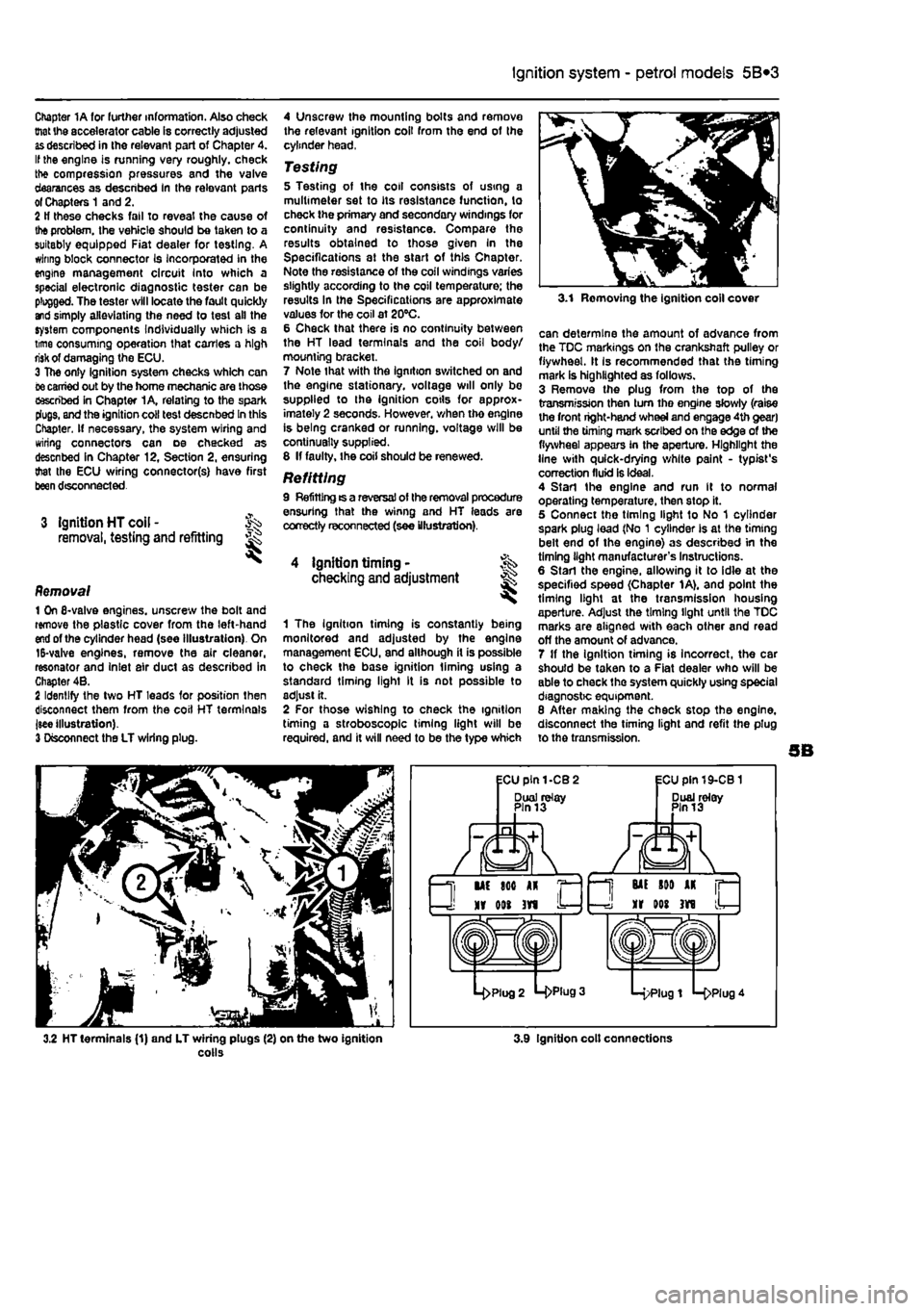
3 Ignition HT coil - ^ removal, testing and refitting
Removal 1 On 6-valve engines, unscrew the boll and remove the plastic cover from the left-hand
end
of the cylinder head (see Illustration). On 15-valve engines, remove the air cleaner, resonator and Inlet air duct as described in Chapter 4B. 2 Identify the two HT leads for position then disconnect them from the coil HT terminals jsee illustration). 3 Disconnect the LT wiring plug.
4 Unscrew the mounting bolts and remove the relevant ignition coil from the end of the cylinder head,
Testing 5 Testing of the coil consists of using a multimeter set to its resistance function, to check the primary and secondary windings for continuity and resistance. Compare the results obtained to those given In the Specifications at the start of this Chapter. Note the resistance of the coil windings varies slightly according to the coil temperature; the results In the Specifications are approximate values for the coil at 20°C. 6 Check that there is no continuity between the HT lead terminals and the coil body/ mourning bracket. 7 Note that with the ignition switched on and the engine stationary, voltage will only be supplied to the ignition cotls for approx-imately 2 seconds. However, when tho engine is being cranked or running, voltage will be continually supplied. 8 If faulty, the coil should be renewed.
Refitting 9 Refitting ts a reversal of the removal procedure ensuring that the winng and HT leads are correctly reconnected (see illustration).
4 ignition timing • checking and adjustment
1 The Ignition timing is constantly being monitored and adjusted by the engine management ECU, and although it is possible to check the base ignition liming using a standard timing light It is not possible to adjust it. 2 For those wishing to check the ignition timing a stroboscope timing light will be required, and it will need to be the type which
3.1 Removing the ignition coll cover
can determine the amount of advance from the TDC markings on the crankshaft pulley or flywheel. It Is recommended that the timing mark is highlighted as follows. 3 Remove the plug from the top of the transmission then turn tho engine slowly (raise the front right-hand wheel and engage 4th gear) until the timing mark scribed on the edge of the flywheel appears in the aperture. Highlight the line with quick-drying white paint - typist's correction fluid is ideal. 4 Start the engine and run It to normal operating temperature, then stop it. 5 Connect the timing light to No 1 cylinder spark plug lead (No 1 cylinder Is at the timing belt end of the engine) as described in the timing light manufacturer's Instructions. 6 Start the engine, allowing it to idle at the specified speed (Chapter 1A), and point the timing light at the transmission housing aperture. Adjust the timing light until the TDC marks are aligned with each other and read off the amount of advance. 7 If the ignition timing is incorrect, the car should be taken to a Fiat dealer who will be able to check the system quickly using special diagnostic equipment. 8 After making the check stop the engine, disconnect the timing light and refit the plug to the transmission.
3.2 HT terminals (1) and LT wiring plugs (2) on the two ignition colls 3.9 Ignition colt connections
Page 162 of 225
7A»1
Chapter 7 Part A:
Manual transmission
Contents
Gearchange lever and linkage - removal and refitting 2 General information 1 Manual transmission oil level check See Chapter 1A or 18 Manual transmission oil renewal See Chapter 1A or 1B
Manual transmission overhaul • general information 4 Manual transmission • removal and refitting 3 Reversing light switch • testing, removal and refitting 5
Degrees of difficulty
Easy, suitable
for Faiity
easy,
suitable FaMycffficult, ^ Difficult,
sutable fa-
Verycfifficutt, ^
novice with
little
1
for beginner with suitable
for
competent experienced DIY * * < siitable
for
expert
DIY
jR or professional ^ experience 1
some
experience DIYmechanic ^ mechanic * * < siitable
for
expert
DIY
jR or professional ^
Specifications
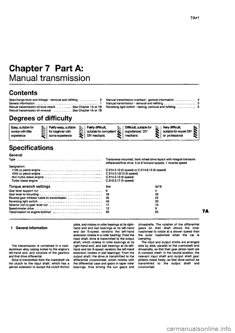
General Type
Designation: 1108 cc petrol engine 1242 cc petrol engine Non-turbo diesel engine Turbo diesel engine
Torque wrench settings Gear lever support nut Gear lever to mounting Reverse gear inhibitor cable to transmission Reversing light switch Selector rod-to-gear lever nut Speedometer drive Transmission-to-engine bolt/nut
Transverse mounted, front wheel drive layout with integral transaxle differential/final drive. 5 or 6 forward speeds, 1 reverse speed
C.S14.5.10 (5-speed) or C.514.6.10 (6-speed) C.514.5.1Q/13 (5-speed) C.514.5.13 (5-speed) C.510.5.17 (5-speed)
Nm Ibftl 6 4 49 36 30 22 40 30 17 13 12 9 es 63
1 Genera) Information
The transmission is contained In a cast-aluminium alloy casing bolted to the engine's left-hand end, and consists of the gearbox end final drive differential, Drive Is transmitted from the crankshaft via the clutch to the Input shaft, which has a spiined extension to accept the clutch friction
plate, and rotates in roller bearings at its right-hand end and ball bearings at its left-hand end (on 6-speed versions the left-hand extension rotates In a roller bearing). From the input shaft, drive is transmitted to tho output shaft, which rotates In roller bearings at Its right-hand end. and ball bearings at its left* hand end (on 6-speed versions the left-hand extension rotates in ball bearings). From the output shaft, the drive is transmitted to the differential crownwheel, which rotates with the differential case and gears in taper roller bearings, thus driving the sun gears and
driveshafts. The rotation of the differential gears on their shaft allows the inner roadwheel to rotate at a slower speed than the outer roadwheel when the car is cornering. The Input and output shaftB are arranged side by side, parallel to the crankshaft and driveshafts, so that their gear pinion teeth are In constant mesh. In the neutral position, the relevant input shaft and output shaft gear pinions rotate freely, so that drive cannot be transmitted to the output shaft and crownwheel.
Page 166 of 225
7B«1
Chapter 7 Part B:
Automatic transmission
Contents
Accelerator pedal micro-switch(es) - checking and adjustment II Automatic transmission filter and fluid change See Chapter 1A Automatic transmission fluid level check See Weekly checks Automatic transmission • overhaul 12 Automatic transmission • removal and refining 2 Bectro-magnetic clutch - removal, inspection and refitting 3 BectrO'fnagnetic clutch brushes- removal, inspection and refitting . 4
Electronic control unit - removal and refitting 5 Gear selector cable - adjustment 6 Gear selector cable - removal and refitting 9 General information 1 Kickdown cable - adjustment 7 Kickdown cable - removal and refitting 6 Transmission oil pump - removal and refitting 10
Degrees of difficulty
Easy,
suitable for novice
with
ittle experience ^
Party
easy,
suitable for beginner
with
^r someexperienoe ^
Faiily
difficult,
^ suitable
for
competent
DIY mechanic
^
Difficult, suitable
for fe, experienced DIY >8J mechanic
Verydfficult, ^
suitable
for
expert DIY
or professional ^
Specifications
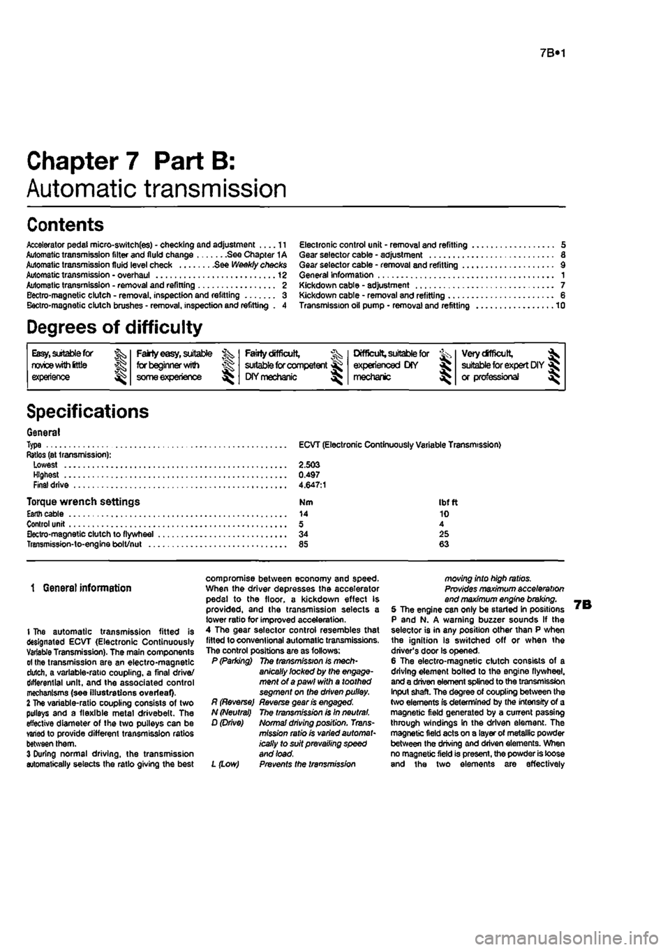
General Type Ratios (at transmission): Lowest Highest Final drive
Torque wrench settings Esnh cable Control unit Sectro-magnetic clutch to flywheel Transmission-to-engine bolt/nut ..
ECVT (Electronic Continuously Variable Transmission)
2.503 0.497 4.647:1
Nm Ibftt 14 10 5 4 34 25 85 63
1 Genera) information
I The automatic transmission fitted is designated ECVT (Electronic Continuously Variable Transmission). The main components
01
the transmission are an electro-magnetic dutch, a variable-ratio coupling, a final drive/ differential unit, and the associated control mechanisms (see illustrations overleaf) 2 The variable-ratio coupling consists of two pulleys and a flexible metal drivebelt. The effective diameter of the two pulleys can be varied to provide different transmission ratios between them. 3 During normal driving, the transmission automatically selects the ratio giving the best
compromise between economy and speed. When the driver depresses the accelerator pedal to the floor, a kickdown effect is provided, and the transmission selects a lower ratio for improved acceleration. 4 The gear selector control resembles that fitted to conventional automatic transmissions. The control positions are as follows: P (Parking) The transmission is mech-anically locked by the engage-ment of a pawl with a toothed segment on the driven pulley. R (Reverse) Reverse gean's engaged, N (Neutral) The transmission is In neutral. D (Drive) Normal driving position. Trans-mission ratio is varied automat-ically to suit prevailing speed and load.
L (Low) Prevents the transmission
moving into high ratios. Provides maximum acceleration end maximum engine braking. 5 The engine can only be started In positions P and N. A warning buzzer sounds If the selector is in any position other than P when the ignition is switched off or when the driver's door is opened. 6 The electro-magnetic clutch consists of a driving element boiled to the engine flywheel, and a driven element spiined to the transmission Input shaft. The degree of coupling between the (wo elements Is determined by the intensity of a magnetic field generated by a current passing through windings in the driven element. The magnetic field acts on a layer of metallic powder between the driving and driven elements. When no magnetic field is present, the powder is loose and the two elements are effectively
Page 177 of 225
9«1
Chapter 9
Braking system
Contents
Brake disc - inspection, removal and refitting 4 Brake fluid level check See Weekly checks Brake fluid renewal See Chapter 1A or 1B Brake warning lamp check See Chapter 1A or 1B Front brake caliper - removal, overhaul and refitting 3 Front brake pad check See Chapter 1A or 1B Front brake pads - renewal 2 General information 1 Handbrake - checking and adjustment 9
Handbrake cables - removal and refitting 10 Hydraulic pipes end hoses - renewal 13 Hydraulic system - bleeding 11 Master cylinder - removal and refitting 12 Roar brake shoe check See Chapter 1A or 1B Rear brake shoes - renewal 5 Rear brake drums - removal, inspection and refitting 6 Rear wheel cylinder - removal, overhaul and refitting 7 Stop-light switch - adjustment, removal and refitting 6
Degrees of difficulty
Easy, suitable
far
novice with Sttle
experience ^
Fairly
easy,
suitable ^ (orbeginnerwith ®
some
experience
Fairly difficult, suitable
for
compe«ent ^ CHYmechanlc ^
Difficult, suitable for
experienced DIY « mechanic ^
Very difficult, ^
suitable
for
expert DIY
or professional ^
Specifications
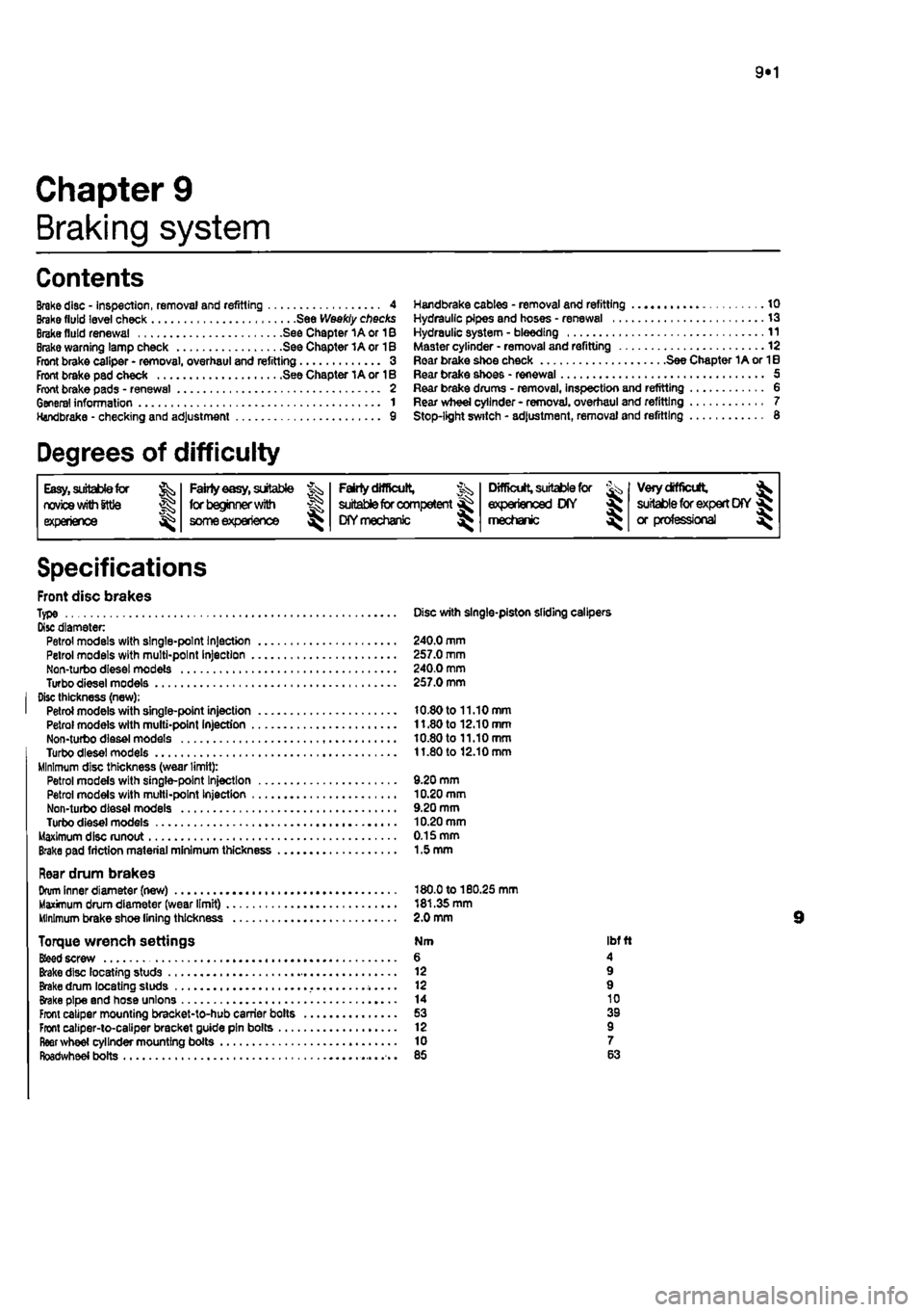
Front disc brakes Type Disc with single-piston sliding calipers Disc diameter Petrol models with single-point Injection 240.0 mm Petrol models with multi-point Injection 257.0 mm Non-turbo diesel models 240.0 mm Turbodieselmodels 257.0 mm Disc thickness (new); Petrol models with single-point injection 10.80 to 11.10 mm Petrol models with multi-point Injection 11.80 to 12.10 mm Non-turbo diesel models 10.80 to 11.10 mm Turbodieselmodels 11.80 to 12.10 mm Minimum disc thickness (wear limit): Petrol models with single-pant Injection 9.20 mm Petrol models with multi-point Injection 10.20 mm Non-turbo diesel models 9.20 mm Turbo diesel models 10.20 mm Maximum disc runout 0.15 mm Brake pad friction material minimum thickness 1.5 mm
Rear drum brakes Drum Inner diameter (new) 180.0 to 180.25 mm Maximum drum diameter (wear limit) 181.35 mm Minimum brake shoe lining thickness 2.0 mm
Torque wrench settings Nm ibf ft
Bfeed
screw 6 4 Brake disc locating studs 12 9 Brake drum locating studs 12 9 Brake pipe and hose unions 14 10 Front caliper mounting bracket-to-hub carrier bolts 53 39 Front caliper-to-caliper bracket guide pin bolts 12 9 fleer wheel cylinder mounting boils 10 7 Roadwheel bolts 85 63
Page 186 of 225
9*10 Braking system
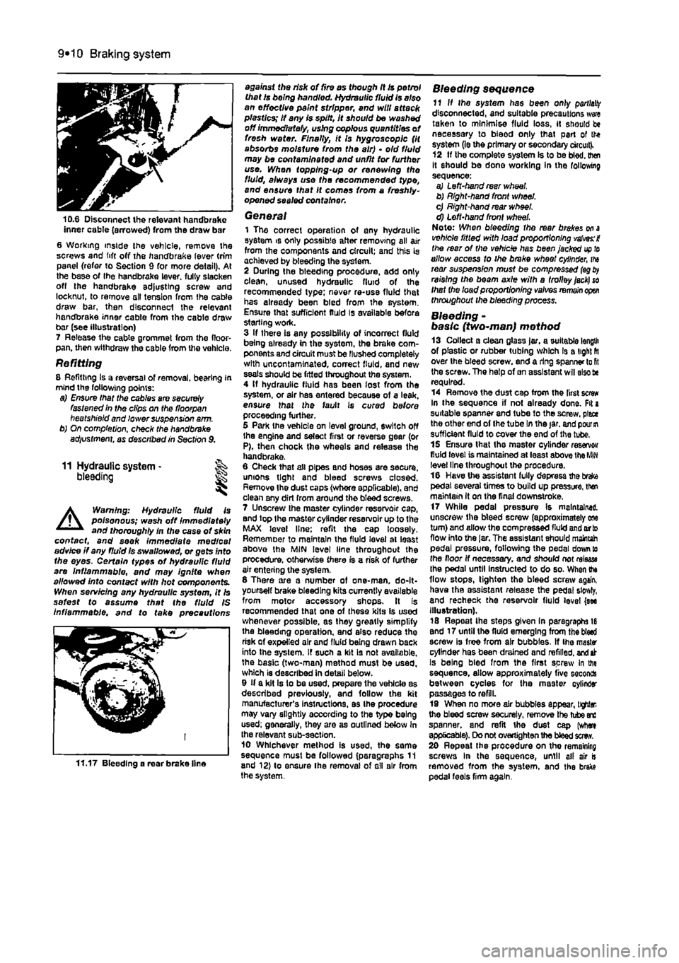
10.6 Disconnect the relevant handbrake inner cable (arrowed) from the draw bar 6 Working inside ihe vehicle, remove Ihe screws and lift off the handbrake lever trim panel (refer to Section 9 for more detail). At the base of the handbrake lever, full/ slacken off the handbrake adjusting screw and locknut, to remove oil tension from the cable draw bar, then disconnect the relevant handbrake inner cable from the cable draw bar (see illustration) 7 Release the cable grommet from tho floor-pan, then withdraw the cable from the vehicle.
Refitting 8 Refitting Is a reversal of removal, bearing in mind the following points: a) Ensure that the cables are securely fastened In the clips on the floorpan beetshield and lower suspension a/m. b) On completion, check the handbrake adiustment, as described in Section 9.
11 Hydraulic system -bleeding
A
Warning: Hydraulic fluid is poisonous; wash off immediately and thoroughly In the case ot skin contact, and seek immediate medical advice if any fluid is swallowed, or gets into the eyes. Certain types of hydraulic fluid are Inflammable, and may ignite when allowed into contact with hot components. When servicing any hydraulic system, it Is safest to assume that the fluid IS inflammable, and to take precautions
11.17 Bleeding a rear brake line
against the risk of fire as though it is petrol that Is being handled. Hydraulic fluid is also an effective paint stripper, and will attack plastics; If any is spilt, It should be washed off immediately, using copious quantities of fresh water. Finally, it Is hygroscopic (it absorbs moisture from the air) • old fluid may be contaminated and unfit tor further use. Whan topping-up or renewing the fluid, always use the recommended type, and ensure that It comes from a freshly-opened sealed container.
General 1 The correct operation of any hydraulic system is only possible after removing all air from the components and circuit; and this Is achieved by bleeding the syslem. 2 During the bleeding procedure, add only clean, unused hydraulic fluid of the recommended type; never re-use fluid that has already been bled from the system. Ensure that sufficient fluid is available before starting work. 3 If there is any possibility of incorrect fluid being already in the system, the brake com-ponents and circuit must be Flushed completely with uncontamlnated, correct fluid, and new seals should be fitted throughout the system. 4 If hydraulic fluid has been lost from the system, or air has ontered because of a leak, ensure that the fault is cured before proceeding further. 5 Park Ihe vehicle on level ground, switch off the engine and select first or reverse gear (or P), then chock the wheels and release the handbrake. 6 Cheek that all pipes and hoses are secure, unions tight and bleed screws closed. Remove Ihe dust caps (whore applicable), and clean any dirt from around the bleed screws. 7 Unscrew the master cylinder reservoir cap, and top Ihe master cylinder reservoir up to the MAX level line; refit the cap loosely. Rememoer to maintain the fluid level at least above the MIN level line throughout the procedure, otherwise there is a risk of further air entering the syslem. 8 There are a number of one-man. do-It-yourself brake bleeding kits currently available from motor accessory shops. It is recommended that one of these kits is used whenever possible, as they greatly simplify the bleeding operation, and also reduce the risk of expelled air and fluid being drawn back into the system. If such a kit is not available, the basic (two-man) method must be used, which is described in detail below. 9 If a kit Is to be used, prepare the vehicle as described previously, and follow the kit manufacturer's instructions, as Ihe procedure may vary slightly according to the type being used; generally, they are as outlined below in the relevant sub-section. 10 Whichever method is used, the same sequence must be followed (paragraphs 11 and 12) to ensure Ihe removal of all air from the system.
Bleeding sequence 11 If Ihe system has been only
partial!?
disconnected, and suitable precautions wwe taken to minimise fluid loss, it should be necessary to bteod only that part of the system (le the primary or secondary circuit). 12 If the complete system Is to be bled, then It should be done working in the following sequence: a) Left-hand rear wheel b) Right-hand front wheel. c) Right-hand rear wheel. d) Left-hand front wheel. Note: When bleeding the rear brakes
on a
vehicle ritled with load proportioning valves: i the rear of the vehicle has been jacked
up to
allow access to ihe brake wheel cylinder,
tha
rear suspension must be compressed
(eg
raising the beam axle with a trolley
jack) so
that the load proportioning valves
remain open
throughout the bleeding process.
Bleeding -basic (two~man) method 13 Collect a clean glass jar, a suitable length of plastic or rubber tubing which Is a light fit over the bleed screw, end a ring spanner lo
Rt
the screw. The help of an assistant will also tie required. 14 Remove the dust cap from the first screw In the sequence if not already done. Fit a suitable spanner and tube to the screw, place the other end of Ihe tube In the jar. and
pour in
sufficient fluid to cover the end of the tube. 15 Ensure that the master cylinder reservoir fluid level is maintained at least above the
MIN
level line throughout the procedure. 16 Have the assistant fully depress the brefce pedal several times to build up pressure, then maintain it on the final downstroke. 17 While pedal pressure is maintained, unscrew ihe bleed screw (approximately one turn) and allow the compressed fluid and orto flow into the
Jar,
The assistant should maintah pedal pressure, following the pedal down to the floor if necessary, and should not rrtaase Ihe pedal until instructed to do so. When ihe flow stops, tighten the bleed screw again, have the assistant retease the pedal sfowty, and recheck the reservoir fluid level (see Illustration). 18 Repeat Ihe steps given in paragraphs 16 end 17 until the fluid emerging from the bled screw is free from air bubbles. If Ihe master cylinder has been drained and refilled,
and
at Is being bled from the first screw In the sequence, allow approximately five seconds between cycles for the master cylinder passages to refill. 19 When no more air bubbles appear, tighter, the bleed screw securely, remove Ihe tube arc spanner, and refit the dust cap (where applicable). Do not overtighten the bleed sew. 20 Repeat the procedure on tho remaining screws In the sequence, until ail air is removed from the system, and the brake pedal feels firm again.
Page 189 of 225
10*1
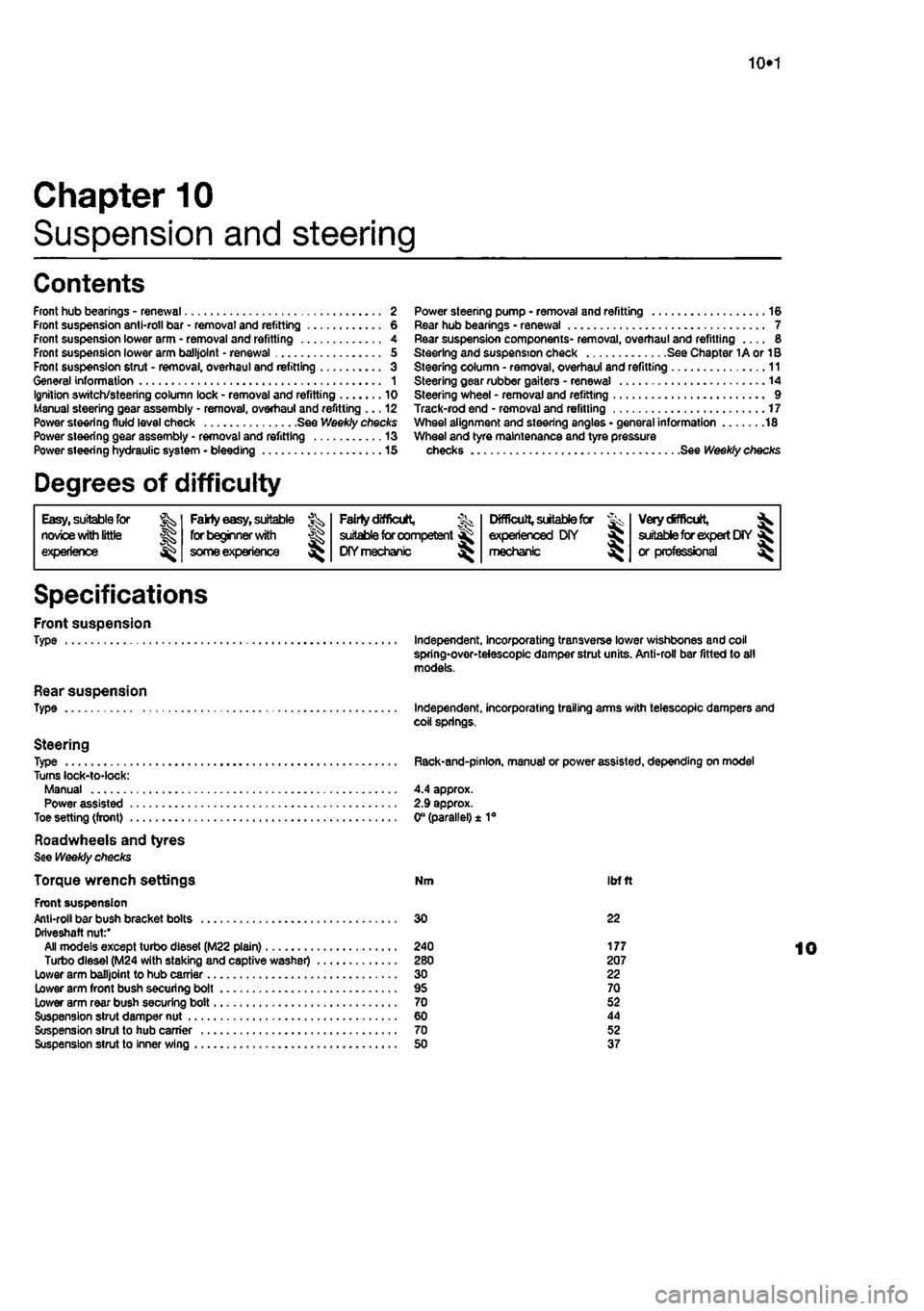
Chapter 10
Suspension and steering
Contents
Front hub bearings - renewal 2 Front suspension anti-roll bar • removal and refitting 6 Front suspension lower arm - removal and refitting 4 Front suspension lower arm balljolnt - renewal 5 From suspension strut - removal, overhaul and refitting 3 General information 1 Ignition switch/steering column lock - removal and refitting 10 Manual steering gear assembly - removal, overhaul and refitting ... 12 Power steering fluid level check See Weekly checks Power steering gear assembly - removal and refitting 13 Power steering hydraulic system - bleeding 15
Degrees of difficulty
Power steering pump • removal and refitting 16 Rear hub bearings - renewal 7 Rear suspension components- removal, overhaul and refitting 8 Steering and suspension check See Chapter 1A or 1B Steering column - removal, overhaul and refitting 11 Steering gear rubber gaiters - renewal 14 Steering wheel - removal and refitting 9 Track-rod end - removal and refitting 17 Wheel alignment and steering angles • general information 18 Wheel and tyre maintenance and tyre pressure checks See Weekly checks
Easy, suitable for nowoe with little
Jg experience ^
Fakty easy,
suitable for beginner
with
J£>
some experience
^
FaMy difficult,
% suitable for competent ^
DIY mechanic
^
Difficult,
suitable for & experienced DIY « mechsmc ^
Very difficult,
^ suitable for expert
DIY
fij or professional ^
Specifications
Front suspension Type
Rear suspension Type
Steering Type Turns lock-to-lock: Manual Power assisted Toe setting (front)
Roadwheeis and tyres See Weekly checks
Torque wrench settings Front suspension Anti-roll bar bush bracket bolts Driveshaft nut:' All models except turbo diesel (M22 plain) Turbo diesel (M24 with staking and captive washer) Lower arm balljoint to hub carrier Lower arm front bush securing bolt Lower arm rear bush securing bolt Suspension strut damper nut Suspension strut to hub carrier Suspension strut to inner wing
Independent, incorporating transverse lower wishbones and coil spring-over-teiescopic damper strut units. Anti-roll bar fitted to all models.
Independent, incorporating trailing arms with telescopic dampers and coil springs.
Rack-and-pinlon, manual or power assisted, depending on model
4.4 approx. 2.9 approx. 0° (parallel) ± 1a
Nm ibfft
30 22
240 177 280 207 30 22 95 70 70 52 60 44 70 52 50 37
Page 204 of 225
Bodywork and fittings
11
*3
several blobs of filler paste around its periphery. Aluminium tape should be used for small or very narrow holes. Pull a piece off the roll, trim it to the approximate size and shape required, then pull off the backing paper (if used) and stick the tape over the hole; it can be overlapped if the thickness of one piece is Insufficient. Burnish down the edges of the tape with the handle of a screwdriver or similar, to ensure that the tape is securely attached to the metal underneath.
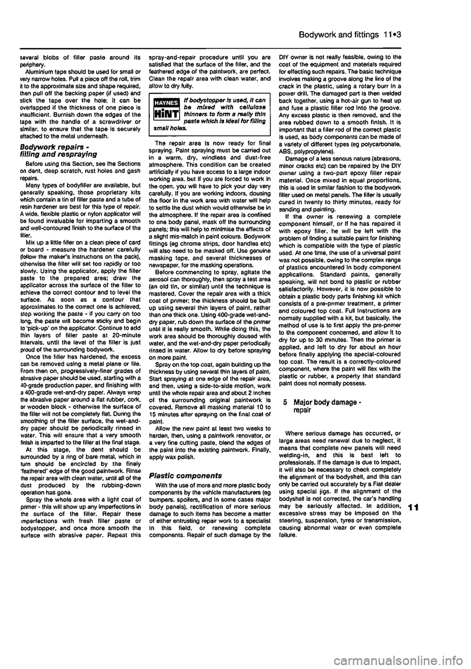
Bodywork repairs -filling and respraying Before using this Section, see the Sections on dent, deep scratch, rust holes and gash repairs. Many types of bodyfiller are available, but generally speaking, those proprietary kits which contain a tin of filler paste and a tube of resin hardener are best for this type of repair. A wide, flexible plastic or nylon applicator will be found invaluable for imparting a smooth and well-contoured finish to the surface of the filler. Mix up a little filler on a clean piece of card or board • measure the hardener carefully (follow the maker's instructions on the pack), otherwise the filler will set too rapidly or too slowly. U3ing the applicator, apply the filler paste to the prepared area; draw the applicator across the surface of the filler to achieve the correct contour and to level the surface. As soon as a contour that approximates to the correct one is achieved, stop working the paste - if you carry on too long, the paste will become sticky and begin lo 'pick-up' on the applicator. Continue to add thin layers of filler paste at 20-minute Intervals, until the level of the filler is just proud of the surrounding bodywork. Once the filler has hardened, the excess can be removed using a metal plane or file. From then on, progressively-finer grades of abrasive paper should be used, starting with a 40-grade production paper, and finishing with a 400-grade wet-and-dry paper. Always wrap the abrasive paper around a flat rubber, cork, or wooden block • otherwise the surface of the filler will not be completely flat. During the smoothing of the filler surface, the wet-and-dry paper should be periodically rinsed in water. This will ensure that a very smooth finish is imparled to the filler at the final stage. At this stage, the dent should be surrounded by a ring of bare metal, which in turn should be encircled by the finely feathered' edge of the good paintwork. Rinse the repair area with clean water, until all of the dust produced by the rubbing-down operation has gone. Spray the whole area with a light coat of primer - this will show up any imperfections In the surface of the filler. Repair these imperfections with fresh filler paste or bodystopper, and once more smooth the surface with abrasive paper. Repeat this
spray-and-repair procedure until you are satisfied that the surface of the filler, and the feathered edge of the paintwork, are perfect. Clean the repair area with clean water, and allow to dry fully.
flflfl^gl tf txxfystopper is used, it can WiMiiBi be mixed with cellulose Hi NT thinners to form a really thin 1 1 paste which is Ideal for filling small holes.
The repair area Is now ready for final spraying. Paint spraying must be carried out in a warm, dry, windless and dust-free atmosphere. This condition can be created artificially if you have access to a large indoor working area, but If you are forced to work in the open, you will have to pick your day very carefully. If you are working indoors, dousing the floor In the work area with water will help to settle the dust which would otherwise be in the atmosphere. If the repair area is confined to one body panel, mask off the surrounding panels; this will help to minimise the effects of a slight mis-match in paint colours. Bodywork fittings (eg chrome strips, door handles etc) will also need to be masked off. Use genuine masking tape, and several thicknesses of newspaper, for the masking operations. Before commencing to spray, agitate the aerosol can thoroughly, then spray a test area (an old tin. or similar) until the technique is mastered. Cover the repair area with a thick coat of primer; the thickness should be built up using several thin layers of paint, rather than one thick one. Using 400-grade wet-and-dry paper, rub down the surface of the pnmer until it is really smooth. While doing this, the work area should be thoroughly doused with water, and the wet-and-dry paper periodically rinsed in water. Allow to dry before spraying on more paint. Spray on the top coat, again building up the thickness by using several thin layers of paint. Start spraying at one edge of the repair area, and then, using a side-to-side motion, work until the whole repair area and about 2 inches of the surrounding original paintwork is covered. Remove all masking material 10 to 15 minutes after spraying on the final coat of paint. Allow the new paint at least two weeks to harden, then, using a paintwork renovator, or a very fine cutting paste, blend the edges of the paint into the existing paintwork. Finally, apply wax polish.
Plastic components With the use of more and more plastic body components by the vehicle manufacturers (eg bumpers, spoilers, and in some cases major body panels), rectification of more serious damage to such items has become a matter of either entrusting repair work to a specialist in this field, or renewing complete components. Repair of such damage by the
DIY owner is not really feasible, owing to the cost of the equipment and materials required for effecting such repairs. The basic technique involves making a groove along the line of the crack in the plastic, using a rotary burr In a power drill. The damaged part is then welded back together, using a hot-air gun to heat up and fuse a plastic filler rod Into the groove. Any excess plastic is then removed, and the area rubbed down to a smooth finish. It is important that a filler rod of the correct plastic is used, as body components can be made of a variety of different types (eg polycarbonate, ABS, polypropylene). Damage of a less senous nature (abrasions, minor cracks etc) can be repaired by the DIY owner using a two-part epoxy filler repair material. Once mixed in equal proportions, this is used in similar fashion to the bodywork filler used on metal panels. The filler is usually cured in twenty to thirty minutes, ready for sanding and painting. If the owner is renewing a complete component himself, or If he has repaired it with epoxy filler, he will be left with the problem of finding a suitable paint for finishing which is compatible with the type of plastic used. At one time, the use of a universal paint was not possible, owing to the complex range of plastics encountered In body component applications. Standard paints, generally speaking, will not bond to plastic or rubber satisfactorily. However, it is now possible to obtain a plastic body parts finishing kit which consists of a pre-pnmer treatment, a primer and coloured top coat. Full Instructions are normally supplied with a kit, but basically, the method of use is to first apply the pre-pnmer to the component concerned, and allow It to dry for up to 30 minutes. Then the primer is applied, and left to dry for about an hour before finally applying the special-coloured top coat. The result is a correctly-coloured component, where the paint will flex with the plastic or rubber, a property that standard paint does not normally possess.
5 Major body damage -repair
Where serious damage has occurred, or large areas need renewal due to neglect, it means that complete new panels will need welding-in, and this is best left to professionals. If the damage is due to Impact, it will also be necessary to check completely the alignment of the bodyshell, and this can only be carried out accurately by a Fiat dealer using special jigs. If the alignment of the bodyshell is not corrected, the car's handling may be seriously affected. In addition, excessive stress may be Imposed on the steering, suspension, tyres or transmission, causing abnormal wear or even complete failure.