stop start FIAT PUNTO 1994 176 / 1.G Owner's Manual
[x] Cancel search | Manufacturer: FIAT, Model Year: 1994, Model line: PUNTO, Model: FIAT PUNTO 1994 176 / 1.GPages: 225, PDF Size: 18.54 MB
Page 204 of 225

Bodywork and fittings
11
*3
several blobs of filler paste around its periphery. Aluminium tape should be used for small or very narrow holes. Pull a piece off the roll, trim it to the approximate size and shape required, then pull off the backing paper (if used) and stick the tape over the hole; it can be overlapped if the thickness of one piece is Insufficient. Burnish down the edges of the tape with the handle of a screwdriver or similar, to ensure that the tape is securely attached to the metal underneath.
Bodywork repairs -filling and respraying Before using this Section, see the Sections on dent, deep scratch, rust holes and gash repairs. Many types of bodyfiller are available, but generally speaking, those proprietary kits which contain a tin of filler paste and a tube of resin hardener are best for this type of repair. A wide, flexible plastic or nylon applicator will be found invaluable for imparting a smooth and well-contoured finish to the surface of the filler. Mix up a little filler on a clean piece of card or board • measure the hardener carefully (follow the maker's instructions on the pack), otherwise the filler will set too rapidly or too slowly. U3ing the applicator, apply the filler paste to the prepared area; draw the applicator across the surface of the filler to achieve the correct contour and to level the surface. As soon as a contour that approximates to the correct one is achieved, stop working the paste - if you carry on too long, the paste will become sticky and begin lo 'pick-up' on the applicator. Continue to add thin layers of filler paste at 20-minute Intervals, until the level of the filler is just proud of the surrounding bodywork. Once the filler has hardened, the excess can be removed using a metal plane or file. From then on, progressively-finer grades of abrasive paper should be used, starting with a 40-grade production paper, and finishing with a 400-grade wet-and-dry paper. Always wrap the abrasive paper around a flat rubber, cork, or wooden block • otherwise the surface of the filler will not be completely flat. During the smoothing of the filler surface, the wet-and-dry paper should be periodically rinsed in water. This will ensure that a very smooth finish is imparled to the filler at the final stage. At this stage, the dent should be surrounded by a ring of bare metal, which in turn should be encircled by the finely feathered' edge of the good paintwork. Rinse the repair area with clean water, until all of the dust produced by the rubbing-down operation has gone. Spray the whole area with a light coat of primer - this will show up any imperfections In the surface of the filler. Repair these imperfections with fresh filler paste or bodystopper, and once more smooth the surface with abrasive paper. Repeat this
spray-and-repair procedure until you are satisfied that the surface of the filler, and the feathered edge of the paintwork, are perfect. Clean the repair area with clean water, and allow to dry fully.
flflfl^gl tf txxfystopper is used, it can WiMiiBi be mixed with cellulose Hi NT thinners to form a really thin 1 1 paste which is Ideal for filling small holes.
The repair area Is now ready for final spraying. Paint spraying must be carried out in a warm, dry, windless and dust-free atmosphere. This condition can be created artificially if you have access to a large indoor working area, but If you are forced to work in the open, you will have to pick your day very carefully. If you are working indoors, dousing the floor In the work area with water will help to settle the dust which would otherwise be in the atmosphere. If the repair area is confined to one body panel, mask off the surrounding panels; this will help to minimise the effects of a slight mis-match in paint colours. Bodywork fittings (eg chrome strips, door handles etc) will also need to be masked off. Use genuine masking tape, and several thicknesses of newspaper, for the masking operations. Before commencing to spray, agitate the aerosol can thoroughly, then spray a test area (an old tin. or similar) until the technique is mastered. Cover the repair area with a thick coat of primer; the thickness should be built up using several thin layers of paint, rather than one thick one. Using 400-grade wet-and-dry paper, rub down the surface of the pnmer until it is really smooth. While doing this, the work area should be thoroughly doused with water, and the wet-and-dry paper periodically rinsed in water. Allow to dry before spraying on more paint. Spray on the top coat, again building up the thickness by using several thin layers of paint. Start spraying at one edge of the repair area, and then, using a side-to-side motion, work until the whole repair area and about 2 inches of the surrounding original paintwork is covered. Remove all masking material 10 to 15 minutes after spraying on the final coat of paint. Allow the new paint at least two weeks to harden, then, using a paintwork renovator, or a very fine cutting paste, blend the edges of the paint into the existing paintwork. Finally, apply wax polish.
Plastic components With the use of more and more plastic body components by the vehicle manufacturers (eg bumpers, spoilers, and in some cases major body panels), rectification of more serious damage to such items has become a matter of either entrusting repair work to a specialist in this field, or renewing complete components. Repair of such damage by the
DIY owner is not really feasible, owing to the cost of the equipment and materials required for effecting such repairs. The basic technique involves making a groove along the line of the crack in the plastic, using a rotary burr In a power drill. The damaged part is then welded back together, using a hot-air gun to heat up and fuse a plastic filler rod Into the groove. Any excess plastic is then removed, and the area rubbed down to a smooth finish. It is important that a filler rod of the correct plastic is used, as body components can be made of a variety of different types (eg polycarbonate, ABS, polypropylene). Damage of a less senous nature (abrasions, minor cracks etc) can be repaired by the DIY owner using a two-part epoxy filler repair material. Once mixed in equal proportions, this is used in similar fashion to the bodywork filler used on metal panels. The filler is usually cured in twenty to thirty minutes, ready for sanding and painting. If the owner is renewing a complete component himself, or If he has repaired it with epoxy filler, he will be left with the problem of finding a suitable paint for finishing which is compatible with the type of plastic used. At one time, the use of a universal paint was not possible, owing to the complex range of plastics encountered In body component applications. Standard paints, generally speaking, will not bond to plastic or rubber satisfactorily. However, it is now possible to obtain a plastic body parts finishing kit which consists of a pre-pnmer treatment, a primer and coloured top coat. Full Instructions are normally supplied with a kit, but basically, the method of use is to first apply the pre-pnmer to the component concerned, and allow It to dry for up to 30 minutes. Then the primer is applied, and left to dry for about an hour before finally applying the special-coloured top coat. The result is a correctly-coloured component, where the paint will flex with the plastic or rubber, a property that standard paint does not normally possess.
5 Major body damage -repair
Where serious damage has occurred, or large areas need renewal due to neglect, it means that complete new panels will need welding-in, and this is best left to professionals. If the damage is due to Impact, it will also be necessary to check completely the alignment of the bodyshell, and this can only be carried out accurately by a Fiat dealer using special jigs. If the alignment of the bodyshell is not corrected, the car's handling may be seriously affected. In addition, excessive stress may be Imposed on the steering, suspension, tyres or transmission, causing abnormal wear or even complete failure.
Page 214 of 225

10*1
Chapter 12
Body electrical systems
Contents
Bulbs (exterior lights) - renewal 4 Bulbs (interior lights) - renewal 5 Electrical fault finding - general information 2 Exterior light units - removal and refitting 6 Fuses and relays - general Information 3 General information and precautions 1 Headlight beam alignment • general Information 6 Horn • removal and refitting 9 Instrument panel - removal and refitting 7 Loudspeakers - removal and refitting 10
Degrees of difficulty
Radio aerial - removal and refitting 11 Radio/cassette player • removal and refitting 12 Speedometer drive cable - removal and refitting 13 Switches - removal end refitting 14 Tailgate wiper motor - removal and refitting 15 Windscreen wiper motor - removal and refitting 17 Windscreen/tailgate washer system components • removal and refitting 16 Wiper arm • removal and refitting 18
Easy,
statable for ^
novice with liffle
|| experience ^
Fairly
easy,
suitable for beginner with ^ some experience ^
Fabtycffficiit,
suitable
for competent ^
DIY
mechanic ^
Difficult, suitable for
^ experienced DIY JR mechanic
Very difficult,
A,
suitable
for
expert DIY
Sj or professional ^
Specifications
Bulb ratings Watts Headlights 60/55 Front long range driving light 55 Front fogllght 55 Front direction Indicator light 21 Front sidelight 5 Front direction indicator repeater light 5 Stop light 21 Tall light 5 Rear direction indicator light 21 Reversing light 21 near fogllght 21 Hear number plate light 5 Courtesy light 10 Map reading light 5
1 Genera! information and precautions
A
Warning: fie/Ore carrying out any work on the electrical system, read through the precautions given in Safety first! at the beginning of this manual, and in Chapter 8. The electrical system is of 12-volt negative earth type. Power for the lights and all electrical accessories is supplied by a lead/acid type battery, which is charged by the alternator. This Chapter covers repair and service procedures for the various electrical components not associated with the engine. Information on the battery, alternator and starter motor can be found in Chapter 5. It should be noted that, prior to working on any component In the electrical system, the
battery negative terminal should first be disconnected, to prevent the possibility of electrical short-circuits and/or fires. Caution: Before proceeding, refer to Disconnecting the battery In the Reference Section of this manual for further information.
2 Electrical fault finding-general information
Note: Refer to the precautions given In Safety first! and in Section 1 of this Chapter before starting work. The following tests relate to testing ot the main electrical circuits, and should not be used to test delicate electronic circuits (such as antHock braking systems), particularly where an electronic con fro/ module is used.
General 1 A typical electrical circuit consists of an electrical component, any switches, relays, motors, fuses, fusible links or circuit breakers related to that component, and the wiring and connectors which link the component to both the battery and the chassis. To help to pinpoint a problem in an electrical circuit, wiring diagrams are Included at the end of this manual. 2 Before attempting to diagnose an electrical fault, first study the appropriate wiring diagram, to obtain a more complete understanding of the components included In the particular circuit concerned. The possible sources of a fault can be narrowed down by noting whether other components related to the circuit are operating properly. If several components or circuits fait at one time, the problem Is likely to be related to a shared fuse or earth connection.
Page 219 of 225

12*6 Body electrical systems
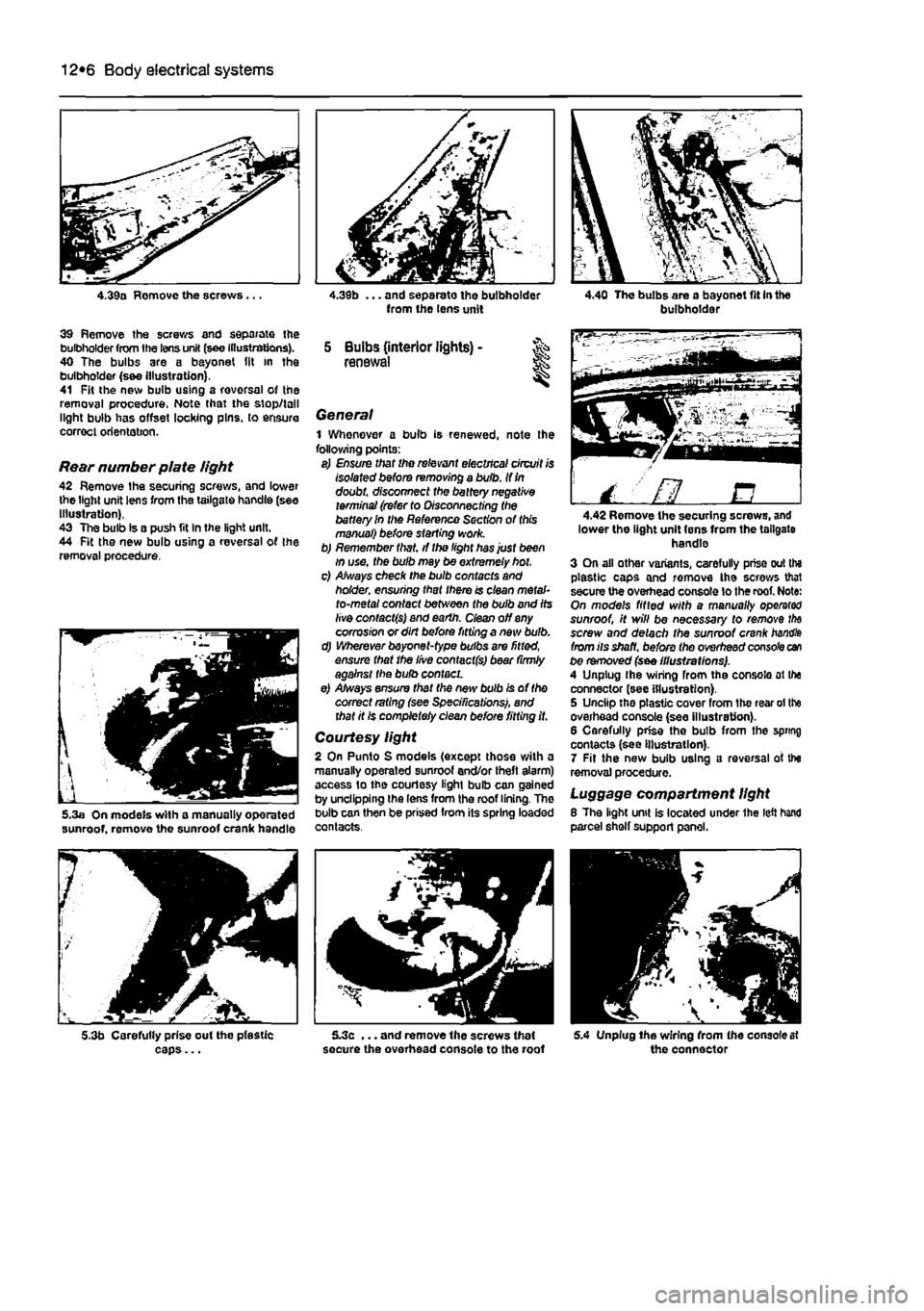
4.39a Remove the screws...
39 Remove the screws and separate the bulbholder from the lens unit (see Illustrations). 40 The bulbs are a bayonet (it in the bulbholder (s&e Illustration), 41 Fit the new bulb using a rovorsal of the removal procedure. Note that the stop/tall light bulb has offset locking pins, to ensure correct orientation.
Rear number plate light 42 Remove the securing screws, and lower the light unit lens from the tailgate handle (see Illustration), 43 The bulb Is a push fit In the light unit. 44 Fit the new bulb using a reversal of the removal procedure.
5.3a On models with a manually oporated sunroof, remove the sunroof crank handle
5.3b Carefully prise out the pfestic caps...
from the lens unit
5 Bulbs (interior lights) -renewal
General 1 Whenever a bulb is renewed, note Ihe following points: a) Ensure that the relevant electrical circuit is Isolated before removing a bulb. If
In
doubt, disconnect the battery negative terminal (refer to Disconnecting the battery In the Reference Section of this manual) before starting work. b) Remember that, if the light has just been in use, the bulb may be extremely hot. c) Always check the bulb contacts and holder, ensuring that there is clean metal-to-metal contact between the bulb and its live contacts) and earth, dean off any corrosion or dirt before fitting a new bulb. d) Wherever bayonet-type bulbs are fitted, ensure that the live contact(s) bear (irmly against the bulb contact. e) Always ensure that the new bulb is of the correct rating (see Specifications), and that it Is completely clean before fitting it.
Courtesy light 2 On Punto S models (except those with a manually operated sunroof end/or theft alarm) access to the courtesy light bulb can gained by unclipping the lens from the roof lining. The bulb can then be prised from its spring loaded contacts.
5.3c ... and remove the screws that secure the overhead console to the roof
buibhoidai
/ ' fl B 4.42 Remove the securing screws, and lower the light unit lens from the tailgate handle 3 On all other variants, carefully prise out the plastic caps and remove the screws that secure the overhead console lo the roof. Note: On models fitted with a manually operator sunroof, it will be necessary to remove
the
screw and detach the sunroof crank
handle
from its shaft, before the overhead console can be removed (see illustrations). A Unplug Ihe wiring from the console at the connector (see illustration). 5 Unciip the plastic cover from the rear ol the overhead console (see illustration). 6 Carefully prise the bulb from the spring contacts (see Illustration). 7 Fit the new bulb using a reversal of the removal procedure.
Luggage compartment light 8 The light unit is located under 1he left hand parcel shelf support panel.
5.4 Unplug Ihe wiring from (he console at the connector