control system FIAT PUNTO 1994 176 / 1.G Service Manual
[x] Cancel search | Manufacturer: FIAT, Model Year: 1994, Model line: PUNTO, Model: FIAT PUNTO 1994 176 / 1.GPages: 225, PDF Size: 18.54 MB
Page 147 of 225
4D*4 Exhaust and emission control systems
d) DO NOT push- or tow-start the car - this will soak the catalytic converter
in
unbumed fuel, causing It to overheat when the engine does start. e) DO NOT switch off the ignition at high engine speeds. f) DO NOT use fuel or engine oil additives -these may contain substances harmful to the catalytic converter. g) DO NOT continue to use the car If
the
engine bums oil to the extent of leaving
a
visible trail of blue smoke.
h) Remember that the catalytic converter operates at very high temperatures. DO NOT, therefore, park the car in dry undergrowth, over long grass or piles of deed leaves after a long run. I) Remember that the catalytic converter is FRAGILE - do not strike it with tools during servicing work, j} In some cases a sulphurous smell
pike
that of rotten eggs) may be noticed from the exhaust. This Is common to many catalytic converter-equipped cars and
once the car has covered a few
thousand
miles tha problem should
disappear,
k)
The
catalytic converter, used on a
weW*
maintained and well-driven car, should las for between
SO
000 and
100
000
miles-If
the converter is no longer effective It
must
be renewed.
Diesel models Refer to the information given in parts i,
g, h
and I of the petrol models information given above.
Page 149 of 225
5A«2 Starting and charging systems
1 General information and precautions
General information The engine electrical system consists mainly of the charging and starting systems. Because of their engine-related functions, these components are covered separately from the body electrical devices such as the Ilght3, Instalments, etc (which are covered In Chapter 12). On petrol engine models refer to Part B for information on the ignition system, and on diesel models refer to Part C for information on the preheating system. The electncal system Is of 12-volt negative earth type. The battery fitted as original equipment is of maintenance* free (sealed for life} type and Is charged by the alternator, which is belt-driven from the crankshaft pulley. If a non-original battery is fitted It may be of standard or low maintenance type. The starter motor is of the pre-engaged type Incorporating an integral solenoid. On starting, the solenoid moves the drive pinion into engagement with the flywheel ring gear before the starter motor is energised. Once the engine has started, a one-way clutch prevents the motor armature being driven by the engine until the pinion disengages from the flywheel.
Precautions Further details of the various systems are given In the relevant Sections of this Chapter. While some repair procedures are given, the usual course of action is to renew the component concerned. The owner whose interest extends beyond mere component renewal should obtain a copy of the Automobile Electrical & Electronic Systems Manual, available from the publishers of this manual It Is necessary to take extra care when working on the electrical system to avoid damage to semiconductor devices (diodes and transistors), and to avoid the risk of personal injury. In addition to the precautions given in Safety first! at the beginning of this manual, observe the following when working on the system: Always remove rings, watches, etc before working on the electrical system. Even with the battery disconnected, capacitlve discharge could occur If a component's live terminal is earthed through a metal object. This could cause a shock or nasty bum. Do not reverse the battery connections. Components such as the alternator, electronic control units, or any other components having semi-conductor circuitry could be irreparably damaged. If the engine is being started using jump leads and a slave battery, connect the batteries positive-to-posibve and negative-to-
negative (see Jump starting). This also applies when connecting a battery charger but In this case both of the battery terminals should first be disconnected. Never disconnect the battery terminals, the alternator, any electrical wiring or any test Instalments when the engine Is running. Do not allow the engine to turn the alter-nator when the alternator Is not connected. Never test for alternator output by flashing the output lead to earth. Never use an ohmmeter ot the type Incorporating a hand-cranked generator for circuit or continuity testing. Always ensure that the battery negative lead is disconnected when working on the electrical system. Before using electric-arc welding equipment on the car, disconnect the battery, alternator and components such as the fuel Injection/ignition electronic control unit to protect them from the risk of damage. Several systems fitted to the vehicle require battery power to be available at all times, either to ensure their continued operation (such as the clock) or to maintain control unit memories or security codos which would be wiped if the battery were to be disconnected. To ensure that there are no unforeseen consequences of this action. Refer to Disconnecting the battery In the Reference Section of this manual for further Information.
2 Battery- % testing and charging
Standard and tow maintenance battery - testing 1 If the vehicle covers a small annual mileage, it is worthwhile checking the specific gravity of the electrolyte every three months to determine the state of charge of the battery. Use a hydrometer to make the check and compare the results with the following table, Note that the specific gravity readings assume an electrolyte temperature of 15*C (60'F); for every 10*C (18°f) below 158C (60aF) subtract 0.007, For every 108C (16'F) above 15"C (60'F) add 0.007. Ambient temperature Above 26"C Below 25DC Charged 1,210 to 1£30 1,270 to 1.290 70% charged 1.170to1.l90 1.230to1.250 Discharged 1.050toJ.070 1.110 to 1.130 2 If the battery condition is suspect, first check the specific gravity of electrolyte In each cell. A variation of 0.040 or more between any cells indicates loss of electrolyte or deterioration of the internal plates. 3 If the specific gravity variation is 0.040 or more, the battery should be renewed. If the cell variation Is satisfactory but the battery is discharged, it should be charged as described later in this Section.
Maintenance-free battery -testing 4 In cases where a sealed tor life maintenance-free battery is fitted, topplng-up and testing of the electrolyte in each cell Is not possible. The condition of the battery can therefore only be tested using a battery condition Indicator or a voltmeter. 5 Certain models may be fitted with a maintenance-free battery with a built-in charge condition Indicator. The indicator Is located in the top of the battery casing, and indicates the condition of the battery from its colour. If the Indicator shows green, then the battery is In a good state of charge. If the Indicator turns darker, eventually to black, then the battery requires charging, as described later in this Section. If Ihe indicator shows clear/yellow, then the electrolyte level in Ihe battery is too low to allow further use, and tho battery should be renewed. Do not attempt to charge, load or Jump start a battery when the indicator shows dear/yellow. 6 If testing the battery using a voltmeter, connect the voltmeter across the battery and compare the result with those given In the Specifications under 'charge condition'. The test is only accurate if the battery has not been subjected to any kind of charge for the previous six hours. If this is not the esse, switch on the headlights for 30 seconds, then wait four to five minutes baforo testing the battery after switching off the headlights. All other electrical circuits must be switched off, so check that the doors and tailgate are fully shut when making the test, 7 It the voltage reading Is less than 12.2 voHs, then the battery Is discharged, whilst a reading of 12.2 to 12.4 volts indicates 8 partially discharged condition. 6 If the battery Is to be charged, remove It from the vehicle (Section 3) and charge it as described later In this Section.
Standard and low maintenance battery - charging Note: The following is Intended as a guide only. Always refer to the manufacturer's recommendations (often printed on a label attached to the battery) before charging a battery. 9 Charge the battery at a rate of 3.5 to 4 amps and continue to charge the battery at this rate until no further rise In specific gravity Is noted over a four hour period. 10 Alternatively, a trickle charger charging at the rate of 1.5 amps can safely be used overnight. 11 Specially rapid boost charges which are claimed to restore the power of the battery in t to 2 hours are not recommended, as they can cause serious damage to the battery plates through overheating, 12 While charging the battery, note that the temperature of the electrolyte should never exceed 37.8*C(100°F),
Page 153 of 225
5B*1
Chapters PartB:
Ignition system - petrol models
Contents
General information 1 Ignition system - testing 2 Ignriton HT coil - removal, testing and refitting 3 Ignition timing - checking and adjustment 4 Igrrtion system - check See Chapter 1A Spark plugs - renewal See Chapter 1A
Degrees of difficulty
Easy,
suitable for Falrty easy, sulabte Fafety difficult, suitable for competent Difficult, suitable for Very difficult, ^ novice with littie
1
for beginner with Fafety difficult, suitable for competent experienced DIY suitable for expert DIY or professional ^ expenence 1 some experience DIY mechanic mechanic *
suitable for expert DIY or professional ^
Specifications
General System type
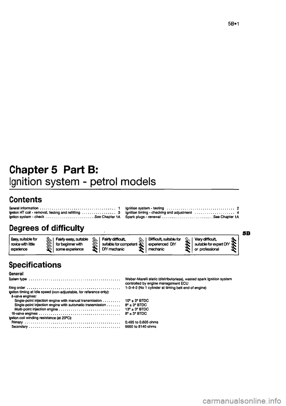
firing order Ignition timing at Idle speed (non-adjustable, for reference onlyy. 6-valve engines: Single-point injection engine with manual transmission .... Single-point injection engine with automatic transmission.. Multi-point injection engine 16-valve engines
Ignition
coil winding resistance (at 20°C): Primary Secondary
Weber-Marelli static (distributorless), wasted spark Ignition system controlled by engine management ECU
1
-3-4-2 (No 1 cylinder at timing belt end of engine)
10® ± 3° BTDC 6° ± 3° STDC 13° ±3° BTDC 8° x 3° BTDC
0.495 to 0.605 ohms 6660 to 8140 Ohms
Page 154 of 225
5B*2 Ignition system - petrol models
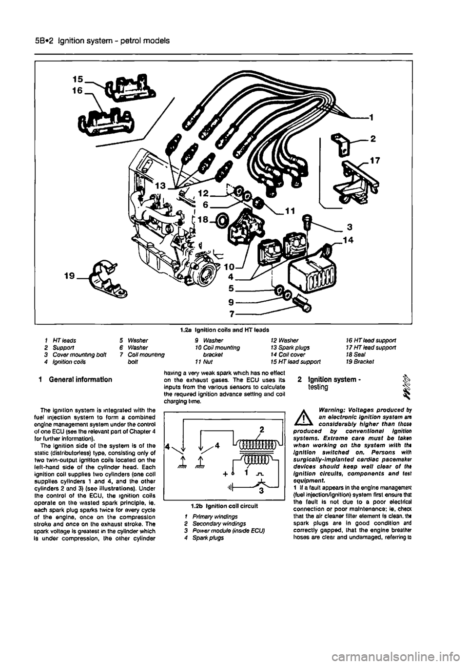
1 HT leads 2 Support 3 Cover mounting bdt 4 Ignition coifs
5 Washer 6 Washer 7 Coil mounting bolt
1.2s Ignition coils and HT leads 9 Washer 10 Coil mounting bracket
11
Nut
12 Waslrer 13 Spark plugs 14 Coll cover 15 HT lead support
16 HT lead support 17HTlead support 18 Seat Id Bracket
1 General information
The ignition system is integrated with the fuel injection system to form a combined engine management system under the control of one ECU (see the relevant part of Chapter 4 lor further Information). The Ignition side of the system is of the static (distributorless) type, consisting only of two twin-output Ignition coils located on the left-hand side of the cylinder head. Each ignition coil supplies two cylinders (one coll supplies cylinders 1 and 4, and the other cylinders 2 and 3) (see Illustrations). Under the control of the ECU, the ignition coils operate on the wasted spark principle, ie. each spark plug sparks twice for every cycle of the engine, once on the compression stroke and once on tho exhaust stroke. The spark voltage is greatest in the cylinder which Is under compression, the other cylinder
having a very weak spark which has no effect on the exhaust gases. The ECU uses Its Inputs from the various sensors to calculate the required ignition advance setting and coil chorging time.
1.2b Ignition coll circuit 1 Primary windings 2 Secondary windings 3 Power module
2 Ignition system -testing i
A
Warning: Voltages produced
by
an electronic Ignition system an considerably higher than (hose produced by conventional Ignition systems. Extreme care must be tak»n when working on tho system with thi Ignition switched on. Persons wilfl surgically-implanted cardiac pacemaker devices should keep well clear ot the ignition circuits, components and (oaf equipment 1 If a fault appears In the engine management (fuel injection/ignition) system first ensure that the fault is not due to a poor electrical connection or poor maintenance: ie, checK lhat the air cleaner filter element is clean, tht spark plugs are In good condition and correctly gapped, lhat the engine breather hoses are clear and undamaged, referring to
Page 156 of 225
501
Chapter 5 PartC:
Preheating system - diesel models
Contents
Glow plugs - removal, inspection and refitting 2 Preheating system - description and testing 1 Preheating system control unit - removal and refitting 3
Degrees of difficulty
Ea3y, suitable
for &
novice with little
|| experience ^
Fairty easy,
suitable for beginner with
some experience
jQ
Fairty diffctit, ^
suitable
for competent
DIY
mechanic
Difficult, suitable for
experienced DIY JR mechanic ^
Very difficult, ^ suitable fbrexpertDfY JR or professional ^
Specifications
Torque wrench setting Nm ibf ft Heater glow plugs 15 11
1 Preheating system -description and testing
Description 1 Each swirl chamber has a heater plug (commonly called a glow plug) screwed into it. The plugs are electrically-operated before and during start-up when the engine is cold. 2 Electrical feed to the glow plugs Is controlled by a relay/timer unit. The coolant temperature determines the period of heating that takes place. 3 A warning light in the instnjment panel tells the driver that preheating is taking place. When the light goes out, the engine is ready to be started. The voltags supply to the glow plugs continues for several seconds after the light goes out, If no attempt is made to start, the timer then cuts off the supply, In order to avoid draining the battery and overheating the glow plugs.
Testing 4 If the system malfunctions, testing is ultimately by substitution of known good units, but some preliminary checks may be made as follows. 5 Connect a voltmeter or 12-volt test lamp between the glow plug supply cable and earth (engine or vehicle metal). Make sure that the live connection is kept clear of the engine and bodywork. 6 Have an assistant switch on the ignition, and check that vottage is applied to the glow plugs. Note the time for which the warning light Is lit. and the total time for which voltage Is applied before the system cuts out. Switch off the ignition. 7 At an under-bonnet temperature of 20°C. typical times noted should be 5 or 6 seconds for warning light operation, followed by a further 10 seconds supply after the light goes out. Warning light time will increase with lower temperatures and decrease with higher temp-eratures.
8 If there Is no supply at all, the relay or associated winng is at fault. 9 To locate a defective glow plug, disconnect the main supply cable and the interconnecting strap from the top of the glow plugs. Be careful not to drop the nuts and washers. 10 Use a continuity tester, or a 12-voH test lamp connected to the battery positive terminal, to check for continuity between each glow plug terminal and earth. The resistance of a glow plug in good condition is very low (less than 1 ohm), so if the test lamp does not light or the continuity tester shows a high resistance, the glow plug is certainly defective. 11 If an ammeter is available, the current draw of each glow plug can be checked. After an initial surge of 15 to 20 amps, each plug should draw approximately 12 amps. Any plug which draws much more or less than this is probably defective. 12 As a final check, the glow plugs can be removed and Inspected as described in the following Section.
Page 157 of 225
5C«2 Preheating system - diesel models
2.3 No 4 glow plug showing the main supply lead end the interconnecting strap 2.5 Removing a glow plug
2 Glow plugs -removal, Inspection and refitting
Removal Caution: If the preheating system has just been energised, or If tho engine has been running, the glow plugs will be very hot
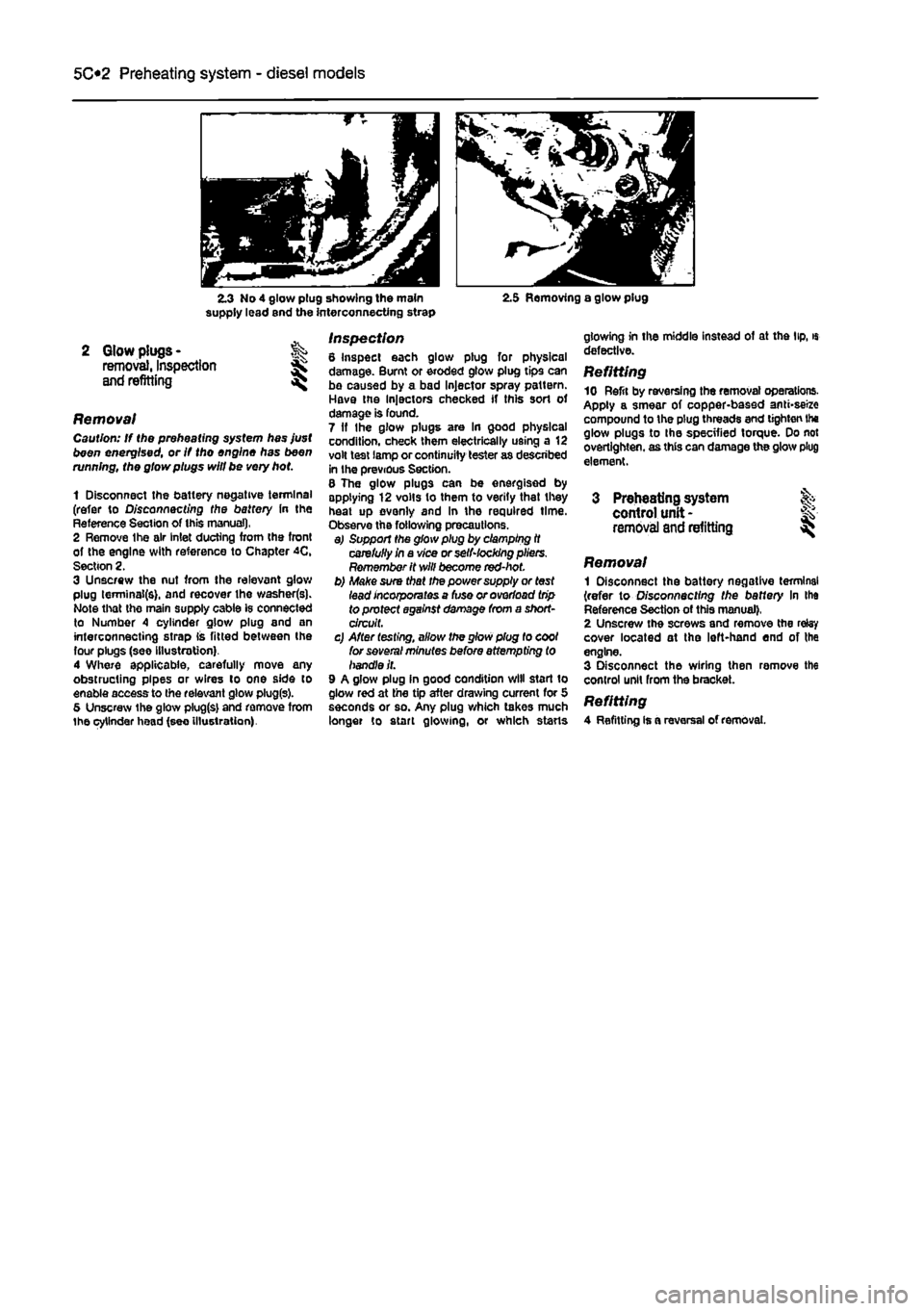
1 Disconnect the battery negative terminal (refer to Disconnecting the battery in the Reference Section of this manual), 2 Remove Ihe air Inlet ducting from the front of the engine with reference to Chapter 4C, Section 2. 3 Unscrew the nut from the relevant glow plug lerminai(s). and recover the washer(s). Note that tho main supply cable is connected to Number 4 cylinder glow plug and an interconnecting strap lis fitted between the four plugs (see Illustration). 4 Where applicable, carefully move any obstructing pipes or wires lo one side to enable access to the relevant glow plug(s). 5 Unscrew the glow plug(s) and remove from the cylinder head (see illustration).
Inspection 8 Inspect each glow plug for physical damage. Burnt or eroded glow plug tips can bo caused by a bad Injector spray pattern. Have the Injectors checked if this sort of damage is found. 7 If Ihe glow plugs are In good physical condition, check them electrically using a 12 volt test lamp or continuity tester as described in the previous Section. 8 The glow plugs can be energised by applying 12 volts to them to verity that they heat up evenly and In the required time. Observe the following precautions. a) Support the glow plug by clamping it carefully in a vice or selNocking pliers. Remember it will become red-hot. b) Make sura that the power supply or test lead incorporates a fuse or overload trip to protect against damage from a short-circuit. c) After testing, allow the glow plug to cool for several minutes before attempting to handle it. 9 A glow plug In good condition will start to glow red at the tip after drawing current for 5 seconds or so. Any plug which takes much longer to start glowing, or which starts
glowing in the middle instead of at the lip, « defective. Refitting 10 Refit by reversing the removal operations. Apply a smear of copper-based anti-seize compound to the plug threads and tighten Ihe glow plugs to Ihe specified torque. Do not overtighten, as this can damage the glow plug element.
3 Preheating system control unit -removal
and
refitting I
Removal 1 Disconnect the battery negative terminal (refer to Disconnecting the baffery In Ihe Reference Section of this manual). 2 Unscrew the screws and remove the relay cover located at the left-hand end of the engine. 3 Disconnect the wiring then remove the control unit from the bracket. Refitting 4 Refitting is a reversal of removal.
Page 163 of 225
7A*2 Manual transmission
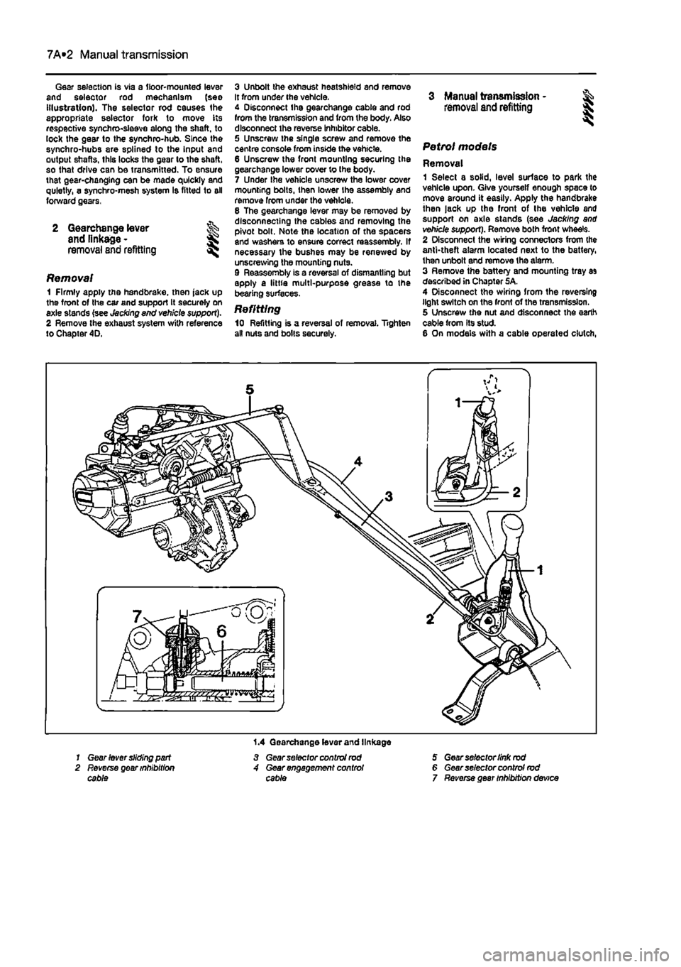
Gear selection is via a floor-mounted lever and selector rod mechanism (seo Illustration). The selector rod causes the appropriate selector fork to move its respective synchro-sleeve along the shaft, to lock the gear to the synchro-hub. Since the synchro-hubs are splined to the Input and output shafts, this locks the gear to the shaft, so that drive can be transmitted. To ensure that gear-changing can be made quickly and quietly, a synchro-mesh system Is fitted to all forward gears,
2 Gearchange lever and linkage -
removal and refitting ^
Removal 1 Firmly apply the handbrake, then jack up the front of the car and support It securely on axle stands {see Jacking and veh/cte support). 2 Remove the exhaust system with reference to Chapter 4D.
3 Unbolt the exhaust heatshield and remove It from under the vehicle. 4 Disconnect the gearchange cable and rod from the transmission and from the body. Also disconnect the reverse inhibitor cable. 5 Unscrew the single screw and remove the centre console from inside the vehicle. 6 Unscrew the front mounting securing the gearchange lower cover to the body. 7 Under Ihe vehicle unscrew the lower cover mounting bolts, then lower Ihe assembly and remove from under the vehlole. 8 The gearchange lever may be removed by disconnecting the cables and removing the pivot bolt. Note the location of the spacers and washers to ensure correct reassembly. If necessary the bushes may be renewed by unscrewing the mounting nuts. 9 Reassembly is a reversal of dismantling but apply a little multi-purpose grease to the bearing surfaces.
Refitting 10 Refitting is a reversal of removal. Tighten all nuts and bolts securely.
3 Manual transmission - & removal and refitting § S
Petrol models
Removal 1 Select a solid, level surlace to park the vehicle upon. Give yourself enough space to move around it easily. Apply the handbrake then jack up the front of the vehicle and support on axle stands (see Jacking and vehicle support). Remove both front wheels. 2 Disconnect the wiring connectors from (he anti-theft alarm located next to the battery, then unbolt and remove the alarm. 3 Remove the battery and mounting tray as described in Chapter 5A. 4 Disconnect the wiring from the reversing light switch on the front of the transmission. 5 Unscrew the nut and disconnect the earth cable from its stud. 6 On models with a cable operated clutch,
1.4 Gearchange lever and linkage 1 Gear lever sliding part 3 Gear selector control rod 5 Gear selector link rod 2 Reverse gear inhibition 4 Gear engagement control 6 Gear selector control rod cable cable 7 Reverse gear inhibition device
Page 168 of 225
Automatic transmission 7B*3
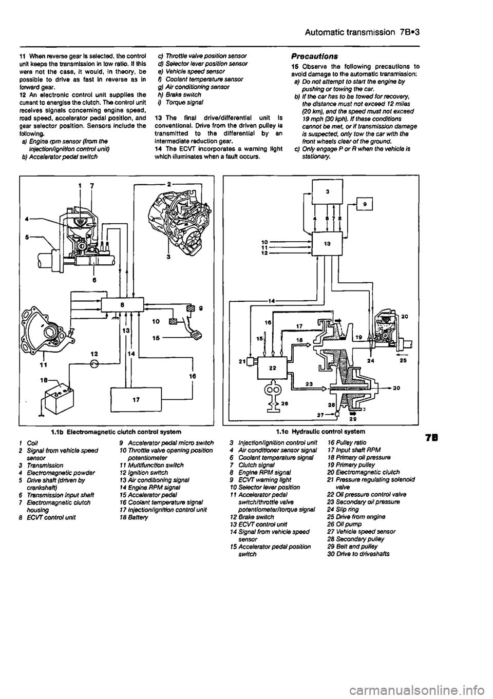
11 When reverse gear Is selected, the control unit keeps the transmission In tow ratio, if this were not the case, it would, In theory, be possible to drive as fast In reverse as in forward gear. 12 An electronic control unit supplies the current to energise the clutch. The control unit receives signals concerning engine speed, road speed, accelerator pedal position, and gear selector position, Sensors include the following. a) Engine rpm sensor (from the Injection/ignition control unit) b) Accelerator pedal switch
c) Throttle valve position sensor d) Selector lever position sensor e) Vehicle speed sensor f) Coolant temperature sensor g) Air conditioning sensor h) Brake switch I) Torque signal
13 The final drive/differential unit Is conventional. Drive from the driven pulley is transmitted to the differential by an Intermediate reduction gear. 14 The ECVT incorporates a warning light which illuminates when a fault occurs.
Precautions 1$ Observe the following precautions to avoid damage to the automatic transmission: a) Do not attempt to start the engine by pushing or towing the car. b) If the car has to be towed for recovery, the distance must not exceed 12 miles (20
km),
and the speed must not exceed
19
mph
(30 kph).
If these conditions cannot be met, or If transmission damage is suspected, only tow the car with the front wheels clear of the ground. c) Only engage P or R when the vehicle is stationary.
1.1b Electromagnetic f Coil 2 Signal from vehicle speed sensor 3 Transmission 4 Electromagnetic powder 5 Drive shaft (driven by crankshaft) $ Transmission input shaft 7 Electromagnetic clutch housing 8 ECVT control unit
clutch control system 9 Accelerator pedal micro switch 10 Throttle
vafve
opening position potentiometer 11 Multifunction switch 12 Ignition switch
13
Air conditioning
signal
14 Engine PPM
signal
15 Accelerator pedal 16 Coolant temperature signal 17 Injection/ignition control unit 18 8attery
1.1c Hydraulic control system 3 Injection/ignition control unit 4 Air conditioner sensor
signal
6 Coolant temperature signal 7 Clutch signal 8 Engine RPM
signal
9 ECVT warning light 10 Selector lever position 11 Accelerator
pedal
switch/throttle
valve
potentiometer/torque signal 12 Brake switch 13
ECVT
control unit 14 Signal from vehicle speed sensor
15
Accelerator pedal position switch
16 Pulley ratio 17 Input shaft RPM 18 Primary oil pressure
19
Primary pulley 20 Electromagnetic clutch 21 Pressure regulating solenoid valve 22 Oil pressure control valve 23 Secondary oil pressure 24 Slip ring 25 Drive from engine 26 Oil pump 27 Vehicle speed sensor 28 Secondary pulley 29 Belt and pulley 30 Drive to drlveshafts
Page 178 of 225
9*2 Braking system
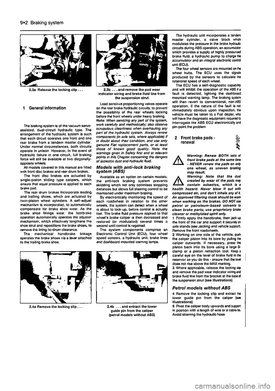
2.3a Release tho locking clip ...
1 General information
The braking system is of the vacuum servo-assisted. dual-circuit hydraulic type. The arrangement of Ihe hydraulic system is such that each circuit operates one front ond ono rear brake from a tandem master cylinder. Under normal circumstances, both circuits operate In unison However, in the event of hydraulic failure in one circuit, lull braking force will still be available at two diagonally-opposite wheels. All models covered in this manual are fitted with front disc brakes and rear drum brakes. The front disc brakes are aotuated by single-piston sliding lype calipers, which ensure lhat equal pressure is applied to each brake pad. The rear drum brakes incorporate leading and trailing shoes, which are actuated by twin-piston wheel cylinders. A self-adjust mechanism is incorporated, to automatically compensate for brako shoe wear. As the brake shoe linings wear, the footbrnke operation automatically operates the adjuster mechanism, which effectively lengthens the shoe strut and repositions the brake shoes, to remove the llning-to-drum clearance. The mechanical handbrake linkage operates the brake shoos via a lever attached to the trailing brake shoe.
2.3b ... and remove the pad wear indicator wiring and brake fluid line from the suspension strut Load sensitive proportioning valves operate on the rear brake hydraulic circuits, to prevent the possibility of the rear wheels locking before the front wheels under heavy braking. Note: When servicing any part of the system, work carefully and methodically; also observe scmpulous cleanliness when overhauling any part of the hydraulic sysiem. Always renew components (in axle sets, where applicable) if In doubt about their condition, and use only genuine Fiat replacement parts, or at least those of known good quality. Note the warnings given in Safety first and at relevant points in this Chapter concerning fhe dangers of asoestos dust and hydraulic fluid.
Models with anti-lock braking system (ABS) Available as an option on certain models, the anti-lock braking system prevents skidding which not only optimises stopping distances but allows full steering control to be maintained under maximum braking. By electronically monitoring the speed of each roadwheel in relation to the other wneete, Ihe system can detect when a wheel is about to lock-up, before control is actually lost. The brake fluid pressure applied to that wheel's brake caliper is then decreased and restored (or modulated) several times a second until control
£s
regained. The system components comprise an Electronic Control Unit (ECU), four wheel speed sensors, a hydraulic unit, brake lines and dashboard mounted warning lamps.
The hydraulic unit incorporates a tandem master cylinder, a valve block which modulates the pressure in the brake hydrauli: circuits during ABS operation, an accumulator which provides a supply of highly pressursed brake fluid, a hydraulic pump to charge Ihe accumulator and an integral electronic control unit (ECU). The four wheel sensors are mounted on the wheel hubs. The ECU uses the signals produced by the sensors to calculate Ihe rotational speed of each wheel, The ECU has a self-diagnostic capability and will inhibit the operation of the ABS il a fault is detected, lighting the dashboard mounted warning lamp. The braking system will then revert lo conventional. non-ABS operation. II the nature of the laull ie not immediately obvious upon inspection, the vehicle must be taken to a Fiat dealer, who will have the diagnostic equipment
required
lo interrogate the ABS ECU electronically and pin-point the problem
2 Front brake pads - & renewal S
A
Warning: Renew BOTH sets ol front brake pads at the same
time
- NEVER renew the pads on
only
one wheel, as uneven braking may result
A
Warning: Note that the dust created by wear of the pads
may
contain asbestos, which is a health hazard. Never blow It out with compressed air, and don't inhale any of
it.
An approved filtering mask should be worn when working on the brakes. DO NOT use petrol or petroleum-based solvents to clean brake parts; use proprietary braks cleaner or methylated spirit only. 1 Firmly apply the handbrake, then jack up the front of the car and support it securely
on
axle stands (see Jacking and vehicle supporti. Remove the front roadwheeis. 2 Wording on one side of the vehicle, puth the caliper piston into its bore by pulling the caliper outwards. If necessary, press the piston back into its bore using a large G-clamp or a piston retraction tool. Keep a careful eye on the level of brake llufd in Ihe I reservoir as you do this - ensure that the
level
I does not rise above the MAX marking. 3 Whore applicable, release the locking dp and remove the pad wear indicator
wiring end
brake fluid line from the bracket at Ihe
base of
the suspension strut (see illustrations).
Petrol models without ABS 4 Remove the locking clip and exlracl the lower guide pin from the caliper (see illustrations) 5 Pivot the caliper body upwards and support In position with a length of wire or a cabie-fc. Avoid straining the hydraulic hose.
2,4a Remove the locking clip ... 2.4b ... and extract the lower guide pin from the caliper (petrol models without ABS)
Page 190 of 225
Suspension and steering 10*2
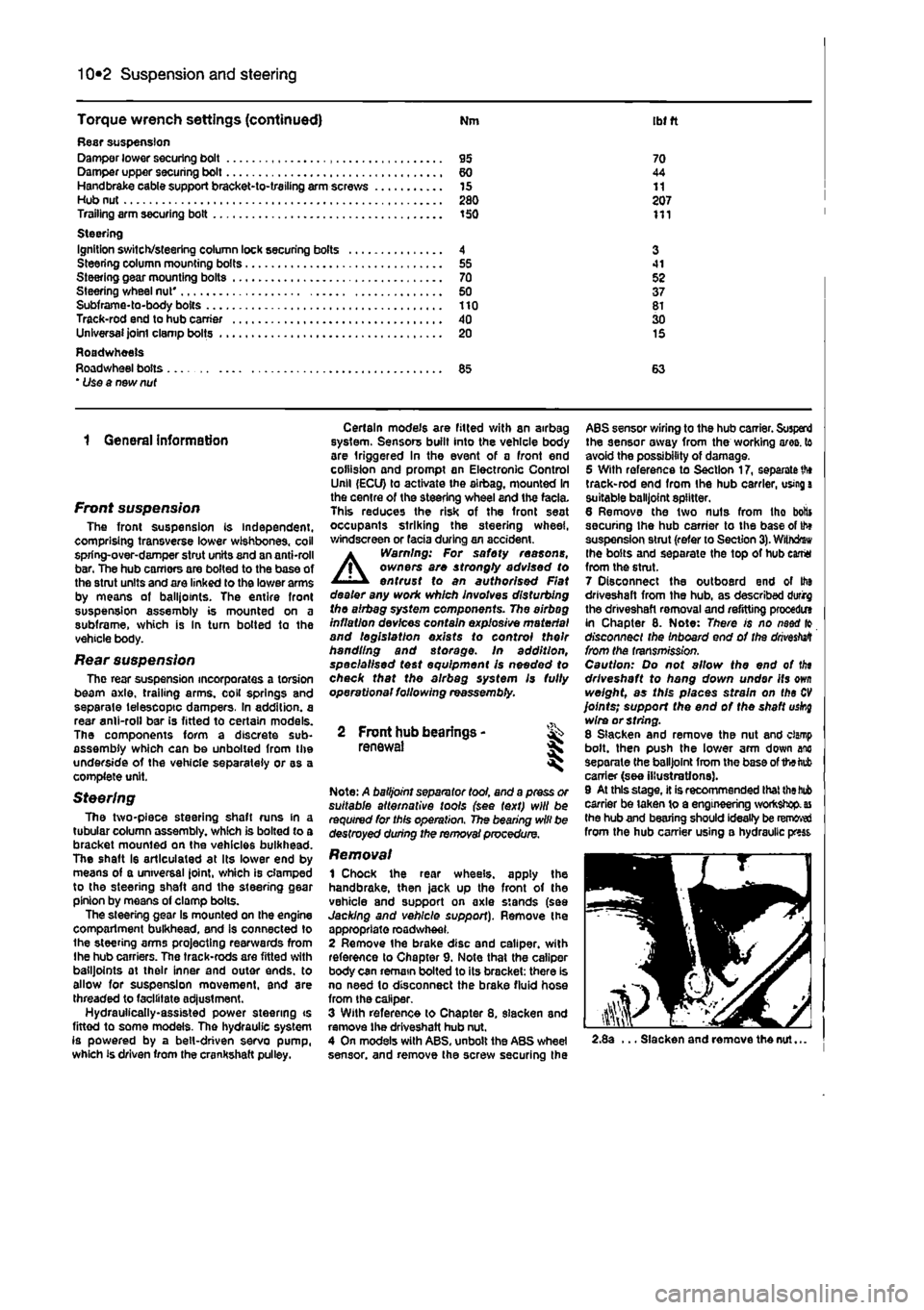
Torque wrench settings (continued) Nm ibt ft Rasr suspension Damper lower securing bolt 95 70 Damper upper securing bolt 60 44 Handbrake cable support bracket-to-trailing arm screws 15 11 Hub nut 280 207 Trailing arm securing bolt 150 111 Steering Ignition switch/steering column lock securing bolts 4 3 Steering column mounting bolts 55 41 Steering gear mounting bolts 70 52 Steering wheel nut' 50 37 Subframe-to-body bolts 110 81 Track-rod end to hub carrier 40 30 Unlversaijointclampbolts 20 15 Roadwheels Roadwheel bolts 85 63 * Use a new nut
1 General information
Front suspension The front suspension is independent, comprising transverse lower wishbones, coil spring-over-damper strut units and an anti-roll bar. The hub carriors are bolted to the base of the stmt units and are linked to the lower arms by means ot balliotnts. The entire front suspension assembly is mounted on a subframe, which is In turn botted to the vehicle body.
Rear suspension The rear suspension incorporates a torsion beam axle, trailing arms, coil springs and separate telescopic dampers. In addition, a rear anil-roll bar is fitted to certain models. The components form a discrete sub-assembly which can be unboiled from the underside of the vehicle separately or as a complete unit.
Steering The two-piece steering shaft runs in a tubular column assembly, which is bolted to a bracket mounted on the vehicles bulkhead. The shaft Is articulated at its lower end by means of a universal Joint, which is clamped to the steering shaft and the steering gear pinion by moans of clamp bolts. The steering gear is mounted on the engine compartment bulkhead, and is connected to the steering arms projecting rearwards from Ihe hub carriers. The track-rods are fitted with balljoints at their inner and outer ends, to allow for suspension movement, and are threaded to facilitate ad|ustment. Hydrauiically-assisted power steering ts fittod to some models. The hydraulic system is powered by a belt-driven servo pump, which is driven from the crankshaft pulley.
Certain models are fitted with an airbag system. Sensors built into the vehicle body are triggered in the event of a front end collision and prompt an Electronic Control Unll (ECU) to activate the airbag, mounted In the centre of the steering wheel and the facia. This reduces the risk of the front seat occupants striking the steering wheel, windscreen or facia during an accident.
A
Warning: For safety reasons, owners are strongty advised to entrust to an authorised Flat dealer any work which involves disturbing the airbag system components. The airbag inflation devices contain explosive material and legislation exists to control their handling and storage, in addition, specialised test equipment Is needed to check that the airbag system Is fully operational following reassembly.
2 Front hub bearings -renewal *
Note: A balljoint separator tool, and a press or suitable alternative tools (see text) will be required for this operation. The bearing will be destroyed during the removal procedure.
Removal 1 Chock the rear wheels, apply the handbrake, then jack up the front of the vehicle and support on axle stands (see Jacking and vehicle support). Remove the appropriate roadwheel. 2 Remove the brake disc and caliper, with reference to Chapter 9. Note that the caliper body can remain bolted to its bracket: there is no need lo disconnect the brake fluid hose from the caliper. 3 With reference to Chapter 8. slacken and remove the driveshaft hub nut. 4 On models with ABS, unbolt the ABS wheel sensor, and remove the screw securing the
ABS sensor wiring to the hub carrier. Suspend the sensor away from the working ares, to avoid the possibility of damage. 5 With reference to Section 17, separate
th»
track-rod end from the hub carrier, using
a
suitable balljoint splitter. 6 Remove the two nuts from tho botts securing Ihe hub carrier to the base of th» suspension strut (refer to Section
3).
Withdrew the bolts and separate the top of hub earrtt from the strut. 7 Disconnect the outboard end of Ito driveshaft from the hub, as described durirg the driveshaft removal and refitting procedm in Chapter 8. Note: There is no naod fo disconnect the Inboard end of the
drivestett
from the transmission. Caution: Do not allow the end of tin driveshaft to hang down under its
own
weight, as this places strain on the
CV
joints; support the end of the shaft uskg wire or string. 8 Slacken and remove the nut and clamp bolt, then push the lower arm down anc separate the balljoint from the base of the tab carrier (see illustrations). 9 At this stage, it is recommended that
the bub
carrier be taken to a engineering workshop,
as
the hub and bearing should ideally be removed from the hub carrier using a hydraulic press
2.8a ... Slacken and remove the nut...