engine coolant FIAT PUNTO 1994 176 / 1.G Repair Manual
[x] Cancel search | Manufacturer: FIAT, Model Year: 1994, Model line: PUNTO, Model: FIAT PUNTO 1994 176 / 1.GPages: 225, PDF Size: 18.54 MB
Page 133 of 225
4A*2 Fuel system -
single-point
petrol Injection models
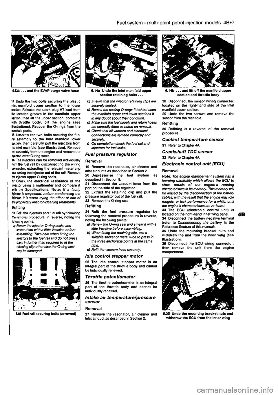
6.13b ... and tho EVAP purge valve hose
14 Undo the two bolls securing the plastic nlet manifold upper section to the lower section. Release the spark plug HT lead from Ihe location groove in the manifold upper section, then lift the upper section, complete with throttle body, off the engine (see illustrations). Recover the O-nngs from the manifold ports. 16 Unscrew the two bolts securing the fuel rail assembly to the Inlet manifold lower section, inen carefully pull the injectors from ttie inlet manifold (see Illustration). Remove
tt>e
assembly from the engine and remove the injector lower O-ring seals. t& The injectors can be removed individually from the fuel rail by disconnecting the wiring connector, extracting the relevant metal clip
ano
easing the injector out of the rail. Remove themjector upper O-ring seals. 17 Check the electrical resistance of the tractor using a multimeter and compare it with the Specifications. Note: If a faulty Rector fc suspected, before condemning Wie
Rector,
it is worth trying the effect of one of m
proprietary
injector-cleaning treatments. Refitting
15 Refit the injectors and fuel rail by following tie removal procedure, In reverse, noting the Mowing points:
4} Re/few
the Injector O-ring seals, and
smear
them with a little Vaseline before assembling. Take care when fitting the
injectors
to the fuel rail and do not press
them
in further than required to fit the
retaining
clip otherwise the O-ring
seal may
be damaged.
6.14a Undo the inlet manifold upper section retaining bolts ... b) Ensure that the injector retaining clips are securely seated. c) Renew the sealing O-nngs fitted between the manifold upper and lower sections if in any doubt about their condition. d) Make sure the fuel supply and return hoses are correctly fitted as noted on removal. e) Check that all vacuum and electrical connections are remade correctly and securely. f) On completion check the fuel rail and injectors tor fuel leaks.
Fuel pressure regulator
Removal 19 Remove the resonator, air cleaner and inlet air ducts as described In Section 2. 20 Depressurise the fuel system as described In Section 9. 21 Disconnect the vacuum hose from the port on the side of the regulator. 22 Extract the retaining clip and pull the pressure regulator out of the fuel rail. 23 Remove the O-ring seal. Refitting 24 Refit the fuel pressure regulator by following the removal procedure in reverse, noting the following points: a) Renew the O-ring
seaJ
and smear it with a little Vaseline before assembling. b) When fitting the retaining clip, use a suitable socket or metal tube to press in the three anchorage points at the same time. c) Refit the vacuum hose securely.
Idle control stepper motor 25 The idle control stepper motor is an Integral part of the throttle body and cannot be individually renewed.
Throttle potentiometer 26 The throttle potentiometer Is an integral part of the throttle body and cannot be individually renewed.
Intake air temperature/pressure sensor
Removal
6.14b ... and lift off the manifold upper section and throttle body 28 Disconnect the sensor wiring connector, located on the right-hand side of the Inlet manifold upper section. 29 Undo the two screws and remove the sensor from the manifold. Refitting 30 Refitting is a reversal of the removal procedure. Coolant temperature sensor 31 Refer to Chapter 4A.
Crankshaft TDC sensor 32 Refer to Chapter 4A.
Electronic control unit (ECU)
Removal Note: 77?e engine management system has a learning capability which allows the ECU to store details of the engine's running characteristics in Its memory. This memory will be erased by the disconnection of the battery cables, with the result that the engine may idle roughly, or lack performance for a while, until the engine's characteristics are re-learnt. 33 The ECU (electronic control unit) is located on the right-hand inner wing panel. 34 Disconnect the battery negative terminal (refer to Disconnecting the battery In the Reference Section of this manual). 35 Undo the mounting bracket nuts and withdraw the unit from the inner wing (see Illustration). 36 Disconnect the ECU wiring connector, then remove the unit from the engine compartment.
6.15 Fuel rail securing bolts (arrowed) 27 Remove the resonator, air cleaner and inlet air duct as described in Section 2. 6.35 Undo the mounting bracket nuts and withdraw the ECU from the inner wing
Page 134 of 225
4A*2 Fuel system -
single-point
petrol Injection models
Refitting 37 Refitting Is a reversal of removal making sure that the wiring connector is securely reconnected.
Inertia safety switch 36 Refer to Chapter 4A, Fuel injection system relays Removal 39 The fuel injection system twin relay Is located under a plastic cover on the engine compartment bulkhead. 40 The main purpose of the relay Is to supply current to the fuel pump, ignition coils, oxygen sensor, Injectors and EVAP solenoid. The relay is controlled by the ignition switch. A15 amp fuse, protecting ihe fuel pump, oxygen sensor and EVAP solenoid is located adjacent to the relay. 41 Remove the cover and pull the relay directfy from Its socket. Refitting 42 Refitting is a reversal of removal.
7 Fuel pump and fuel gauge sender unit - JK removal
and
refitting ^
Removal Note: Refer fo (he warning given in Section 1 before proceeding. 1 Disconnect the battery negative terminal (refer to Disconnecting the battery In the Reference Section of this manual). 2 Depreasurise the fuel system as described in Section 9. 3 Remove the rear soat as described In Chapter 11. Prise the fuel pump access cover out of the floor panel to gain access to the pump unit. On later models, undo the three retaining screws to release the cover. 4 Disconnect the wiring connector. 5 Bearing In mind the warning given In Section t, disconnect Ihe fuel supply and, where applicable, the return lines from tho pump unit by pressing the tabs. Plug the ends of the lines or cover them with adhesive tape. 6 Using a suitable tool, unscrew the large ring nut and carefully withdraw the fuel pump/fuel tank sender unit assembly from the fuel tank, along with its sealing rtng. 7 If necessary, the unit can be dismantled and the pump and sender unit separated. If this is (he case, carefully note the correct fitted positions of all components while dismantling the unit, and use these notes on reassembly to ensure that all items are correctly fitted.
Refitting 8 Refitting is a reversal of the removal procedure using a new sealing ring. Prior to refitting the access cover, reconnect the battery, then start the engine and check the fuel line unlon(s) (or signs of i
Fuel
tank -removal and refitting
Refer to Chapter 4A.
9 Fuel injection system -depressurisatton
Note: Refer to the warning given In Section 1 before proceeding.
A
Warning: The following procedure will merely relieve the pressure In the fuel system • remember that fuel will still be present In the system components and take precautions accord-ingly before disconnecting any of them. 1 The fuel system referred to in this Section is defined as the lank-mounted fuel pump, tha fuel filter, the fuel rail, the fuel injectors, and the metal pipes and flexible hoses of the fuel lines between these components. All these contain fuel which will be under pressure while the engine Is running and/or while the Ignition is switched on. The pressure will remain for some time after the Ignition has been switched off. and must be relieved before any of these components are disturbed for servicing work. 2 Disconnect the battery negative terminal (refer to Disconnecting the battery In the Reference Section of this manual). 3 Have a large rag ready to cover the union to be disconnected and, if possible, place a con-tainer beneath the relevant connection/union. 4 Slowly loosen the connection or union nut (as applicable) to avoid a sudden release of pressure, and ensure that the rag is wrapped around the connection to catch any fuef spray which may be expelled. Once the pressure is released, disconnect the fuel line, and Insert plugs to minimise fuel loss and prevent the entry of dirt Into the fuel system. Note that on later models, quick-release fuel couplings are used on many of the fuel line connections. To release these couplings, depress the two clips on the side of the coupling while keeping the fuel line pushed In. With the clips depressed, slowly withdraw the fuel line from the coupling allowing the fuel pressure to release, then withdraw the fuel line fully.
10 Inlet manifold-removal
and
refitting
Note: Refer fo the warning given in Section 1 before proceeding.
1242 cc (8-valve) engines
Removal 1 Remove ihe throttle body assembly as described in Section 5.
2 Remove the fuel rail and injectors at described in Section 5. 3 Drain the cooling system ss described n Chapter 1A. 4 Disconnect the wiring connector from ih* coolant temperature sensor (situated on it* left-hand side of the manifold). 5 Undo the bolt securing the accelerator cable mounting bracket to the manifold, am position it clear of the manifold. 6 Slacken the retaining clip and disconnect the coolant hose from the rear of the mandold 7 Disconnect the brake vacuum hose, 6 Undo the seven manifold retaining nuisw bolts, and remove the manifold from tta engine. Remove the gasket and discard tti new one should be used on refitting. Refitting
9 Refitting is a reverse of the removjf procedure, noting the following points: a) Ensure that the manifold and cylinder lim mating surfaces are dean and
dry.
and fill new manifold gasket. Refit the
manifold
and securely tighten Its retaining
nuts.
b) Ensure all relevant hoses are recorwscfed fo their original positions and are
sacurtfy
held (Where necessary; by the
retaining
clips. c) Refit the fuel rail and injectors, and
the
throttle body assembly with
reference to
Sect/on 5. d) On completion, refill the cooling
system
as described in Chapter 1A. 1242 cc (16-valve) engines
Removal 10 Disconnect the battery negative ternnncf (refer to Disconnecting the battery in ths Reference Section of this manual). 11 Remove the resonator, air cleaner and inlet air duct as described In Section 2. 12 Drain the cooling system as described r, Chapter 1A. 13 Free the accelerator inner cable from IN throttle cam. remove the outer cable spring dip. then pull the outer cable out from itt mounting bracket rubber grommet. 14 From the side of the throttle boOf, disconnect the wiring connectors from the throttle potentiometer and the Idle contrd stepper motor. Disconnect the coolant temperature sensor wiring connector located in the Inlet manilold below the throttie bodr, and disconnect the brake servo vacuum hose. 15 Disconnect Ihe wiring connectors for the fuel in|ector harness and the Intake a* temperature/pressure sensor, thtn disconnect the fuel pressure regulator vacuum hose and the EVAP purge valve
hose
(see illustration). 16 Undo Ihe two bolts securing the plastic Inlet manifold upper section to the lower section. Release the spark plug HT lead from the location groove in the manifold upper section, then lift Ihe upper section, complete with throttle body, off the engine. Recover
the
O-rings from the manifold pons.
Page 137 of 225
Fuel system - diesel models 4C*3
Torque wrench settings Nm Ibfft Fuel injection pump roar bracket .. . 29 21 Fuel Injection pump .... 25 18 Fuel Injectors 41 Fuel pipe union nuts .... 30 22 Inlet manifold .... 24 18 Lower oil tiller mounting and injection pump mounting nut ..... .... 71 S2 Turbocnarger to exhaust manifold .... <10 30 Upper Dtl filter mounting end injection pump mounting nut 98 72
1 General information and precautions
General information The fuel system consists of a rear-mounted fust tank, a fuel filter with integral water separator, a fuel injection pump, in|eciors and associated components. A turbocharger is fitted to TDS, TD and TDSX models. Fuel Is drawn from the fuel tank to the fuel Injection pump by a vane-type transfer pump Incorporated in the fuel injection pump. Before reaching tho pump, the fuel passes through a fuel filter, where foreign matter and water aro removed. Excess fuel lubricates the moving components of the pump, and Is then returned to the tank. On turbo models with the Bosch fuel Injection systom, an eiectncally operated heater is incorporated In the fuel filter housing. The fuel injection pump is driven at half-crankshaft speed by the timing belt. The nigh pressure required to inject tho fuel into the compressed air in the swirl chambers Is achlovod by a cam plate acting on a single piston on the Bosch pumo, or by two opposed pistons forced together by rollers running in a cam ring on the Lucas (CAV) pump. Tlie fuel passes through acentral rotor with a single outlet drilling which aligns With ports leading to the Injector pipes. Fuel metering is controlled by a centrifugal governor, which reacts to accelerator pedal
position end engine speed. The governor is linked lo a metering valve, which increases or decreases the amount of fuel delivered at each pumping stroke. On turbocharged models, a separate device also Increases luel delivery with increasing boost pressure. Basic injection timing is determined when the pump is fitted. When the engine is running, it Is varied automatically to suit the prevailing engine speed by a mechanism which turns the cam plate or ring, Tho four fuel injectors proouco a homogeneous spray of fuel Into the swirl chambers located In the cylinder head. The Injectors are calibrated to open end close at critical pressures lo provide efficient and even combustion. Each injector needle is lubricated by fuel, which accumulates In the spring chamber and is channelled to the injection pump return hose by loak-off pipes Bosch or Lucas fuel system components mBy be fitted, depending on the model. Components from the latter manufacturer are marked either CAV. Roto-dlesel or Con-diesel. depending on their date and place of manufacture. With the exception of the fuel filter assembly, replacement components must be of tho same make as those originally fitted. Cold starting is assisted by preheater or glow plugs fitted to each swirl chamber. On the Bosch injection pump, an automatic cold Injection advance device operated through a thermal switch, advances the injection timing by Increasing the fuel pressure. The device operates at coolant temperatures below 55° C,
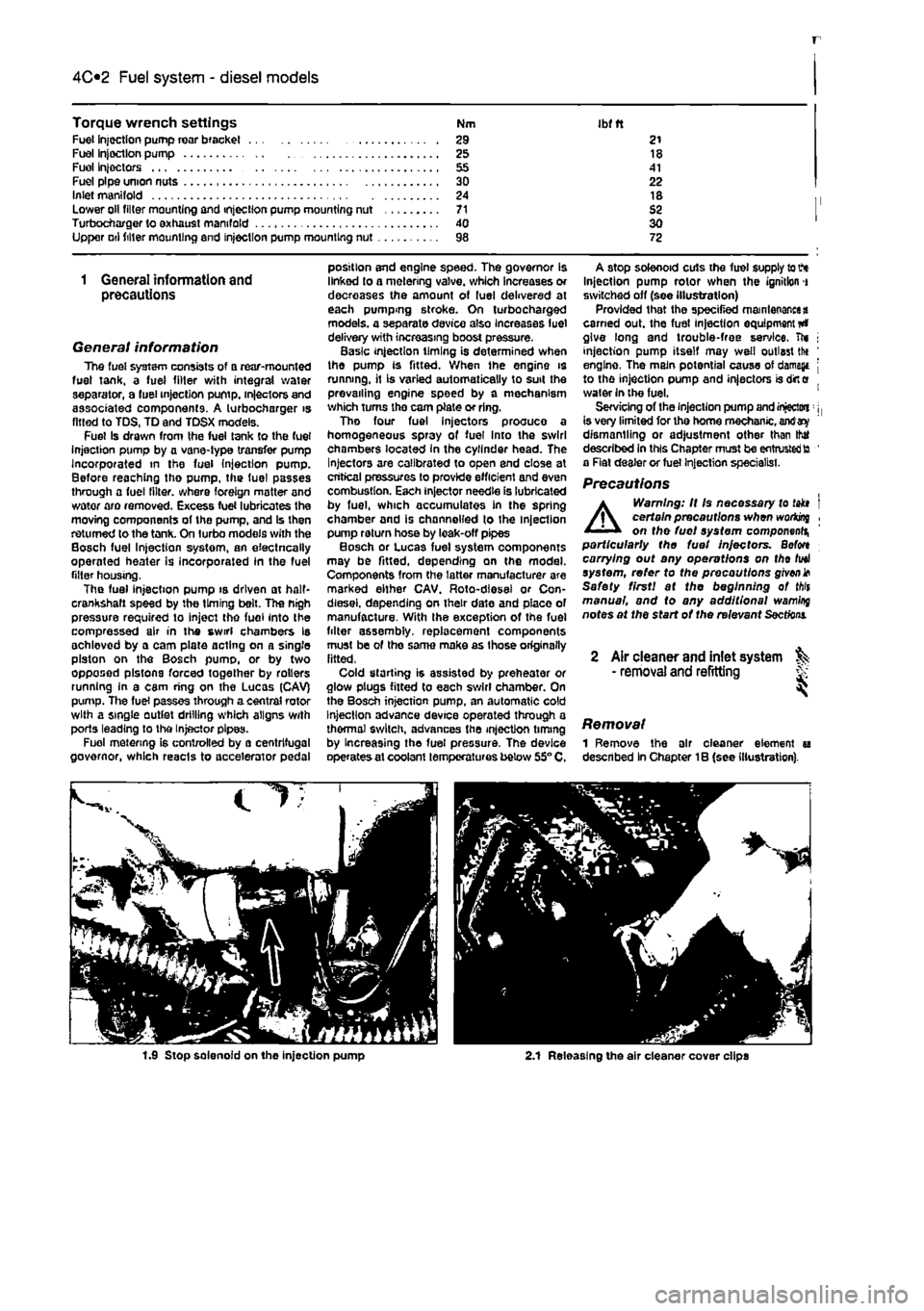
A stop solenoid cuts the fuel supply to V* Injection pump rotor when the ignition i switched off (see illustration) Provided that the specified maintenance* earned out. the fuel injection equipment #» give long and trouble-free service, ft* j injection pump itself may well outlast tlx ' engine, The main potential cause of damage j to the injection pump and injectors is dirt e water in the fuel. 1 Servicing of the injection pump and injectwi: j, is very limited for tho home mechanic, antf dismantling or adjustment other than thtf described In this Chapter must be entrusted to ' a Rat dealer or fuel Injection specialist.
Precautions
A
Warning: It Is necessary to takt I certain precautions when woriong , on the fuel system component^ particularly the fuel Injectors. Befon carrying out any operations on tho fuel system, refer to the precautions given* Safety first! at the beginning of Mis manual, and to any additional wamlrq notes at the start of the relevant
Sections.
2 Air cleaner and inlet system ^ • removal and refitting S
Removal 1 Remove the air cleaner element u described In Chapter 1B (see illustration).
1.9 Stop solenoid on the injection pump 2.1 Releasing the air cleaner cover clips
Page 151 of 225
5A«2 Starting and charging systems
5.9a Unbolting the alternator upper bracket from the rear of the coolant pump
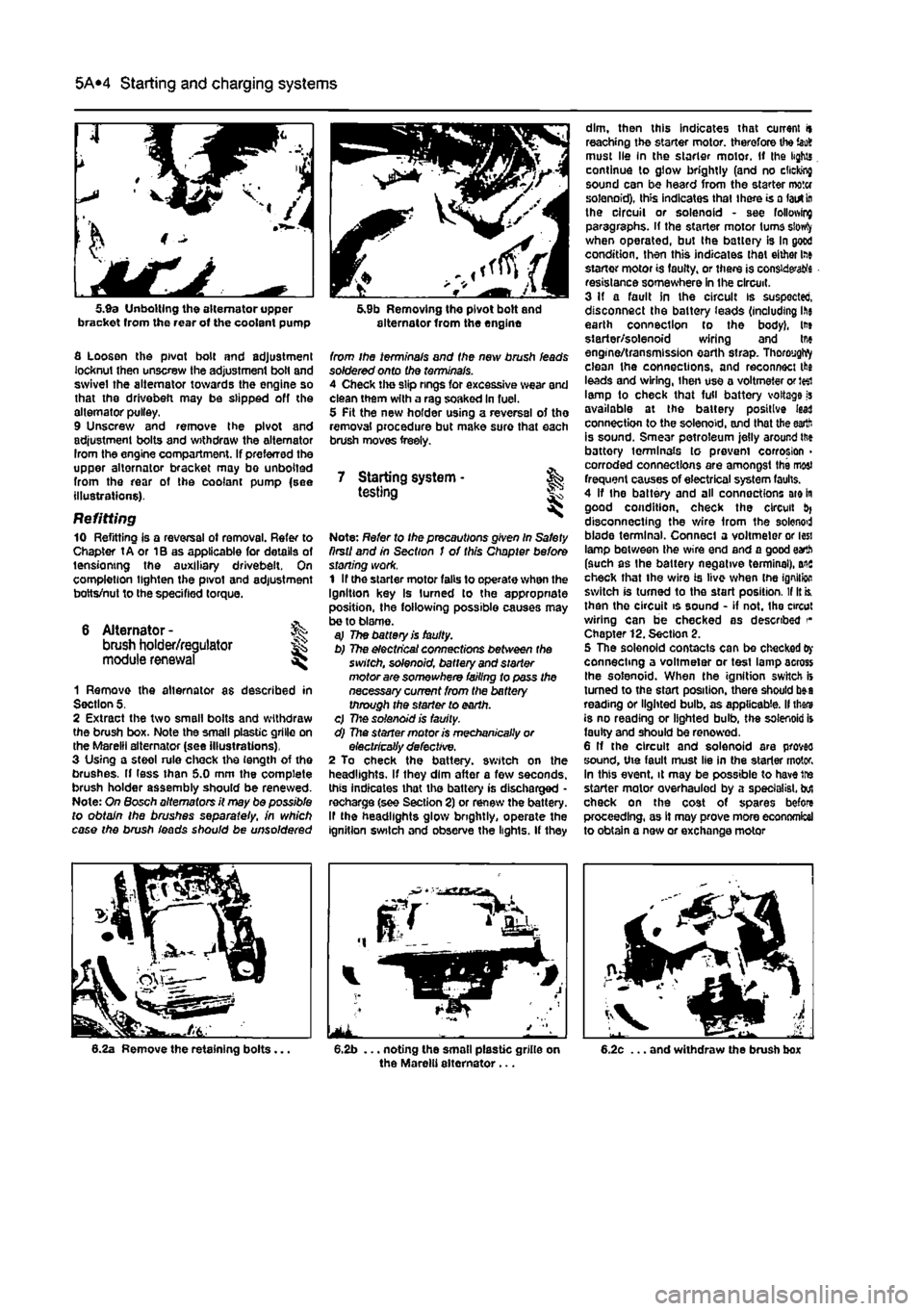
fl Loosen the pivot bolt and adjustment locknut then unscrew the adjustment bolt and swivel the alternator towards the engine so that the drivebefi may be slipped off the alternator pulley. 9 Unscrew and remove the pivot and adjustment bolts and withdraw the alternator Irom the engine compartment. If preferred the upper alternator bracket may bo unbolted from the rear of the coolant pump {see illustrations).
Refitting 10 Refitting is a reversal ot removal. Refer to Chapter tA or 1B as applicable for details of tensioning the auxiliary drivebeit. On completion lighten the pivot and adjustment botts/nut to the specified torque.
6 Alternator -brush holder/regulator module renewal
%
1 Remove the alternator as described in Section 5. 2 Extract the two small bolts and withdraw the brush box. Note the small plastic grille on the Marelli alternator (see illustrations), 3 Using a steol rule chock the length of the brushes. If less than 5.0 mm the complete brush holder assembly should be renewed. Note: On Bosch alternators it may be possible to obtain the brushes separate//, in which case the brush ieads should be unsoldered
5.9b Removing the pivot bolt and alternator from the engine
from ihe terminals and the new brush leads soldered onto the terminals. 4 Check the slip rings for excessive wear and clean them with a rag soaked in fuel. 5 Pit the new holder using a reversal of the removal procedure but make sure that each brush moves freely.
7 Starting system • & testing
Note: Refer to Ihe precautions given In Safety firstI and in Section I of this Chapter before stoning work. 1 If the starter motor falls to operate when the Ignition key Is turned to the appropriate position, the following possible causes may be to blame. aj The battery is faulty. b) The electrical connections between the switch, solenoid, battery and starter motor are somewhere failing to pass the necessary current from the battery through the starter to earth. c) 77:© solenoid is faulty. d) The starter motor is mechanically or electrically defective. 2 To check the battery, switch on the headlights. If they dim after a few seconds, this indicates that the battery is discharged -recharge (see Section 2) or renew the battery. If the headlights glow brightly, operate the ignition switch and observe the lights. If they
dim, then this indicates that current it reaching the starter motor, therefore the iao8 must lie In the starter motor. If the lights continue to glow brightly (and no clicking sound can be heard from the starter motor solenoid), this indicates that there is a lairt
In
the circuit or solenoid - see following paragraphs, if the starter motor turns siowfy when operated, but the battery is In good condition, then this indicates that either lae starter motor is faulty, or there is considers resistance somewhere in the circuit. 3 If a fault in the circuit is suspected, disconnect the battery ieads (including ihe earth connection to the body), lt» starter/solenoid wiring and tne engine/transmission earth strap. ThoroygWy clean the connections, and reconnect the leads and wiring, ihen use a voltmeter or J«i lamp to check that full battery voltage is available at the battery positive lead connection to the solenoid, and that the earth is sound. Smear petroleum jelly around ttie battory terminals to prevent corrosion > corroded connections are amongst the most frequent causes of electrical system faults. 4 If the battery and all connections are in good condition, check the circuit disconnecting the wire from the solenod blade terminal. Connect a voltmeter or less lamp between the wire end and a good earth (such as the battery negative terminal), ais check that the wire is live when tne ignition switch is turned to the start position. If It is. then the circuit is sound - if not. the circut wiring can be checked as described Chapter 12. Section 2. 5 The solenoid contacts can be checked
Oy
connecting a voltmeter or test lamp across Ihe solenoid. When the ignition switch is turned to the start position, there should b»a reading or lighted bulb, as applicable. II thars is no reading or lighted bulb, the solenoid is faulty and should be renewed. 6 If the circuit and solenoid are proves sound, the fault must lie in the starter motor. In this event, it may be possible to have tre starter motor overhauled by a specialist, but check on the cost of spares before proceeding, as It may prove more economical to obtain a new or exchange motor
Page 156 of 225
501
Chapter 5 PartC:
Preheating system - diesel models
Contents
Glow plugs - removal, inspection and refitting 2 Preheating system - description and testing 1 Preheating system control unit - removal and refitting 3
Degrees of difficulty
Ea3y, suitable
for &
novice with little
|| experience ^
Fairty easy,
suitable for beginner with
some experience
jQ
Fairty diffctit, ^
suitable
for competent
DIY
mechanic
Difficult, suitable for
experienced DIY JR mechanic ^
Very difficult, ^ suitable fbrexpertDfY JR or professional ^
Specifications
Torque wrench setting Nm ibf ft Heater glow plugs 15 11
1 Preheating system -description and testing
Description 1 Each swirl chamber has a heater plug (commonly called a glow plug) screwed into it. The plugs are electrically-operated before and during start-up when the engine is cold. 2 Electrical feed to the glow plugs Is controlled by a relay/timer unit. The coolant temperature determines the period of heating that takes place. 3 A warning light in the instnjment panel tells the driver that preheating is taking place. When the light goes out, the engine is ready to be started. The voltags supply to the glow plugs continues for several seconds after the light goes out, If no attempt is made to start, the timer then cuts off the supply, In order to avoid draining the battery and overheating the glow plugs.
Testing 4 If the system malfunctions, testing is ultimately by substitution of known good units, but some preliminary checks may be made as follows. 5 Connect a voltmeter or 12-volt test lamp between the glow plug supply cable and earth (engine or vehicle metal). Make sure that the live connection is kept clear of the engine and bodywork. 6 Have an assistant switch on the ignition, and check that vottage is applied to the glow plugs. Note the time for which the warning light Is lit. and the total time for which voltage Is applied before the system cuts out. Switch off the ignition. 7 At an under-bonnet temperature of 20°C. typical times noted should be 5 or 6 seconds for warning light operation, followed by a further 10 seconds supply after the light goes out. Warning light time will increase with lower temperatures and decrease with higher temp-eratures.
8 If there Is no supply at all, the relay or associated winng is at fault. 9 To locate a defective glow plug, disconnect the main supply cable and the interconnecting strap from the top of the glow plugs. Be careful not to drop the nuts and washers. 10 Use a continuity tester, or a 12-voH test lamp connected to the battery positive terminal, to check for continuity between each glow plug terminal and earth. The resistance of a glow plug in good condition is very low (less than 1 ohm), so if the test lamp does not light or the continuity tester shows a high resistance, the glow plug is certainly defective. 11 If an ammeter is available, the current draw of each glow plug can be checked. After an initial surge of 15 to 20 amps, each plug should draw approximately 12 amps. Any plug which draws much more or less than this is probably defective. 12 As a final check, the glow plugs can be removed and Inspected as described in the following Section.
Page 168 of 225
Automatic transmission 7B*3
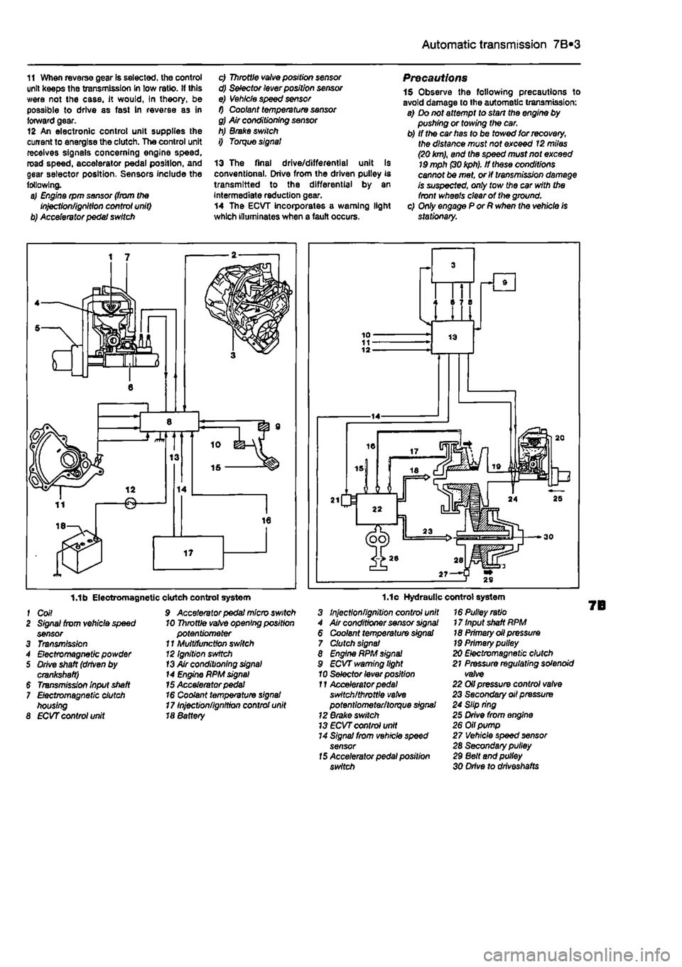
11 When reverse gear Is selected, the control unit keeps the transmission In tow ratio, if this were not the case, it would, In theory, be possible to drive as fast In reverse as in forward gear. 12 An electronic control unit supplies the current to energise the clutch. The control unit receives signals concerning engine speed, road speed, accelerator pedal position, and gear selector position, Sensors include the following. a) Engine rpm sensor (from the Injection/ignition control unit) b) Accelerator pedal switch
c) Throttle valve position sensor d) Selector lever position sensor e) Vehicle speed sensor f) Coolant temperature sensor g) Air conditioning sensor h) Brake switch I) Torque signal
13 The final drive/differential unit Is conventional. Drive from the driven pulley is transmitted to the differential by an Intermediate reduction gear. 14 The ECVT incorporates a warning light which illuminates when a fault occurs.
Precautions 1$ Observe the following precautions to avoid damage to the automatic transmission: a) Do not attempt to start the engine by pushing or towing the car. b) If the car has to be towed for recovery, the distance must not exceed 12 miles (20
km),
and the speed must not exceed
19
mph
(30 kph).
If these conditions cannot be met, or If transmission damage is suspected, only tow the car with the front wheels clear of the ground. c) Only engage P or R when the vehicle is stationary.
1.1b Electromagnetic f Coil 2 Signal from vehicle speed sensor 3 Transmission 4 Electromagnetic powder 5 Drive shaft (driven by crankshaft) $ Transmission input shaft 7 Electromagnetic clutch housing 8 ECVT control unit
clutch control system 9 Accelerator pedal micro switch 10 Throttle
vafve
opening position potentiometer 11 Multifunction switch 12 Ignition switch
13
Air conditioning
signal
14 Engine PPM
signal
15 Accelerator pedal 16 Coolant temperature signal 17 Injection/ignition control unit 18 8attery
1.1c Hydraulic control system 3 Injection/ignition control unit 4 Air conditioner sensor
signal
6 Coolant temperature signal 7 Clutch signal 8 Engine RPM
signal
9 ECVT warning light 10 Selector lever position 11 Accelerator
pedal
switch/throttle
valve
potentiometer/torque signal 12 Brake switch 13
ECVT
control unit 14 Signal from vehicle speed sensor
15
Accelerator pedal position switch
16 Pulley ratio 17 Input shaft RPM 18 Primary oil pressure
19
Primary pulley 20 Electromagnetic clutch 21 Pressure regulating solenoid valve 22 Oil pressure control valve 23 Secondary oil pressure 24 Slip ring 25 Drive from engine 26 Oil pump 27 Vehicle speed sensor 28 Secondary pulley 29 Belt and pulley 30 Drive to drlveshafts