evap FIAT PUNTO 1994 176 / 1.G Workshop Manual
[x] Cancel search | Manufacturer: FIAT, Model Year: 1994, Model line: PUNTO, Model: FIAT PUNTO 1994 176 / 1.GPages: 225, PDF Size: 18.54 MB
Page 20 of 225
1A»1
Chapter
1
Part A:
Routine maintenance & servicing - petrol models
Contents
Air
filter renewal 18 Automatic transmission filter and fluid change 2B Auxiliary dr
and filter renewal 3 Evaporative loss system check 27 Exhaust system check 8 From brake pad check 5 Fuel filter renewal 17 Headlight beam adjustment 23 Hinge and lock lubrication 22
Hose and fluid leak check 7 Idle speed and CO content check and adjustment .11 Ignition system check 20 Introduction 1 Lambda/oxygen sensor check 25 Manifold mounting check 16 Manual transmission oil level check 26 Manual transmission oil renewal .32 Pollen filter renewal 10 Rear brake shoe check 29 Regular maintenance 2 Road test 24 Spark plug renewal 19 Steering and suspension check 12 Timing belt renewal 30 Underbody sealant check 6 Valve clearance check and adjustment 15
Degrees of difficulty
Easy, suitable for ^ novice with little experience ^
Fairty easy, suitable for beginner with ^ some experience
FaMy difficult, ^ sitable for competent jj^ DIY mechanic ^
Difficult, suitable for experienced DIY aJ mechanic ^
Very difficult, ^ suitable for expert DIY or professional ^
expert22 fl/ia http://rutracker.org
Page 22 of 225
Maintenance schedule - petrol models 1A.3
The maintenance Intervals in this manual are provided with the assumption that you, not the dealer, will be carrying out the work. These axe the minimum maintenance intervals recommended by us for vehicles driven daily.
if you wish to keep your vehicle in peak condition at all times, you may wish to perform some of these procedures more often. We encourage frequent maintenance, because it enhances the efficiency.
performance and resale value of your vehicle. When the vehicle Is new, it should be serviced by a factory-authorised dealer service department, In order to preserve the factory warranty.
Every 250 miles (400 km) or weekly Q Refer to Weekly checks
Every 5000 miles (7500 km) or
6 months - whichever comes first • Renew the engine oil and filter (Section 3)
Note: Frequent oil and fitter changes am good tor the engine. We recommend changing the oil at the mileage specified here, or at least
twice
a year if the mileage covered Is a less.
Every 10 000 miles (15 000 km) or
12 months - whichever comes first
In
addition to the items listed above, cany out the following: Q Check the operation of the brake warning lamp (Section 4) • Check the front brake pads for wear (Section 5) • Check the underbody and sealant for damage (Section 6) • Hose and fluid leak check (Section 7) • Check the condition of the exhaust system and its mountings (Section 8) • Check the condition of the driveshaft gaiters (Section 9) • Renew pollen filter (Section 10) • Check exhaust gas content and idle speed (Section 11) • Check the steering and suspension components for condition and security (Section 12)
Every 20 000 miles (30 000 km) or
2 years - whichever comes first
In
addition to the Items listed above, carry out the following: • Check and if necessary adjust the tension of the auxiliary drlvebelt(s) (Section 13) • Check the freeplay and height of the clutch pedal (Section 14) • Check and if necessary adjust the valve clearances (Section 15) HI Check and if necessary tighten inlet and exhaust manifold mountings (Section 16) • Renew the fuel filter (Section 17) D Renew the air filter element (Section 18) O Renew the spark plugs (Section 19) • Check the condition of the HT cables (Section 20) • Check the engine management system (Section 21) Q Lubricate all hinges and locks (Section 22) O Check the headlight beam adjustment (Section 23) • Carry out a road test (Section 24)
Every 30 000 miles (45 000 km) or
3 years - whichever comes first In addition to the items listed above, cany out the following: • Check the operation of the Lambda sensor (Section 25) • Check and if necessary top-up the manual transmission oil level (Section 26) • Check the operation of the evaporative loss system (Section 27) • Automatic transmission inner filter and fluid renewal (Section 28)
Every 40 000 miles (60 000 km) or
4 years - whichever comes first In addition to the items fisted above, carry out the following: • Check the rear brake shoes for wear (Section 29) • Renew the timing belt (Section 30)"
*Noto: Although the normal interval for timing belt renewal is 70 000 miles (105 000 km), It is strongly recommended that the belt Is renewed at 40 000 miles (60 000 km) on vehicles which are subjected to Intensive use, ie. malniy short Journeys or a let of stop-start driving. The actual belt renewal Interval Is therefore very much up to the individual owner, but bear in mind that severe engine damage will result if the belt breaks.
Every 60 000 miles (90 000 km) or
6 years - whichever comes first in addition to the items listed above, cany out the following: • Check the condition and operation of the crankcase emission control system (Section 31)
Every 80 000 miles (120 000 km) • Renew the manual transmission oil (Section 32)
Every 2 years
(regardless of mileage) • Renew the engine coolant (Section 33) • Renew the brake fluid (Section 34)
Page 33 of 225
ia.14 Every 20 000 miles - petrol models
16 Test the operation of the brake servo unit as follows. With the engine off, depress the footbrake four or five times to exhaust the vacuum. Hold the brake pedal depressed, then start the engine. As the engine starts.
there should be a noticeable give In the brake pedal as vacuum builds up. Allow the engine to run for at least tsvo minutes, and then switch it off. If the brake pedal is depressed now. it should be possible to detect a hiss
from the servo as the pedal is depressed. After about four or five applications, no further hissing should be heard, and the pedal shouto feel considerably harder.
Every 30 000 miles (45 000 km) or 3 years
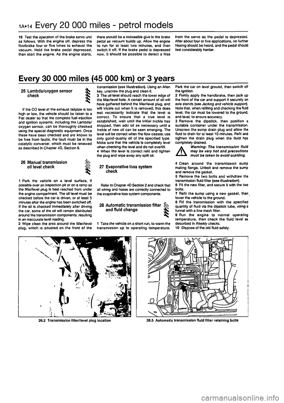
. transmission (see illustration). Using an Allen 25 Lambda/oxygen sensor ^ key, unscrew the plug and clean it. check \ 3 The oil level should reach the lower edge of ^ the filler/level hole. A certain amount of oil will have gathered behind the filler/level plug, and If the CO level at the exhaust tailpipe is too w,u tr,cWe out when is 'e™oved; this does high or low, Ihe vehicle should be taken to a «©l necessarily Indicate that the level is Fiat dealer so lhat the complete fuel-injection correct. To ensure that a true level is and ignition systems, including the Lamoda/ established, wait until the Initial trickle has oxygen sensor, can be thoroughly checked stopped, then ado oil as necessary until a using the special diagnostic equipment. Once ,r,ckle o1 new oil can be seen emerging. The these have been checked and are known to 'W wl" be correct when ,he flow ceases-us® be free from faults, the fault must be in the good-quality oil of the specified type, catalytic converter, which must be renewed Make sur®that vehicle Is completely level as described In Chapter 4D, Section 6. checking the level and do not overfill, 4 When the level Is correct refit and tighten the plug and wipe away any spilt oil.
26 Manual transmission oil level check ^ 27 Evaporative loss system ^ check
1 Park Ihe vehicle on a level surface, If possible over an inspection pit or on a ramp as the filler/level plug is best reached from under Ihe engine compartment. The oil level must be checked before the car is driven, or at least 5 minutes after the engine has been switched off. If the oil ts checked Immediately alter driving the car, some of the oil will remain distributed around the transmission components, resulting in an inaccurate level reading. 2 Wipe clean the area around the filler/level plug, which is situated on the front of the
Refer to Chapter 40 Section 2 and check that all wiring and hoses are correctly connected to the evaporative toss system components.
28 Automatic transmission fitter and fluid change
1 Take the vehicle on a short run. to warm the transmission up to operating temperature.
Park the car on level ground, then switch off the Ignition. 2 Firmly apply the handbrake, then jack up the front of the car and support It securely on axle stands (see Jacking and vehicle support]. Note thai, when refilling and checking Uie fluid level, the car must be lowered to the ground, and level, to ensure accuracy. 3 Remove the dipstick, then position a suitable container under the transmission, Unscrew the sump drain plug and allow the fluid to drain for at ieast 10 minutes. Refit and tighten the drain plug when the fluid has completely drained.
A
Warning: The transmission fluid may be very hot and precautions must be taken to avoid scalding.
4 Clean around the transmission sump mating flange. Unboll and remove the sump and remove the gasket. 5 Remove the two bolts and withdraw the transmission fluid filter {see illustration). 6 Fit the new filter, and secure It with the two bolts. 7 Refit the sump using a new gasket, then
_
lower the vehicle to the ground, 8 Fill the transmission with the specified quantity of fluid via Ihe dipstick tube, using a funnel with a fine mesh filter. 9 Run the engine to normal operating temperature, then check the fluid level as described In Weekly checks. 10 Dispose of the old fluid safely.
26.2 Transmission filler/level plug location 28.5 Automatic transmission fluid filter retaining bolts
Page 65 of 225
2B*5 DOHC (16-valve) petrol engine in-car repair procedures
4.11a Release the crankshaft TDC sensor wiring from the clip on the upper timing cover... throttle potentiometer and the Idle control stepper motor. Disconnect the coolant temperature sensor wiring connector located
in
the inlet manifold below the throttle body,
end
disconnect the brake servo vacuum hose. 15 Disconnect the wiring connectors for the fuel injector harness and the intake air temperature/pressure sensor, then fcconnect the fuel pressure regulator vacuum hose and the EVAP purge valve hose. 18 Undo the two bolts securing the plastic mlet manifold upper section to the lower section. Release the spark plug HT lead from the location groove in the manifold upper wctton, then lift the upper section, complete
»ith
throttle body, off the engine. Recover the 0-rngs from the manifold ports. 17 Unscrew the two bolts securing the fuel
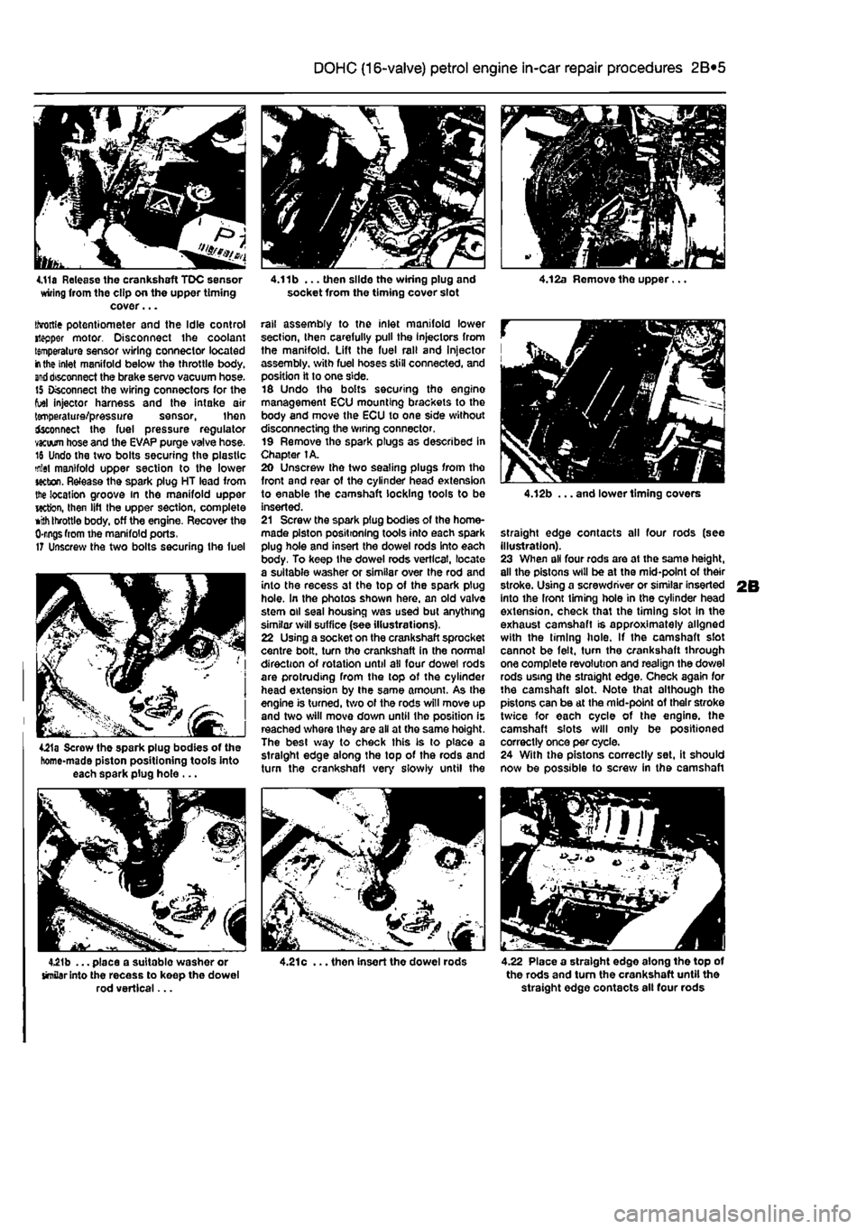
4£1a Screw the spark plug bodies of the homo-made piston positioning tools into each spark plug hole ...
4.21b ... place a suitable washer or similar into the recess to keep the dowel rod vertical...
4.11b ... then slide the wiring plug and socket from the timing cover slot
rail assembly to the inlet manifold lower section, then carefully pull the Injectors from the manifold. Lift the fuel rail and Injector assembly, with fuel hoses still connected, and position it to one side. 16 Undo the bolts securing the engine management ECU mounting brackets to the body and move the ECU to one side without disconnecting the wiring connector. 19 Remove the spark plugs as described in Chapter 1A. 20 Unscrew the two sealing plugs from the front and rear of the cylinder head extension to enable the camshaft locking tools to be inserted. 21 Screw the spark plug bodies of the home-made piston positioning tools into each spark plug hole and insert the dowel rods into each body. To keep the dowel rods vertical, locate a suitable washer or similar over Ihe rod and into the recess at the top of the spark plug hole. In the photos shown here, an old valve stem oil seal housing was used but anything similar will suffice (see illustrations). 22 Using a socket on the crankshaft sprocket centre bolt, turn the crankshaft in the normal direction of rotation until all four dowel rods are protruding from the top of the cylinder head extension by the same amount. As the engine is turned, two of the rods will move up and two will move down until the position is reached where they are all at the same hoight. The best way to check this is to place a straight edge along the top of the rods and turn the crankshafl very slowly until the
4.21c ... then insert the dowel rods
4.12b ... and lower timing covers
straight edge contacts all four rods (see illustration). 23 When all four rods are at the same height, all the pistons will be at the mid-point of their stroke. Using a screwdriver or similar inserted into the front timing hole in the cylinder head extension, check that the timing slot in the exhaust camshaft is approximately aligned with the liming hole. If the camshaft slot cannot be felt, turn the crankshaft through one complete revolution and realign the dowel rods using the straight edge. Check again for the camshaft slot. Note that although the pistons can be at the mid-point of their stroke twice for each cycle of the engine, the camshaft slots will only be positioned correctly once per cycle. 24 With the pistons correctly set, it should now be possible to screw in the camshaft
4.22 Place a straight edge along the top of the rods and turn the crankshaft until the straight edge contacts ail four rods
Page 67 of 225
2B*7 DOHC (16-valve) petrol engine in-car repair procedures
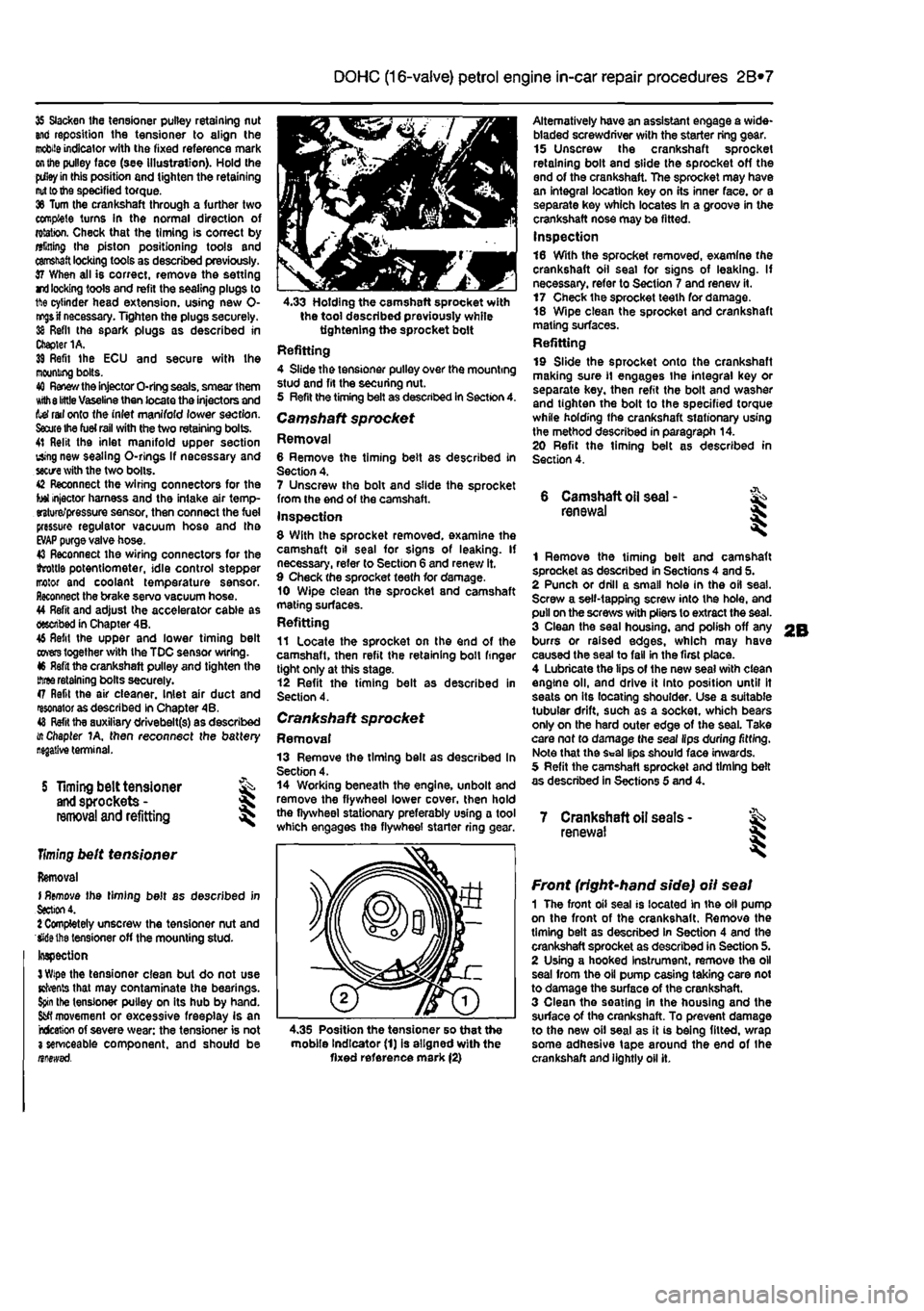
35 Slacken the tensioner pulley retaining nut and reposition the tensioner to align the
mobile
indicator with the fixed reference mark
on the
pulley face (see illustration). Hold the
pdley in
this position and tighten the retaining
nut to the
specified torque. 36 Turn the crankshaft through a further two complete turns In the normal direction of rotation. Check that the timing is correct by alining Ihe piston positioning tools and
camshaft
locking tools as described previously. 37 When all is correct, remove the setting rri
locking
tools and refit the sealing plugs to 1ft© cylinder head extension, using new 0-
nr^s if
necessary. Tighten the plugs securely. 38 Refit the spark plugs as described in Chapter 1A. 39 Refit Ihe ECU and secure with Ihe mooning bolts. 40
Renew the
injector O-ring seals, smear them Kith
8 little
Vaseline then locate the injectors and tef rail onto the inlet manifold lower section.
Saute Ihe fuel rail
with the two retaining bolts. 41 Relit the inlet manifold upper section using new sealing O-rlngs If necessary and
sectre
with the two bolts. 42 Reconnect the wiring connectors for the tot injector harness and the intake air temp-erature/pressure sensor, then connect the fuel pressure regulator vacuum hose and tha
EVAP
purge valve hose. 43 Reconnect the wiring connectors for the ihrottls potentiometer, idle control stepper motor and coolant temperature sensor. Reconnect the brake servo vacuum hose. 44 Refit and adjust the accelerator cable as described in Chapter 4B. 46 Refit the upper and lower timing belt
covers
together with the TDC sensor wiring. 46 Refit the crankshaft pulley and tighten the
three
retaining bolts securely. 47 Refit the air cleaner. Inlet air duct and resonator as described in Chapter 4B. 48
Refit
tha auxiliary drivebelt(s) as described i/t Chapter 1A, then reconnect the battery
S Timing belt tensioner
and
sprockets -
removal
and refitting
Timing
belt tensioner
Removal I
Remove
the timing belt as described in
Section
4. 1 Completely unscrew the tensioner nut and Wiethe tensioner off the mounting stud-Inspection
3 Wipe
the tensioner clean but do not use Kfrents that may contaminate the bearings.
Spin
the tensioner pulley on its hub by hand.
Sfcfl
movement or excessive freeplay is an rcfceticn of severe wear: the tensioner is not 3 serviceable component, and should be nnewsd.
4.33 Holding the camshaft sprocket with the tool described previously while tightening the sprocket bolt Refitting 4 Slide the tensioner pulley over the mounting stud and fit the securing nut. 5 Refit the timing belt as described in Section 4. Camshaft sprocket Removal 6 Remove the timing belt as described in Section 4. 7 Unscrew the bolt and slide the sprocket from the end of the camshaft. Inspection 8 With the sprocket removed, examine the camshaft oil seal for signs of leaking. If necessary, refer to Section 6 and renew it. 9 Check the sprocket teeth for damage. 10 Wipe clean the sprocket and camshaft mating surfaces. Refitting 11 Locate the sprocket on the end of the camshaft, then refit the retaining boll finger tight only at this stage. 12 Refit the timing belt as described in Section 4.
Crankshaft sprocket Removal 13 Remove the timing bell as described In Section 4. 14 Working beneath the engine, unbolt and remove the flywheel lower cover, then hold the flywheel stationary preferably using a tool which engages the flywheel starter ring
<
Alternatively have an assistant engage a wide-bladed screwdriver with the starter ring gear. 15 Unscrew the crankshaft sprocket retaining bolt and slide the sprocket off the end of the crankshaft. The sprocket may have an integral location key on its inner face, or a separate key which locates In a groove in the crankshaft nose may be fitted. Inspection 16 With the sprocket removed, examine the crankshaft oil seal for signs of leaking. If necessary, refer to Section 7 and renew it. 17 Check the sprocket teeth for damage. 18 Wipe clean the sprocket and crankshaft mating surfaces. Refitting 19 Slide the sprocket onto the crankshaft making sure
11
engages the integral key or separate key, then refit the bolt and washer and tighten the bolt to the specified torque while holding the crankshaft stationary using the method described in paragraph 14. 20 Refit the timing belt as described in Section 4.
6 Camshaft
oil
seal -renewal
1 Remove the timing belt and camshaft sprocket as described in Sections 4 and 5. 2 Punch or drill a small hole in the oil seal. Screw a self-tapping screw into the hole, and pull on the screws with pliers to extract the seal. 3 Clean the seal housing, and polish off any burrs or raised edges, which may have caused the seal to fall in the first place. 4 Lubricate the lips of the new seal with clean engine oil, and drive it into position until It seats on its locating shoulder. Use a suitable tubular drift, such as a socket, which bears only on the hard outer edge of the seal. Take care nof to damage the seal lips during fitting. Note that the Seal lips should face inwards. 5 Refit the camshaft sprocket and timing belt as described in Sections 5 and 4.
7 Crankshaft oil seats -renewal I
4.35 Position the tensioner so that the mobile Indicator (1) is aligned with the fixed reference mark (2)
Front (right-hand side) oil seal 1 The front oil seal is located in the oil pump on the front of the crankshaft. Remove the timing belt as described in Section 4 and the crankshaft sprocket as described in Section 5. 2 Using a hooked Instrument, remove the oil seal from the oil pump casing taking care not to damage the surface of the crankshaft. 3 Clean the seating in the housing and the surface of the crankshaft. To prevent damage to the new oil seal as it is being fitted, wrap some adhesive tape around the end of the crankshaft and lightly oil it.
Page 119 of 225
3*2 Cooling, heating and ventilation systems
Heater matrix Removal 10 Remove the complete heater assembly as described previously in this Section. 11 Slacken and remove the securing screws, then withdraw the heater matrix from the tester assembly casing. Refitting 12 Refitting is a reversal of removal; refit Ihe neater assembly as described previously in
this
Section.
Heater blower motor
Removal 13 Disconnect the battery negative terminal {refer to Disconnecting the battery in the Reference Section of this manual). 14 Unplug the wiring from the blower motor
al the
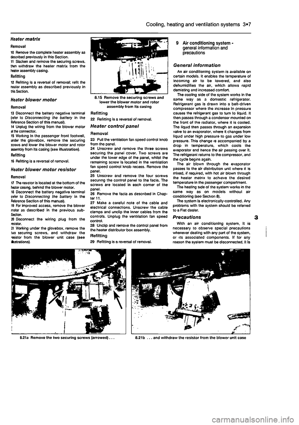
connector. 15 Working in the passenger front footwell, under the glovebox. remove the securing grows and lower the blower motor and rotor assembly from Its casing (see illustration). Refitting
16 Refitting is a reversal of removal.
Heater blower motor resistor
Removal 17 The resistor is located at the bottom of the heater casing, behind the blower motor. 18 Disconnect the battery negative terminal (refer to O/sconnecf/ng the battery in the Reference Section of this manual). 19 For improved access, remove the blower motor as described in the previous sub-Section. 20 Disconnect the wiring plug from the resistor. 21 Working under the glovebox. remove the two securing screws, and withdraw the resistor from the blower unit case (see lustrations).
8.15 Removo the securing screws and lower the blower motor and rotor assembly from its casing Refitting 22 Refining Is a reversal of removal.
Heater control panel
Removal 23 Pull the ventilation fan speed control knob from the panel. 24 Unscrew and remove the three screws securing the panel cover. Two screws are under the lower edge of the panel, whilst Ihe remaining screw is located in the ventilation fan speed control knob recess. Remove the panel. 25 Unscrew and remove the four screws securing the control panel to the facia. The screws are located in each comer of the panel. 26 Remove the facia as described in Chap-ter 11. 27 Make a careful note of the cable and electrical connections. Unscrew the cable clamps and unclip the inner cables from the controls. Unplug the ventilation fan speed control. 28 Unclip and remove the control panel from the heater distributor box assembly. Refitting 29 Refitting is a reversal of removal.
9 Air conditioning system -general Information and precautions
General information An air conditioning system is available on certain models. It enables the temperature of Incoming air to be lowered, and also dehumidifies the air, which allows rapid demisting and increased comfort. The cooling side of the system works In the same way as a domestic refrigerator. Refrigerant gas is drawn into a belt-driven compressor where the increase In pressure causes the refrigerant gas to turn to liquid. It then passes through a condenser mounted on the front of the radiator, where it is cooled. Tho liquid then passes through an expansion vaive to an evaporator, where it changes from liquid under high pressure to gas under low pressure. This change is accompanied by a drop in temperature, which cools the evaporator and hence the air passing over it. The refrigerant returns to the compressor, and the cycle begins again. The air bfown through the evaporator passes to the air distribution unit where it is mixed, if required, with hot air blown through the heater matrix to achieve the desired temperature in the passenger compartment. The heating side of ihe system works in the same way as on models without air conditioning (see Section 8). The system Is electronically-controlled. Any problems with the system should be referred to a Fiat dealer.
Precautions With an air conditioning system. It is necessary to observe special precautions whenever dealing with any part of the system, or its associated components. If for any reason the system must be disconnected, it Is
8.21a Remove the two securing screws (arrowed)... ,21b ... and withdraw the resistor from the blower unit case
Page 122 of 225
4A*2 Fuel system - single-point petrol Injection models
1 General information and precautions
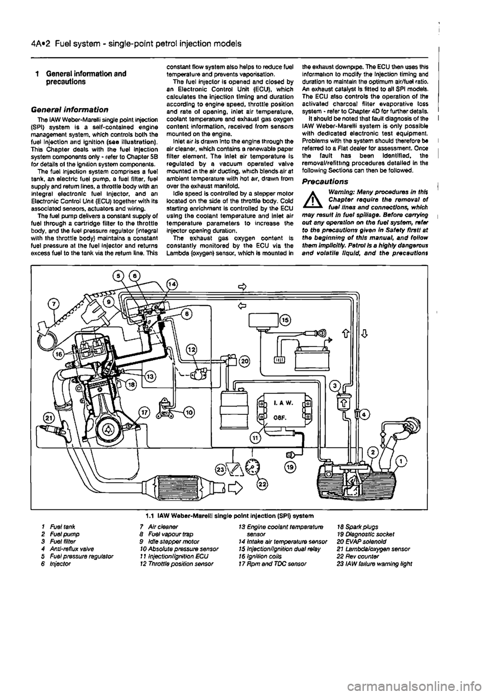
General information The iAW Weber-Marelli single point Injection (SPI) system is a self-contained engine management system, which controls both the fuel Injection and Ignition (see Illustration), This Chapter deals with the fuel Injection system components only - refer to Chapter 5B for details ol the ignition system components. The fuel Injection system comprises a fuel tank, an electric fuel pump, a fuel filter, fuel supply and return lines, a throttle body with an integral electronic fuel Injector, and an Electronic Control Unit (ECU) together with its associated sensors, actuators and wiring. The fuel pump delivers a constant supply of fuel through a cartridge fitter to the throttle body, and the fuel pressure regulator (integral with the throttle body) maintains a constant fuel pressure at the fuel injector and returns excess fuel to the tank via the return line. This
constant flow system also helps to reduce fuel temperature and prevents vaporisation. Tne fuel injeclor Is opened and closed by an Electronic Control Unit (ECU), which calculates the injection timing and duration according to engine speed, throttle position and rate of opening, Inlet air temperature, coolant temperature and exhaust gas oxygen content information, received from sensors mounted on the engine. inlet air is drawn Into the engine through the air cleaner, which contains a renewable paper filter element. The inlet air temperature is regulated by a vacuum operated valve mounted in the air ducting, which blends air at ambient temperature with hot air, drawn from over the exhaust manifold. Idle speed is controlled by a stepper motor located on the side of the throttle body. Cold starling enrichment is controlled by the ECU using the coolant temperature and inlet air temperature parameters to increase the injector opening duration. The exhaust gas oxygen content is constantly monitored by the ECU via the Lambda (oxygen) sensor, which is mounted in
me exhaust downpipe. The ECU then uses this Information to modify the Injection timing and duration to maintain the optimum air/fuel ratio. An exhaust catalyst Is fitted to all SPI models. The ECU also controls the operation of the activated charcoal filter evaporative loss system • refer to Chapter 4D for further details. It should be noted that fault diagnosis of the I IAW Weber-Marelli system is only possible with dedicated electronic test equipment. Problems with the system should therefore be I referred to a Flat dealer for assessment. Once i the fault has been Identified, the I removal/refitting procedures detailed in the following Sections can then be followed.
Precautions |
A
Warning: Many procedures in thH Chapter require the removal ot fuel lines and connections, which may result in fuel spillage. Before carrying | out any operation on Me fuel system, refer to the precautions given In Safety flrstt at the beginning ot this manual, and follow them Implicitly. Petrol Is a highly dangerous and volatile liquid, and the precautions
1.1 IAW Weber-Marelli single point Injection (SPI) system 1 Fuel
tank
2 Fuel pump 3 Fuel filter 4 Anii'reflux valve 5 Fuel pressure regulator 6 Injector
7 Air cleaner 8 Fuel vapour
trap
9 Idle stepper motor
10
Absolute pressure sensor J11njection/ignition ECU 12 Tnrottle position sensor
13 Engine coolant temperature sensor 14 Intake air temperature sensor 15 Inject'onfignitron dual
relay
16 Ignition coils 17 Rpm and TDC sensor
18 Spark plugs 79 Diagnostic socket 20 EVAP solenoid 21 Lambda/oxygen sensor 22 Rev counter 23 IAW failure warning light
Page 123 of 225
4A*2 Fuel system - single-point petrol Injection models
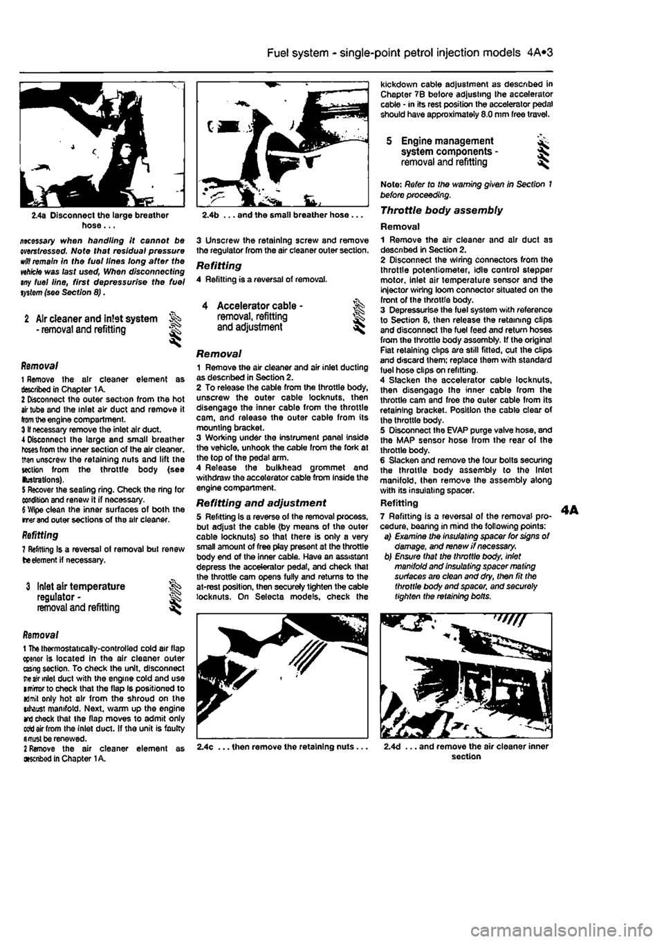
2.4a Disconnect the large breather hose... ziecessary when handling it cannot be mrstressed. Note that residual pressure
wttf
remain in the tuei lines long after the wh/cte was last used, When disconnecting any fuel line, first depressurise the fuel
system
(see Section 8).
2 Air cleaner and intet system • removal and refitting
1
Accelerator cable -removal, refitting and adjustment l
Removal 1 Remove the air cleaner element as described in Chapter 1A. 2 Disconnect the outer section from the hot
air
tube and the inlet air duct and remove it
from
the engine compartment. 3II necessary remove the inlet air duct. 4 Disconnect Ihe large and small breather
roses
from the inner section of the air cleaner, tftsn unscrew the retaining nuts and lift the section from the throttle body (see lustrations).
5
Recover the sealing ring. Check the ring for condition and renew it if necessary.
6
Wipe clean the inner surfaces of both the merand outer sections of the air cleaner. Refitting 7 Refitting Is a reversal ol removal but renew
tie
element
H
necessary.
3 Inlet air temperature regulator -removal and refitting
Removal t
The
thermostatically-controlled cold air flap cpener is located in the air cleaner outer ttsrig section. To check the unit, disconnect
ire air
inlet duct with the engine cold and use imrrorto check that the flap Is positioned to aJmit only hot air from the shroud on the utaust manifold. Next, warm up the engine
and
check that the flap moves to admit only sett air from the inlet duct. If the unit is faulty fl must be renewed.
2
Remove the air cleaner element as •senbod in Chapter
1
A.
kickdown cable adjustment as described in Chapter 7B before adjusting the accelerator cable • in its rest position the accelerator pedal should have approximately 8.0 mm free travel.
5 Engine management system components -removal and refitting I
2.4b ... and the small breather hose ...
3 Unscrew the retaining screw and remove the regulator from the air cleaner outer section.
Refitting 4 Refitting is a reversal of removal.
Removal 1 Remove the air cleaner and air inlet ducting as desenbed in Section 2. 2 To release the cable from the throttle body, unscrew the outer cable locknuts, then disengage the inner cable from the throttle cam, and release the outer cable from its mounting bracket. 3 Working under the instrument panel inside the vehicle, unhook the cable from the fork at the top of the pedal arm. 4 Release the bulkhead grommet and withdraw the accelerator cable from Inside the engine compartment.
Refitting and adjustment 5 Refitting is a reverse of the removal process, but adjust the cable (by means of the outer cable locknuts) so that there is only a very small amount of free play present at the throttle body end of the inner cable. Have an assistant depress the accelerator pedal, and check that the throttle cam opens fully and returns to the at-rest position, then secureJy tighten the cable locknuts. On Selecta models, check the
Note: Refer to the warning given in Section 1 before proceeding. Throttle body assembly
Removal 1 Remove the air cleaner and air duct as desenbed in Section 2. 2 Disconnect the wiring connectors from the throttle potentiometer, idle control stepper motor, inlet air temperature sensor and the injector wiring loom connector situated on the front of the throttle body. 3 Depressurise the fuel system with reference to Section 8, then release the retaining clips and disconnect the fuel feed and return hoses from the throttle body assembly, if the original Fiat retaining clips are still fitted, cut the clips and discard them; replace them with standard luel hose clips on refitting. 4 Slacken the accelerator cable locknuts, then disengage the inner cable from the throttle cam and froe tho outer cable from its retaining bracket. Position the cable clear of the throttle body. 5 Disconnect the EVAP purge valve hose, and the MAP sensor hose from the rear of the throttle body. 6 Slacken and remove the four bolts securing the throttle body assembly to tho Inlet manifold, then remove the assembly along with its insulating spacer. Refitting 7 Refitting is a reversal of the removal pro-cedure, bearing in mind the following points: a) Examine the insulating spacer for signs of damage, and renew //necessary, b) Ensure that the throttle body, inlet manifold and insulating spacer ma ting surfaces are clean and dry, then fit the throttle body and spacer, and securely tighten the retaining bolts.
2.4c ... then remove the retaining nuts. 2.4d ... and remove the air cleaner inner section
Page 125 of 225
Ihe right-hand front roadwheel and the protective plastic cover under the wheelarch. 37 Disconnect the sensor wiring plug on the front of the engine. 38 Detach the sensor from its mounting. Refitting 39 After refitting Ihe sensor use a feeler blade to check that the gap between sensor and the serrated part of the crankshaft pulley Is between 0.5 and 1.S mm. No adjustment is possible and if the gap is incorrect the sensor and pulley should be checked for possible damage.
Electronic control unit (ECU)
Removal Note: 77ie engine management system has a (earning capability which allows the ECU to store details of the engine's running
characteristics
in its memory,
This
memory
will
tie erased by the disconnection of the battery
cables,
with the resuit that the engine may idle
roughly,
or lack performance for a while, until
the
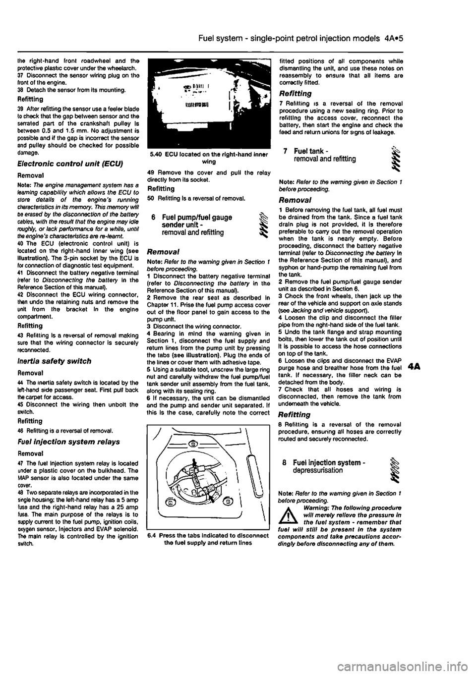
engine's characteristics are re-teamt. 40 The ECU {electronic control unit) is located on the right-hand Inner wing (see illustration). The 3-pin socket by the ECU is for connection of diagnostic test equipment. 41 Disconnect the battery negative terminal (refer to D/sconnecffng the battery in the Reference Section of this manual). 42 Disconnect the ECU wiring connector, then undo the retaining nuts and remove the unit from the bracket In the engine compartment. Refitting 43 Refitting Is a reversal of removal making sure that the wiring connector is securely reconnected. Inertia safety switch
Removal 44 The inertia safety switch is located by the left-hand side passenger seat. First pull back
the
carpet for access. 45 Disconnect the wiring then unbolt the switch. Refitting 48 Refitting is a reversal of removal.
Fuel injection system relays
Removal 47 The fuel injection system relay is located under a plastic cover on the bulkhead. The MAP sensor is also located under the same cover. 48 Two separate relays are incorporated in the single housing; the left-hand relay has a 5 amp fuse and the right-hand relay has a 25 amp fuse. The main purpose of the relays is to supply current to the fuel pump, ignition coils, oxygen sensor. Injectors and EVAP solenoid. The main relay is controlled by the ignition switch.
4A*2 Fuel system - single-point petrol Injection models
6 Fuel pump/fuel gauge sender unit -removal and refitting
Removal Note: Refer to the warning given in Section 1 before proceeding. 1 Disconnect the battery negative terminal (refer to Disconnecting the battery in the Reference Section of this manual). 2 Remove the rear seat as described in Chapter 11. Prise the fuel pump access cover out of the floor panel to gain access to the pump unit. 3 Disconnect the wiring connector. 4 Bearing in mind the warning given in Section t, disconnect the fuel supply and return lines from the pump unit by pressing the tabs (see illustration). Plug the ends of the lines or cover them with adhesive tape. 5 Using a suitable toot, unscrew the large ring nut and carefully withdraw the fuel pump/fuel tank sender unit assembly from the fuel tank, along with its sealing ring. 6 If necessary, the unit can be dismantled and the pump and sender unit separated. If this is the case, carefully note the correct
fitted positions of oil components while dismantling the unit, and use these notes on reassembly to ensure that all items are correctly fitted.
Refitting 7 Refitting is a reversal of the removal procedure using a new sealing ring. Prior to refitting the access cover, reconnect the battery, then start the engine and check the feed and return unions for signs of leakage.
5.40 ECU located on the right-hand inner wing 49 Remove the cover and pull the relay directly from its socket. Refitting 50 Refitting Is a reversal of removal.
7 Fuel tank -removal and refitting
6.4 Press the tabs Indicated to disconnect the fuel supply and return tines
Note: Refer to the warning given in Section 1 before proceeding.
Removal 1 Before removing the fuel tank, all fuel must be drained from the tank. Since a fuel tank drain plug is not provided, it is therefore preferable to carry out the removal operation when the tank is nearly empty. Before proceeding, disconnect the battery negative terminal (refer to Disconnecting the battery In the Reference Section of this manual), and syphon or hand-pump the remaining fuel from the tank. 2 Remove the fuel pump/fuel gauge sender unit as described in Section 6. 3 Chock the front wheels, then jack up the rear of the vehicle and support on axle stands (see Jacking and vehicle support). 4 Loosen the clip and disconnect the filler pipe from the nght-hand side of the fuel tank. 5 Undo the tank flange and strap mounting bolts, then lower the tank out of position until It is possible to access the hose connections on top of the tank. 6 Loosen the clips and disconnect the EVAP purge hose and breather hose from the fuel tank. If necessary, the filler neck can be detached from the body. 7 Check that all hoses and wiring is disconnected, then remove the tank from underneath the vehicle. Refitting 8 Refitting is a reversal of the removal procedure, ensuring all hoses are correctly routed and securely reconnected.
8 Fuel injection system - ^ depressurisation
Note: Refer to the warning given In Section t before proceeding.
A
Warning; The following procedure will merely relievo the pressure in the fuel system • remember that fuel will still be present In the system components and take precautions accor-dingly before disconnecting any of them.
Page 128 of 225
4A*2 Fuel system -
single-point
petrol Injection models
1 General information and precautions
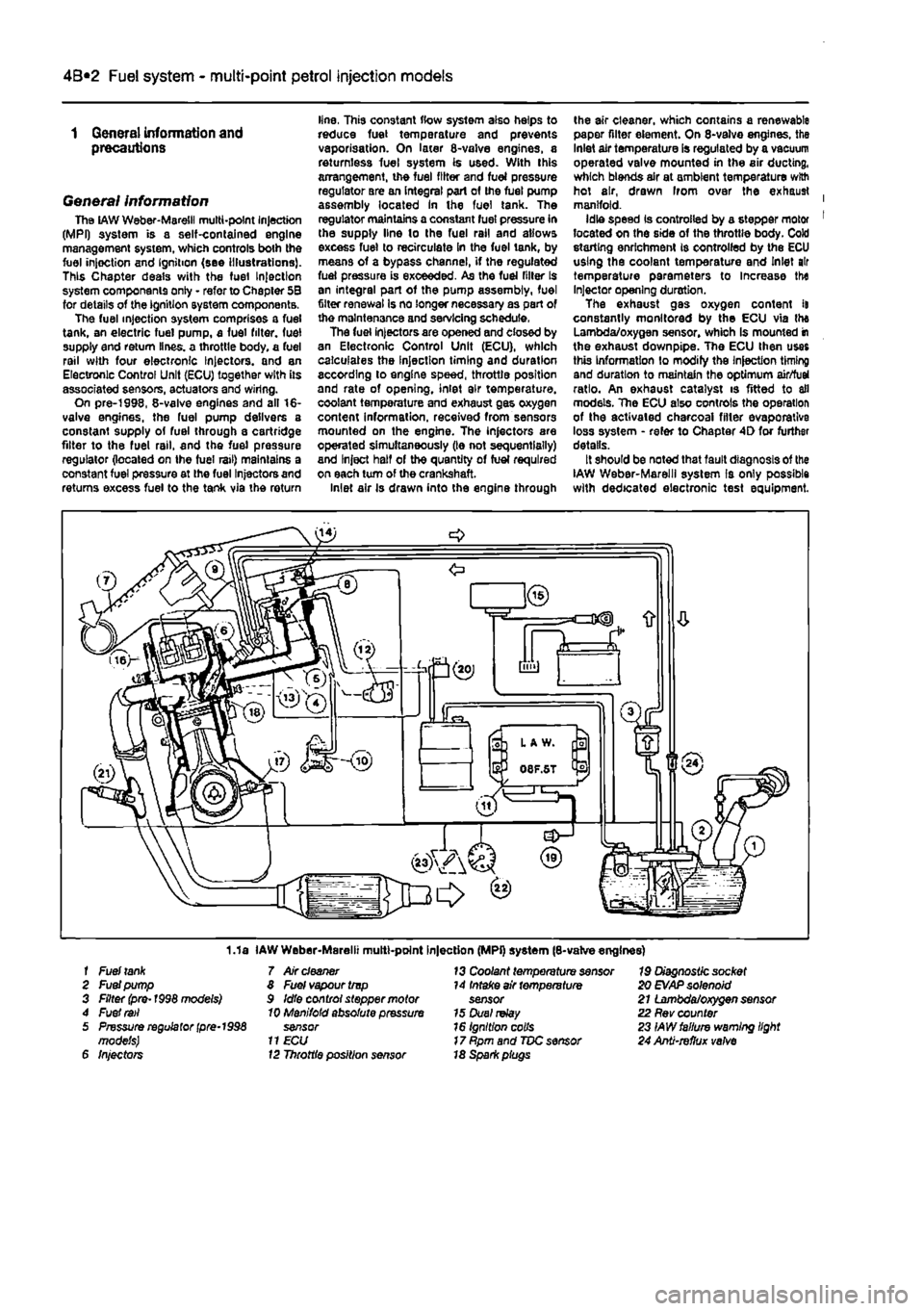
General information The
LAW
Weber-Maretil multi-point Injection (MPI) system is a self-contained engine management system, which controls both the fuel injoction and Ignition (see Illustrations). This Chapter deals with the fuel Injection system components only - refer to Chapter 5B for details of the ignition system components. The fuel injection system comprises a fuel tank, an electric fuel pump, a fuel filter, fuel supply end return lines, a throttle body, a fuel rail with four electronic Injectors, and an Electronic Control Unit (ECU) together with its associated sensors, actuators and wiring. On pre-1998, 8-valve engines and all 16-valve engines, the fuel pump delivers a constant supply of fuel through a cartridge filter to the fuel rail, and the fuel pressure regulator (located on Ihe fuel rail) maintains a constant fuel pressure at the fuel Injectors and returns excess fuel to the tank via the return
line, This constant flow system also helps to reduce fuel temperature and prevents vaporisation. On later 8-valve engines, a returnless fuel system is used. With this arrangement, the fuel filter and fuel pressure regulator are an integral part of the fuel pump assembly located In the fuel tank. The regulator maintains a constant fuel pressure in the supply line lo the fuel rail and allows excess fuel to recirculate in the fuel tank, by means of a bypass channel, if the regulated fuel pressure is exceeded. As the fuel filler Is an integral part of the pump assembly, fuel filter renewal Is no longer necessary as part of the maintenance and servicing schedule. The fuel injectors are opened and closed by an Electronic Control Unit (ECU), which calculates the Injection timing and duration according to engine speed, throttle position and rate of opening, inlet air temperature, coolant temperature and exhaust gas oxygen content information, received from sensors mounted on the engine. The injectors are operated simultaneously (le not sequentially) and Inject half of the quantity of fuel required on each turn of the crankshaft. Inlet air Is drawn into the engine through
the air cleaner, which contains a renewable paper filter element. On 8-valve engines, the Inlet air temperature is regulated by a vacuum operated valve mounted in the air ducting, which blends air at ambient temperature with hot air, drawn Irom over the exhaust | manifold. Idle speed Is controlled by a stepper motor 1 located on the side of the throttle body. Cold storting enrichment is controlled by the ECU using the coolant temperature and Inlet air temperature parameters to Increase the Injector opening duration. The exhaust gas oxygen content it constantly monitored by the ECU via the Lambda/oxygen sensor, whioh Is mounted in the exhaust downpipe. The ECU then uses this Information to modify the Injection timing and duration to maintain the optimum air/fuel ratio. An exhaust catalyst is fitted to all models. The ECU also controls the operation of the activated charcoal filler evaporative loss system - refer to Chapter 4D for further details. It should be noted that fault diagnosis of the IAW Weber-Marelll system Is only possible with dedicated electronic test equipment.
1.1a IAW Weber-Marelii multt-point Injection (MPi) system (8-valve engines) f Fuel
tank
7 Air
cleaner
13 Coolant temperature sensor 19 Diagnostic socket 2 Fuel pump 8 Fuel vapour trvp 14 Intake air temperature 20
EVAP
solenoid 3 Filter (pre-1998 models) 9 Idle control stepper motor sensor 21 Lambda/oxygen sensor 4 Fuel
rail
10 Manifold absolute pressure 15 Duel
relay
22 Rev counter 5 Pressure regulator
(pre-1998
sensor 16 Ignition colls 23 IAW failure warning light models)
11 ECU
17 Rpm and TDC sensor 24 Anti-refhjx
valve
6 Injectors 12 Throttle position sensor 18 Spark piugs