Starter FIAT PUNTO 1995 176 / 1.G Owner's Manual
[x] Cancel search | Manufacturer: FIAT, Model Year: 1995, Model line: PUNTO, Model: FIAT PUNTO 1995 176 / 1.GPages: 225, PDF Size: 18.54 MB
Page 152 of 225
5A«2 Starting and charging systems
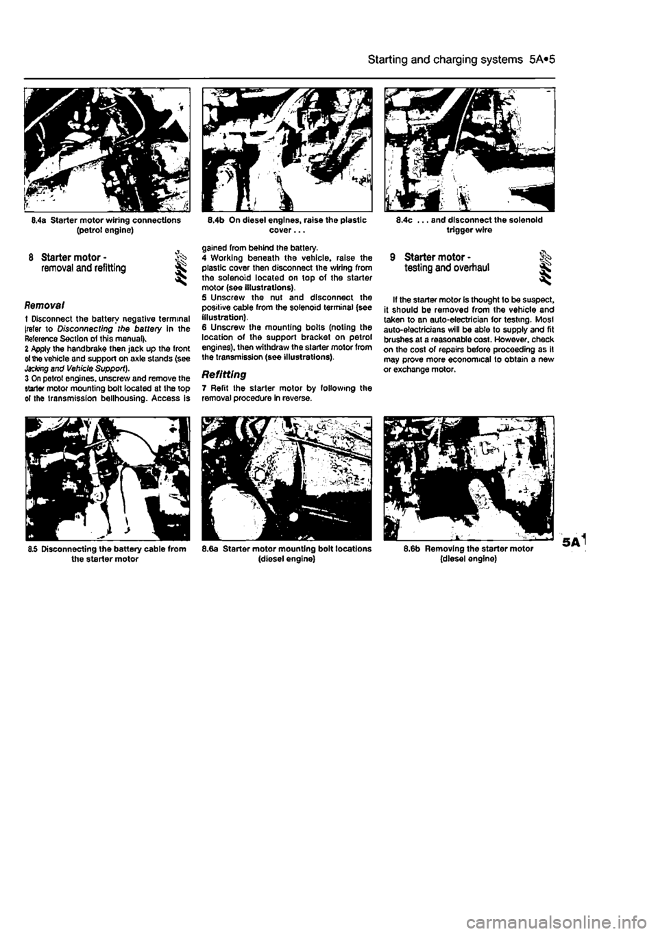
6.4a Starter motor wiring connections (petrol engine)
8 Starter motor -removal and refitting S
Removal t Disconnect the battery negative terminal [refer to Disconnecting the battery in the Reference Section of this manual). 2 Apply the handbrake then jack up the front
ol
the vehicle and support on axle stands (see
Jacking
and Vehicle Support). 3 On petrol engines, unscrew and remove the starter motor mounting bolt located at the top ol the transmission bellhousing. Access is
8.5 Disconnecting the battery cable from the starter motor
8.4b On diesel engines, raise the plastic cover...
gained from behind the battery. 4 Working beneath the vehicle, raise the plastic cover then disconnect the wiring from the solenoid located on top of the starter motor (see illustrations). 5 Unscrew the nut and disconnect the positive cable from the solenoid terminal (see illustration). 6 Unscrew the mounting bolts (noting the location of the support bracket on petrol engines), then withdraw the starter motor from the transmission (see illustrations).
Refitting 7 Refit the starter motor by following the removal procedure in reverse.
8.6a Starter motor mounting bolt locations (diesel engine)
8.4c ... and disconnect the solenoid trigger wire
9 Starter motor - ft* testing and overhaul ££
If the starter motor is thought lo be suspect, it should be removed from the vehicle and taken to an auto-electrician for testing. Most auto-electricians will be able to supply and fit brushes at a reasonable cost. However, check on the cost of repairs before proceeding as il may prove more economical to obtain a new or exchange motor.
8.6b Removing the starter motor (diesel engine)
Page 164 of 225
Manual transmission 7A*3
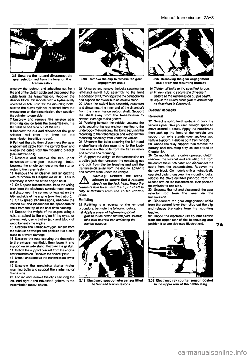
3,8 Unscrew the nut and disconnect the gear selector rod from the lever on the transmission unscrew the locknut and adjusting nut from the end of the clutch cable and disconnect the cable from the transmission. Recover the damper block. On models with a hydraulically operated clutch, unscrew the mounting bolts, release the slave cylinder pushrod from the re&ase arm on the transmission, then position the cylinder to one side.
7 Unscrew and remove the reverse gear Inhibiting device from the transmission. Tie the cable to one side out of the way. 8 Unscrew the nut and disconnect the gear selector rod from the lever on the transmission (see illustration). 9 Pull out the clip then disconnect the gear engagement cable from the control lever and release the cable from the mounting bracket (see illustrations). 10 Unscrew and remove the two upper transmisslon-to-englne mounting bolts. Unscrew the single bolt securing the starter motor to the transmission. 11 Remove the air cleaner and air ducting with reference to Chapter 4A or 4B. This Is necessary In order to fit the engine hoist 12 On 5-speed transmissions, trace the wiring back from the electronic speedometer sensor and disconnect the connector located on the left-hand side of the engine (see illustration). 13 On 6-speed transmissions, unscrew the knurled nut and disconnect the speedometer cable from the top of the final drive housing. 14 Support the weight of the engine using a hoist attached to the engine lifting eyes, or alternatively use a trolley jack and block of wood beneath Ihe engine. 15 Unscrew the Lambda/oxygen sensor from the exhaust downpipe and position It In a safe place to prevent damage. 16 Unscrew the nuts securing the downpipe to the exhaust manifold, then lower It and support on an axle stand. Recover the gasket. 17 Unbolt the support bracket from the engine and transmission. Recover the spacer plate. 18 Unbolt and remove the transmission lower cover, 19 Unscrew the remaining starter motor mounting bolts and support tho starter motor to one side. 20 Loosen and remove the clips securing the left- and right-hand driveshaft gaiters to the transmission output shafts.
3.9a Remove the clip to release the gear engagement cable 21 Unscrew and remove the boils securing the left-hand swivel hub assembly to the front suspension strut, then separate the components and support the swivel hub on an axle stand. 22 Move the swivel hub assembly outwards and disconnect the inner end of the dnveshaft from the transmission output shaft. Support the shaft away from the transmission to prevent damage to the garters. 23 Working beneath the vehicle, unscrew the botts securing the rear engine mounting to the underbody then unscrew the bolts securing the mounting to the transmission and withdraw the mounting assembly from under the vehicle. 24 Unscrew the bolts securing the left-hand engine/transmission mounting to Ihe body then unscrew the bolts from the transmission and remove the mounting. 25 Support the woight of the transmission on a trolley jack then unscrew the remaining nut and bolt from the belihousing and pull the transmission away from the engine. Lower it and remove from under the vehicle. A Warning: Support the trans-mission to ensure that it remains steady on the jack head. Keep the transmission levet until the Input shaft Is fully withdrawn from the clutch friction plate. Refitting
26 Refitting is a reversal of the removal procedure, but note the following points. a) Apply a smear of high-melting-point grease to the clutch friction plate splines; take care to avoid contaminating the friction surfaces.
3.12 Electronic speedometer sensor fitted to 5-speed transmissions
3.9b Removing the gear engagement cable from the mounting bracket b) Tighten all bolts to Ihe specified torque. c) Fit new clips to secure the driveshaft gaiters to the transmission output shafts. d) Adjust the clutch cable (where applicable) as described In Chapter 6.
Diesel models
Removal 27 Seloct a solid, level surface to park the vehicle upon. Give yourself enough space to move around it easily. Apply the handbrake then jack up the front of tho vehicle and support on axlo stands (see Jacking and vehicle support). Remove both front wheels. 28 Unbolt the relay support then remove the batlery and mounting tray as described in Chapter 5A. 29 On models with a cable operated clutch, unscrew the locknut and adjusting nut from the end of the clutch cable and disconnect the cable from the transmission. Recover the damper block. On models with a hydraulically operated clutch, unscrew the mounting botts. release the slave cylinder pushrod from the release arm on the transmission, then position the cylinder to one side, 30 Unscrew the nut and disconnect the gear selector rod from the lever on the transmission. 31 Disconnect the gear engagement cable from the control lever then slide out the clip and release the cable from the mounting bracket. 32 Unbolt the electronic rev counter sensor from the upper rear of the belihousing and position it to one side (see illustration).
3.32 Electronic rev counter sensor located in the upper rear of the belihousing
Page 165 of 225
7A«4 Manual transmission
33 Remove lha air cleaner front section and air ducting with reference to Chapter 4C. Also disconnect the injection pump vacuum pipe from the clips on the left-hand end of the cylinder head. This work is necessary in order to fit the engine hoist 34 Support the weight of the engine using a hoist attached to the engine lifting eyes, or alternatively use a trolley Jack and block of wood beneath the engine. 35 Unscrew the nuts securing the downpipe to the exhaust manifold, then lower it and support on an axle stand. Recover the gasket. 36 Unscrew the starter motor mounting bolts and support the starter motor to one side. 37 Disconnect the wiring from the reversing light switch on the front of the transmission. 38 Unscrew the nut and disconnect the earth cable from its stud. 39 Trace the wiring back from the electronic speedometer sensor and disconnect the connector located on the left-hand side ot the engine. If a mechanical speedometer Is fitted unscrew the knurled collar and disconnect the cabte from the transmission. 40 Unbolt and remove the transmission lower cover. 41 Using an Allen key unscrew the bolts securing the inner end of the left-hand driveshaft to the transmission flange. Remove the bolts and recover the spacer plates. Support the driveshaft on an axle stand. 42 Unscrew and remove the bolts securing the left-hand swivel hub assembly to the front suspension strut, then separate the components and support the swivel hub on an axle stand. 43 Move the swrvel hub assembly outwards and support the driveshaft away from Ihe transmission. 44 Using an Allen key unscrew the bolts securing the Inner end of the right-hand driveshaft to the intermediate shaft flange. Remove the bolts and recover the spacer plates. Support the driveshaft on an axle stand. 45 Remove the intermediate driveshaft with reference to Chapter 8. 46 Working beneath the vehicle, unscrew the bolts securing the rear engine mounting to the underbody then unscrew the bolts securing the mounting to the transmission and withdraw the mounting assembly from under the vehicle.
47 Unscrew the bolts securing the left-hand engine/transmission mounting to the body then unscrew Ihe bolts from the transmission and remove the mounting. 48 Support the weight of the transmission on a trolley jack then unscrew the remaining nut and bolts from the bellhousing and pull the transmission away from the engine.
A
Warning: Support the trans-mission to ensure that It remains steady o/i the jack head. Keep the transmission level until the Input shaft
1$
fully withdrawn from the clutch friction plate.
Refitting 48 Refitting is a reversal of the removal procedure, but note the following points. a) Appiy a smear* of high-meiting-point grease to the clutch friction piate splines; take care to avoid contaminating the friction surfaces. b) Tighten all bolts to the specified torque. c) Fit new clips to secure the driveshaft gaiters to the transmission output shafts. d) Adjust the clutch cable (where applicable) as described In Chapter 6.
4 Manual transmission overhaul -general Infomtatlon
Overhauling a manual transmission is a difficult and Involved Job for the DIY home mechanic. In addition to dismantling and reassembling many small parts, clearances must be precisely measured and, if necessary, changed by selecting shims and spacers. Internal transmission components are also often difficult to obtain, and in many Instances, extremely expensive. Because of this, If the transmission develops a fault or becomes noisy. Ihe best course of action is to have the unit overhauled by a specialist repairer, or to obtain an exchange reconditioned unit. Nevertheless, it is not impossible for the more experienced mechanic to overhaul the transmission, provided the special tools are available, and the Job is done in a deliberate step-by-step manner, so that nothing is overlooked.
The tools necessary for an overhaul include internal and external clrclip pliers, bearing pullers, a slide hammer, a sat of pin punches, a dial test Indicator, and possibly a hydraulic press. In addition, a large, sturdy workbench 8od a vice will be required. During dismantling o1 the transmission, make careful notes of how each component
1$
fitted, to make reassembly easier and more accurate. Before dismantling the transmission, it will help if you have some idea what area is malfunctioning. Certain problems can be closely related to specific areas In the transmission, which can make component examination and replacement easier. Refer to the Fault Finding Section at the end of this manual for more Information.
5 Reversing light switch -testing, removal and refitting ||
Testing 1 The reversing light circuit is controlled by a plunger-type switch screwed into the front of the transmission casing. If a fault develops, first ensure that Ihe circuit fuse has not blown. 2 To test the switch, disconnect the wiring connector, and use a multimeter (set to the resistance function) or a battery-and-bulb test circuit to check that there is continuity between the switch terminals only when reverse gear is selected. If this is not the case, and there are no obvious breaks or other damage to the wires, the switch is faulty, and must be renewed.
Removal 3 Access to the reversing light switch Is best achieved from under the vehicle. Apply the handbrake then jack up Ihe front of the vehicle and support on axle stands (see Jacking and vehicle support). 4 Disconnect the wiring connector, then unscrew It from the transmission casing.
Refitting 5 Refit the switch and tighten securely. 6 Reconnect the wiring then lower the vehicle to the ground.
Page 169 of 225
7B*4 Automatic transmission
2 Automatic transmission - ^ removal and refitting St
Removal 1 Select a solid, level surface to park the vehicle upon. Give yourself enough space to move around it easily. Apply the handbrake then jack up the front of the vehicle and support on axle stands (see Jacking and vehicle support). Remove both front wheels, 2 Remove the battery and mounting tray as described In Chapter 5A. 3 Remove the air cleaner and air inlet duct as described In Chapter 4A. 4 Disconnect the kickdown cable at the sector on the throttle housing and detach It from the mounting on the camshaft cover. Also release the cable from the support on the left-hand end of the cylinder head. 5 Disconnect the wiring connectors on the transmission. 6 Disconnect the fluid inlet and outlet Unas from the heat exchanger on top of the transmission. 7 Pull the fluid level dipstick from Its tube on the front of the transmission and tape over the top of the tube to prevent dirt entry. 8 Unscrew and remove the retaining pin and disconnect the speed selector cable from the top of the transmission. 9 Unscrew the upper bolt securing the starter motor to the transmission. 10 Unscrew the upper bolts securing the transmission to the engine. 11 Support the weight of the engine using a hoist attached to the engine lifting eyes, or alternatively UBO a trolley jack and block of wood beneath the engine, 12 Remove the screws and remove the front wheel arch liner from under the left-hand wheel arch. 13 Unscrew the nut securing the earth cablo to the transmission. 14 Using a punch drive out the roll pins securing both driveshafts to the final drive output shafts. 15 Unscrew and remove the bolts securing the left-hand swivel hub assembly to the front suspension strut, then separate the components and support the swivel hub on an axle stand. 16 Move the swivel hub assembly outwards and slide the inner end of the driveshaft from the splines on the transmission output shaft. Support the shaft away from the transmission to prevent damage to the gaiters. 17 Unscrew the lambdafoxygen sensor from the exhaust downpipe and position it In a safe place to prevent damage. 18 Unscrew ihe nuts securing the downpipe to Ihe exhaust manifold, then lower It and suppon on an axle stand. Recover the gasket. 19 Unscrew the knurled nut and disconnect the speedometer cable from the top of the final drive housing.
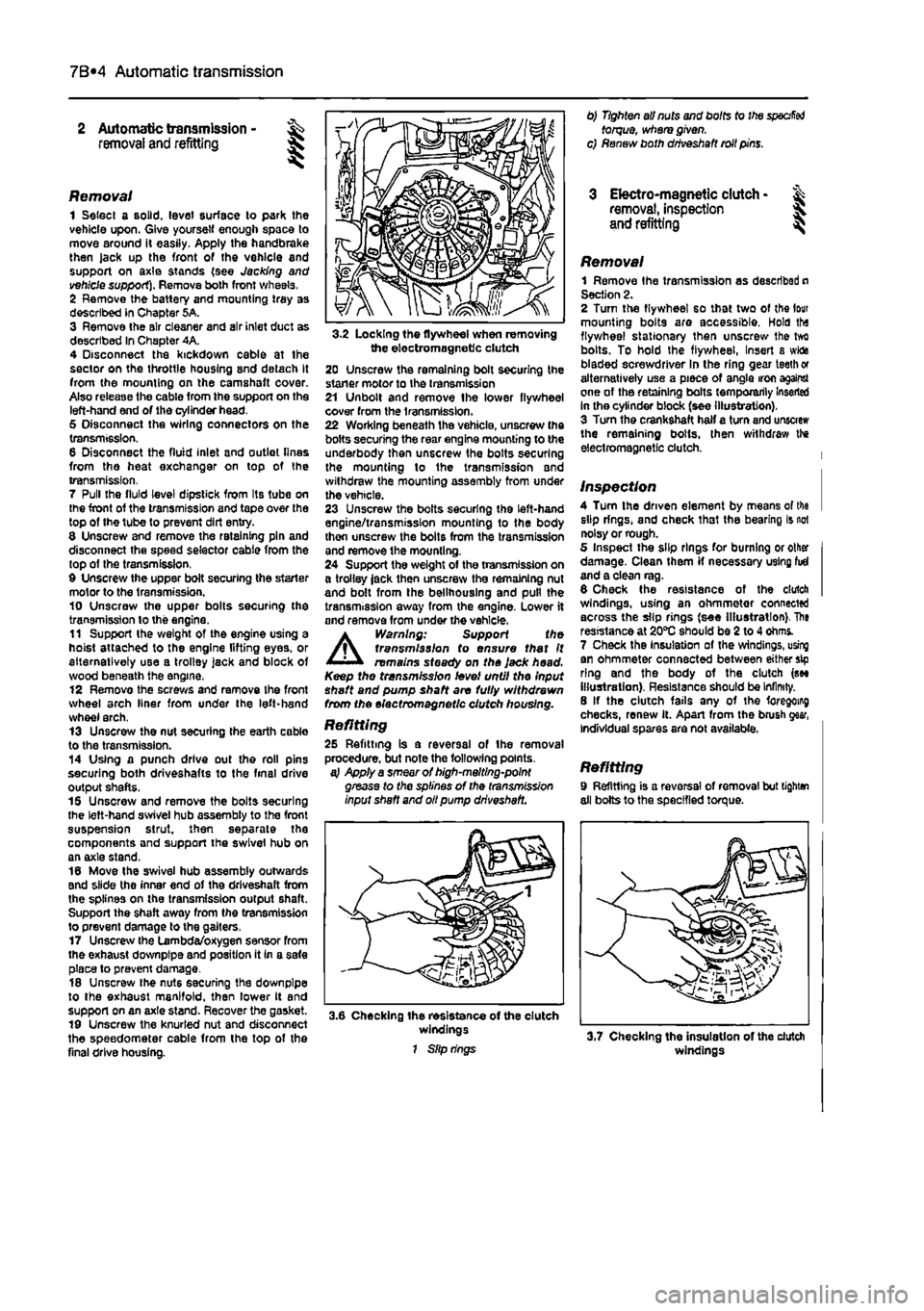
3-2 Locking the flywheel when removing the electromagnetic clutch 20 Unscrew the remaining bolt securing the staner motor to the transmission 21 Unbolt and remove Ihe lower flywheel cover from the transmission. 22 Working beneath the vehicle, unscrew the bolts securing the rear engine mounting to the underbody then unscrew the bolts securing the mounting lo the transmission and withdraw the mounting assembly from under the vehicle. 23 Unscrew the bolts securing the left-hand engine/transmission mounting to the body thon unscrew the bolts from the transmission and remove the mounting. 24 Support the weight of the transmission on a trolley jack then unscrew the remaining nut and bolt from the bellhouslng and pull the transmission away from the engine. Lower it and remove from under the vehicle.
A
Warning: Support the transmission to ensure that It remains steady on the Jack head. Keep the transmission level until the Input shaft and pump shaft are fully withdrawn from the electromagnetic clutch housing.
Refitting 25 Refitting is a reversal of the removal procedure, but note the following points. a} Apply a smear of high-melting-point grease to the splines of the transmission input shaft and oil pump driveshaft.
3.6 Checking the resistance of the clutch windings 1 Slip rings
0) Tighten all nuts and bolts to the
specified
torque, where given, c) Renew both driveshaft roll pins.
3 Electro-magnetic clutch • & removal, inspection 5. and refitting ^
Removal 1 Remove Ihe transmission as described n Section 2. 2 Turn the flywheel so that two of the lour mounting bolts are accessible, Hold tha flywheel stationary then unscrew Ihe tvrt bolts. To hold the flywheel, Insert a wida bladed screwdriver In the ring gear teeth or alternatively use a piece of angle iron against one of the retaining bolts temporarily Inserted in the cylinder block (see illustration). 3 Turn the crankshaft half a turn and unscrew the remaining bolts, then withdraw the electromagnetic clutch.
Inspection 4 Turn the driven element by means of tha slip rings, and check that the bearing is not noisy or rough. 5 Inspect the slip rings for burning or other damage. Clean them if necessary using fid and a clean rag. 6 Check the resistance of the clutch windings, using an ohmmetor connected across the slip rings (see Illustration). The resistance at 20*0 should be 2 to 4 ohms. 7 Check the Insulation of the windings, using an ohmmeter connected between either sip ring and the body of the clutch (see illustration). Resistance should be Infinity. 8 If the clutch fails any of the foregoing checks, renew it. Apart from the brush gear, Individual spares are not available.
Refitting 9 Refitting is a reversal of removal but tighten all bolts to the specified torque.
windings
Page 214 of 225
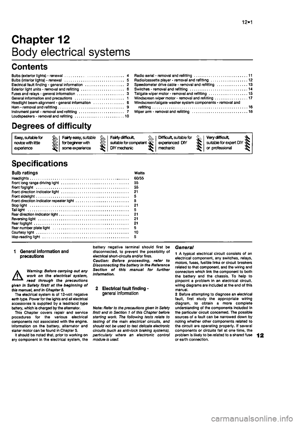
10*1
Chapter 12
Body electrical systems
Contents
Bulbs (exterior lights) - renewal 4 Bulbs (interior lights) - renewal 5 Electrical fault finding - general information 2 Exterior light units - removal and refitting 6 Fuses and relays - general Information 3 General information and precautions 1 Headlight beam alignment • general Information 6 Horn • removal and refitting 9 Instrument panel - removal and refitting 7 Loudspeakers - removal and refitting 10
Degrees of difficulty
Radio aerial - removal and refitting 11 Radio/cassette player • removal and refitting 12 Speedometer drive cable - removal and refitting 13 Switches - removal end refitting 14 Tailgate wiper motor - removal and refitting 15 Windscreen wiper motor - removal and refitting 17 Windscreen/tailgate washer system components • removal and refitting 16 Wiper arm • removal and refitting 18
Easy,
statable for ^
novice with liffle
|| experience ^
Fairly
easy,
suitable for beginner with ^ some experience ^
Fabtycffficiit,
suitable
for competent ^
DIY
mechanic ^
Difficult, suitable for
^ experienced DIY JR mechanic
Very difficult,
A,
suitable
for
expert DIY
Sj or professional ^
Specifications
Bulb ratings Watts Headlights 60/55 Front long range driving light 55 Front fogllght 55 Front direction Indicator light 21 Front sidelight 5 Front direction indicator repeater light 5 Stop light 21 Tall light 5 Rear direction indicator light 21 Reversing light 21 near fogllght 21 Hear number plate light 5 Courtesy light 10 Map reading light 5
1 Genera! information and precautions
A
Warning: fie/Ore carrying out any work on the electrical system, read through the precautions given in Safety first! at the beginning of this manual, and in Chapter 8. The electrical system is of 12-volt negative earth type. Power for the lights and all electrical accessories is supplied by a lead/acid type battery, which is charged by the alternator. This Chapter covers repair and service procedures for the various electrical components not associated with the engine. Information on the battery, alternator and starter motor can be found in Chapter 5. It should be noted that, prior to working on any component In the electrical system, the
battery negative terminal should first be disconnected, to prevent the possibility of electrical short-circuits and/or fires. Caution: Before proceeding, refer to Disconnecting the battery In the Reference Section of this manual for further information.
2 Electrical fault finding-general information
Note: Refer to the precautions given In Safety first! and in Section 1 of this Chapter before starting work. The following tests relate to testing ot the main electrical circuits, and should not be used to test delicate electronic circuits (such as antHock braking systems), particularly where an electronic con fro/ module is used.
General 1 A typical electrical circuit consists of an electrical component, any switches, relays, motors, fuses, fusible links or circuit breakers related to that component, and the wiring and connectors which link the component to both the battery and the chassis. To help to pinpoint a problem in an electrical circuit, wiring diagrams are Included at the end of this manual. 2 Before attempting to diagnose an electrical fault, first study the appropriate wiring diagram, to obtain a more complete understanding of the components included In the particular circuit concerned. The possible sources of a fault can be narrowed down by noting whether other components related to the circuit are operating properly. If several components or circuits fait at one time, the problem Is likely to be related to a shared fuse or earth connection.