Camshaft FIAT PUNTO 1995 176 / 1.G Owner's Guide
[x] Cancel search | Manufacturer: FIAT, Model Year: 1995, Model line: PUNTO, Model: FIAT PUNTO 1995 176 / 1.GPages: 225, PDF Size: 18.54 MB
Page 79 of 225
Diesel engine in-car repair procedures
2C*11
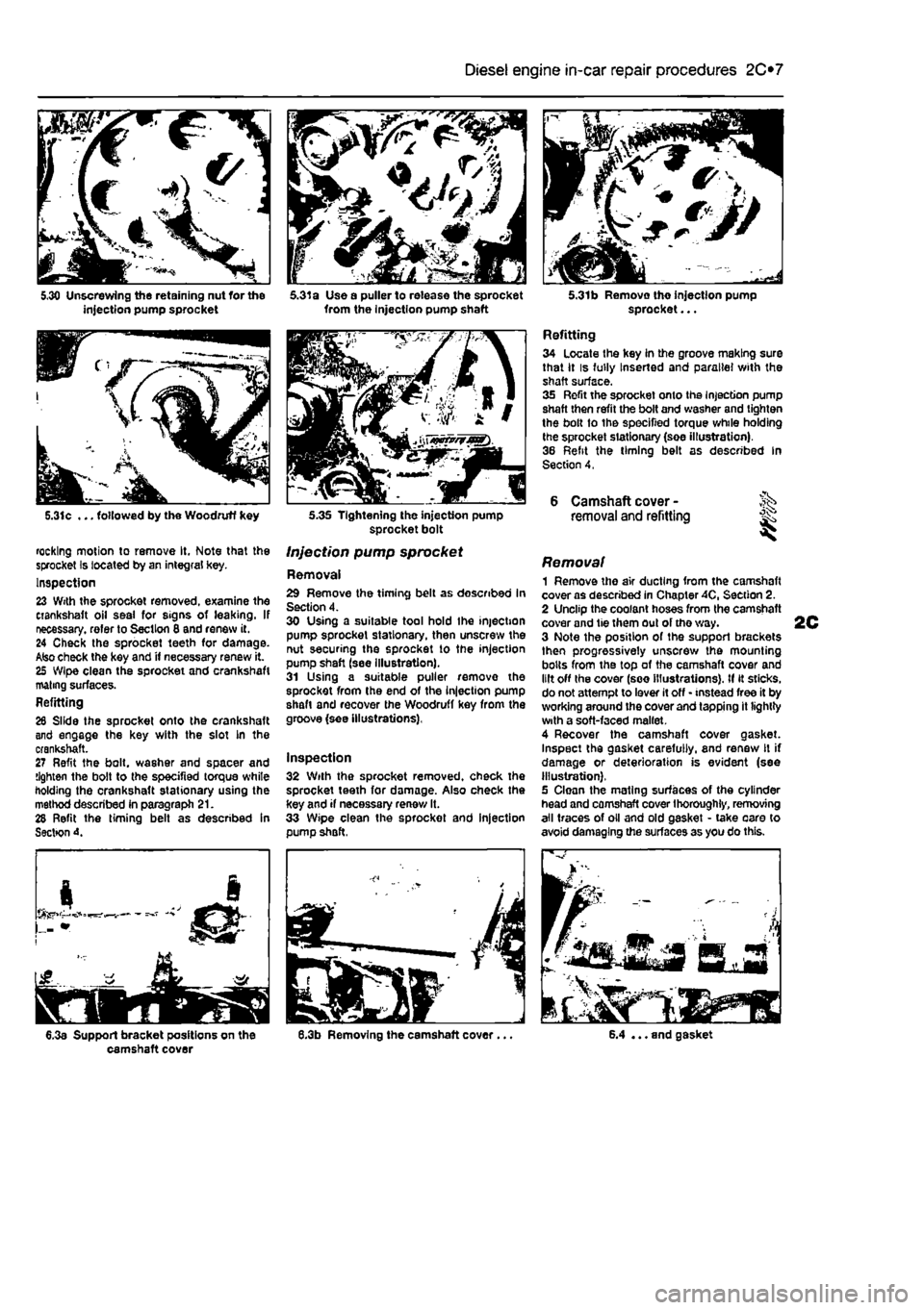
5.31c ... followed by the Woodruff key
rocking motion to remove It, Note that the sprocket Is located by an integral key. Inspection 23 With the sprocket removed, examine the crankshaft oil seal for signs of leaking. If necessary, refer to Section 8 and renew it. 24 Check the sprocket teeth for damage. Also check the key and if necessary renew it. 25 Wipe clean the sprocket and crankshaft mating surfaces. Refitting 26 Slide the sprocket onto the crankshaft and engage the key with the slot In the crankshaft. 27 Refit the bolt, washer and spacer and tighten the bolt to the specified torque white holding the crankshaft stationary using the method described in paragraph 21. 28 Refit the timing belt as described in Sectton 4.
6.3a Support bracket positions on the camshaft cover
5.31a Use a puller to release the sprocket from the injection pump shaft
5.35 Tightening the injection pump sprocket bolt
Injection pump sprocket
Removal 29 Remove the timing belt as described In Section 4. 30 Using a suitable tool hold Ihe injection pump sprocket stationary, then unscrew the nut securing the sprocket to the injection pump shaft (see illustration). 31 Using a suitable puller remove the sprocket from the end of the injection pump shaft and recover the Woodruff key from the groove (see illustrations),
Inspection 32 With the sprocket removed, check the sprocket teeth for damage. Also check the key and if necessary renew It. 33 Wipe clean the sprocket and injection pump shaft,
5.31b Removo tho injection pump sprocket...
Refitting 34 Locate the key in the groove making sure that it is fully Inserted and parallel with the shaft surface. 35 Refit the sprocket onto the Injection pump shaft then refit the bolt and washer and tighten the bolt to the specified torque while holding the sprocket stationary (soe illustration). 36 Refit the timing belt as described In Section 4,
6 Camshaft cover -removal and refitting ^
Removal 1 Remove the air ducting from the camshaft cover as described in Chapter 40, Section 2. 2 Unclip the coolant hoses from the camshaft cover and tie them out of tho way. 3 Note the position of the support brackets then progressively unscrew the mounting bolts from the top of the camshaft cover and lilt off the cover (see illustrations). If it sticks, do not attempt to lever it off • instead free it by working around the cover and tapping it lightly with a soft-faced mallet. 4 Recover the camshaft cover gasket. Inspect the gasket carefully, and renew It if damage or deterioration is evident (see illustration). 5 Clean the mating surfaces of the cylinder head and camshaft cover thoroughly, removing all traces of oil and old gasket • take oaro to avoid damaging the surfaces as you do this.
6.4 ... and gasket
Page 80 of 225
2C*2 Diesel engine in-car repair procedures
Refitting 6 Locate a new gasket on the cylinder head and make sure tt Is correctly seated. 7 Lower the cover onto the gasket making sure the gasket Is not displaced, 8 Insert the mounting bolts and tighten them securely In a progressive sequence. Position Ihe support brackets as noted during removal. 9 Clip ihe coolant hoses in position then refil the air ducting.
7 Camshaft oil seal -renewal
8 Crankshaft oil seals -renswal I
9 Cylinder head -
removal
and refitting
1 Remove the timing belt and camshaft sprocket as descnbed in Sections 4 and 5. 2 Using a suitable hooked instrument, remove tho oil seal from the cylinder head taking care nol to damage the surface of the camshafl. Alternatively drill a small hole In tho oil seal and Insert a self-topping screw - the seal can then be removed by pulling on the screw with a pair of pliers. 3 Clean the seating In the cylinder head and tho end of the camshaft To prevent damage to the new oil seal as It is being fitted, wrap some adhesive tape around the end ol the camshaft and lightJy oil it. 4 Dip tho new ail s«al In oil then locate it over Ihe camshaft making sure that the sealing lips are facing inwards. 5 Using a suitable tubular drift, drive the oil seal squarely into the cylinder h*ad. Remove the adhesive tap© 6 Refit the camshaft sprocket and timing belt with reference to Sections 6 and 4.
Front (right-hand side) oil seal t The front oil seal is located in the oil pump casing on the front of the crankshaft. Remove the timing belt as described in Section 4 and the crankshaft sprocket as described in Section 5, 2 Using a suitable hooked instrument, remove the oil seal from the oil pump casing taking care not to damage the surface of the crankshaft. Alternatively drill a small hole In the oil soal and insert a self-tapping screw - the seal can then be removed by pulling on the screw with a pair of pliers. 3 Clean the seating in the oH pump and the surface of the crankshaft. To prevent damage to the new off seal as It Is being fitted, wrap some adhesive tape around the end of tha crankshaft and lightly oil it. 4 Oip the new oii seal In oil then otter it up to the oil pump casing making sure that the sealing Hps are facing inwards,
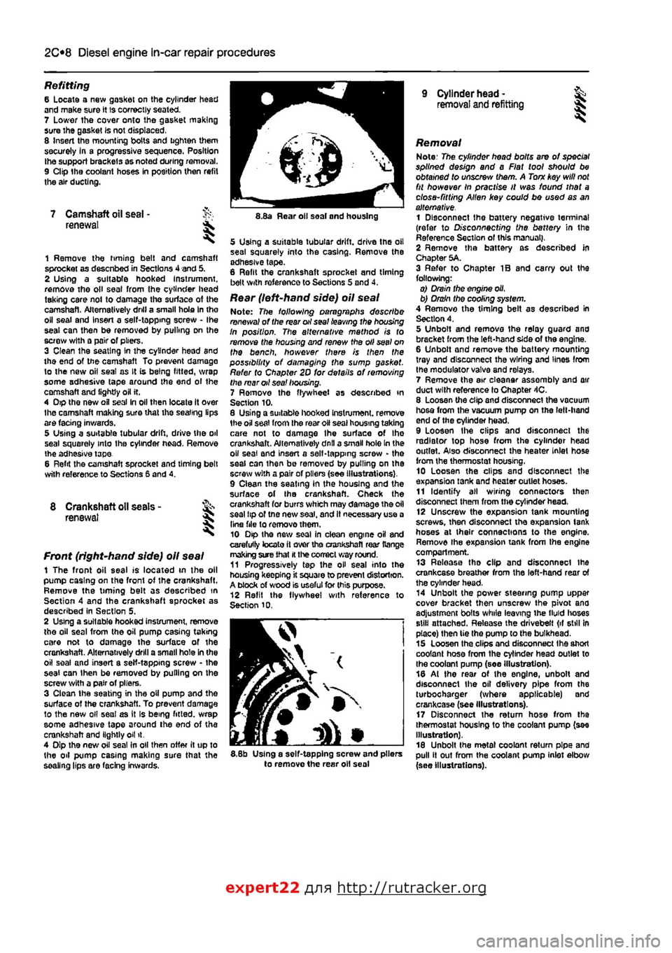
8.Ba Rear oil soal and housing
5 Using a suitable tubular drift, driva the oil sea! squarely into the casing. Remove the adhesive tape. 6 Refit the crankshaft sprocket and timing belt with reference to Sections 5 and 4.
Rear (left-hand side) oil seal Note: The following paragraphs describe renewal of the rear oil seal leaving the housing In position. The alternative mathod is to remove the housing and renew the oil seel on the bench, however there is then the possibility of damaging the sump gasket. Refer to Chapter 2D for details of removing the mar oil sea! housing. 7 Ramove the flywheel as described in Section 10. 8 Using a suitable hooked Instrument. remove 1he oil seat from the roar oil seal housing taking care not to damage Ihe surface of Ihe crankshaft. Alternatively dnll a small hole In the o» seal and insert a self-tapping screw - the seal can ihan be removed by pulling on the screw with a pair of pliers (see Illustrations), 9 Clean the seating in the housing and the surface of the crankshaft. Check the crankshaft for burrs which may damage the oil seal tip of tno new saal, and It necessary use a Una file to removothem. 10 Dip the new soal in clean engine oil and carefully tocato it over tho crankshafl rear Range making sure that
H
the correct way round. 11 Progressively tap the oH seal into the housing keepfng it square to prevent distortion. A block of wood is useful for this purpose. 12 Refit the flywheel with reference to Section 10.
I
5.8b Using a self-tapping screw and pliers to remove the rear oil seal
Removal Note: The cylinder head bolts are of special splined design and a Fiat tool should be obtained to unscrew them. A Torn key will
not
fit however In practise It was found that a close-fitting Allen key could bo used as an alternative. 1 Disconnect the battery negative terminal (refer to Disconnecting the battery in the Reference Section of this manual), 2 Remove tha battery as described In Chapter 5A. 3 Refer to Chapter IB and carry out the following: o) Drain the engine oil, b) Drain the cooling system. 4 Remove the timing belt as described in Section 4. 5 Unbolt and remova the relay guard and bracket from the left-hand side of the engine. 6 Unbolt and remove the battery mounting tray and disconnect the wiring and lines from the modulator valva and relays. 7 Remove the air eleanar assembly and air duct with reference lo Chapter 4C. 8 Loosen the clip and disconnect the vacuum hosa from the vacuum pump on the left-hand end of the cylinder head. 9 Loosen Ihe clips and disconnect the radiator top hose from the cylinder head outlet. Also disconnect the heater inlet hose from the thermostat housing, 10 Loosen the clips and disconnect the expansion tank and heater outlet hoses. 11 Identify all wiring connectors then disconnect them from the cylinder head, 12 Unscrew the expansion tank mounting screws, then disconnect tha expansion tank hoses at their connections to the engine. Remove the expansion tank from tha engine compartment. 13 Release tha clip and disconnect ihe crankcase breather from the left-hand rear of the cylinder head. 14 Unbolt the power steering pump uppar cover bracket then unscrew the pivot ana adjustment bolts while leaving ihe tMd lioses still attached. Release the drivebelt (if still In place) then tie the pump to the bulkhead. 15 Loosen tha clips and disconnect Ihe short coolant hose from the cylinder head outlet to the coolant pump (soe illustration). 18 At the rear of the engine, unbolt and disconnect the oil delivery pipe from the turbocharger (where applicable) and crankcase (see Illustrations). 17 Disconnect the return hose from tha thermostat housing to the coolant pump (see Illustration), 18 Unbolt the metal coolant return pipe and pull it out from the coolant pump inlet elbow (see Illustrations).
expert22 flna http://rutracker.org
Page 81 of 225
Diesel engine in-car repair procedures
2C*11
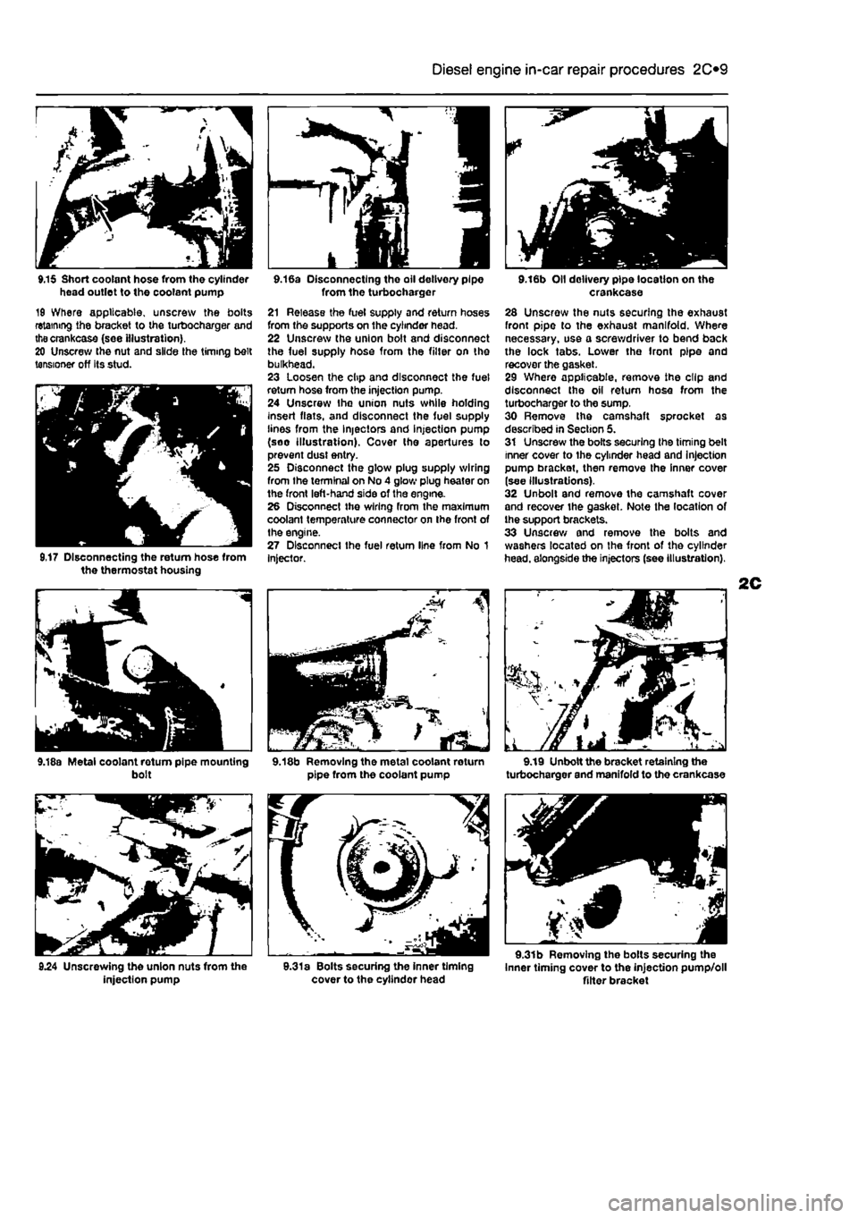
9.15 Short coolant hose from the cylinder head outlet to the coolant pump 19 Where applicable, unscrew the bolts retaining the bracket to the turbocharger and thecrankcase (see illustration). 20 Unscrew the nut and slide the timing belt tensioner off Its stud.
9,17 Disconnecting the return hose from the thermostat housing
9.18a Metal coolant rotum pipe mounting bolt
injection pump
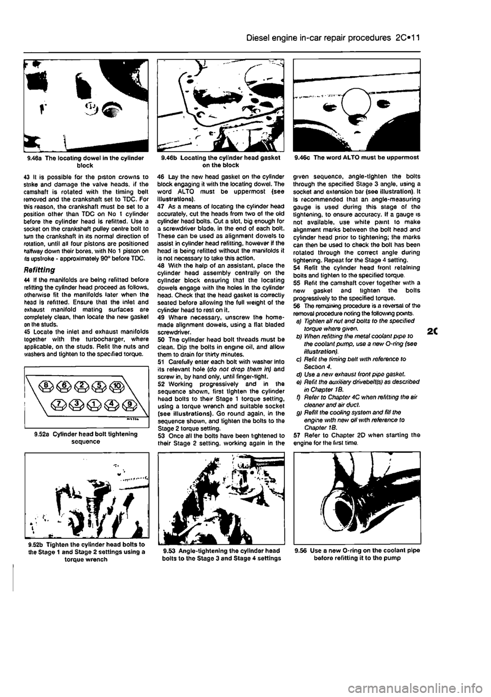
9.16a Disconnecting the oil delivery pipe from the turbocharger 21 Release the fuel supply and return hoses from the supports on the cylinder head. 22 Unscrew the union bolt and disconnect the fuel supply hose from the filter on the bulkhead. 23 Loosen the clip and disconnect the fuel return hose from the injection pump. 24 Unscrew Ihe union nuts while holding insert fiats, and disconnect the fuel supply lines from the Injectors and injection pump (soo illustration). Cover tho apertures to prevent dust entry. 25 Disconnect the glow plug supply wiring from the terminal on No 4 glow plug heater on the front left-hand side of the engine. 26 Disconnect the wiring from the maximum coolant temperature connector on the front of the engine. 27 Disconnect the fuel return line from No 1 Injector.
9.18b Removing the metal coolant return pipe from the coolant pump
9.31a Bolts securing the inner timing cover to the cyllndor head
9.16b Oil delivery pipe location on the crankcase 28 Unscrew the nuts securing the exhaust front pipe to the exhaust manifold. Where necessary, use a screwdriver to bend back the lock tabs. Lower the front pipe and recover the gasket. 29 Where applicable, remove the clip and disconnect the oil return hose from the turbocharger to the sump. 30 Remove the camshaft sprocket as described in Section 5. 31 Unscrew the bolts securing the timing belt inner cover to the cylinder head and injection pump bracket, then remove the inner cover (see illustrations). 32 Unbolt and remove the camshaft cover and recover the gasket. Note the location of the support brackets. 33 Unscrew and remove the bolts and washers located on the front of the cylinder head, alongside the injectors (see illustration),
9.19 Unbolt the bracket retaining the turbocharger and manifold to the crankcase
9.31b Removing the bolts securing the Inner timing cover to the injection pump/oll Alter bracket
Page 82 of 225
2C*2 Diesel engine in-car repair procedures
9.31c Removing the inner timing cover
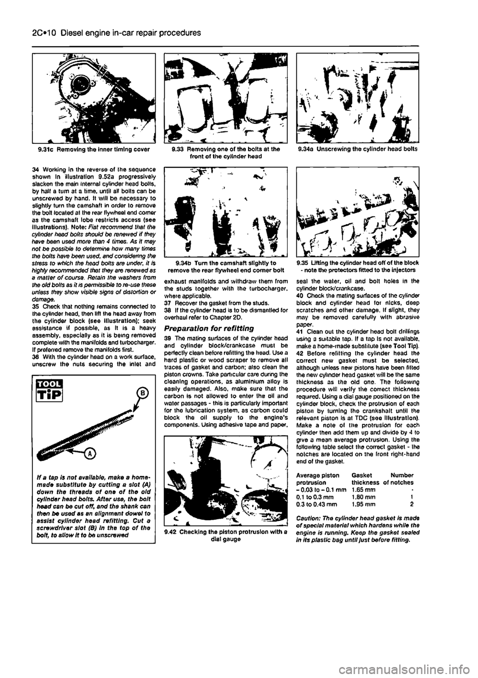
34 Working in ihe reverse of Ihe sequence shown In illustration 9.52a progressively slacken the main Internal cylinder head bolts, by halt a turn at a time, until all bolts can be unscrewed by hand. It will be necessary to slightly turn the camshaft in order to remove the bolt located at the rear llywheel end comer as the camshaft lobe restricts access (see illustrations). Note: Fiat recommend that the cylinder head boils should be renewed if they have been used more than 4 times. As It may not be possible to determine how many times the bolts have been used. end considering the stress to which the head bolts are under, it is highly recommended that they are renewed as a matter of course. Retain ihe washers from the old bolts as it is permissible to re-use these unless they show visible signs of distortion or damage. 35 Check that nothing remains connected to the cylinder head, then lift the head away from the cylinder block (see Illustration); seek assistance if possible, as It is a heavy assembly, especially as it is being removed complete with the manifolds and turbochargar. If preferred remove the manifolds first. 36 With the cylinder head on a work surface, unscrew the nuts securing the inlet and
3.33 Removing one of the bolts at the front of the cylinder head 9.34a Unscrewing the cylinder head bolts
ff a tapis not available, make a home-made substitute by cutting a slot (A) down the threads of one of the old cylinder head bolts. After use, the bolt head can be cut off, and the shank can then be used as an alignment dowel to assist cylinder head refitting. Cut a screwdriver slot (B) In the top of the bolt, to allow it to be unscrewed
9.34b Turn the camshaft slightly to remove the rear flywheel end comer boit exhaust manifolds and withdraw them from the studs together with the turbocharger. where applicable. 37 Recover the gasket from the studs. 38 If the cylinder head is to be dismantled for overhaul refer to Chapter 2D. Preparation for refitting 39 The mating surfaces of the cylinder head and cylinder block/crankcase must be perfectly clean before refitting the head. Use a hard plastic or wood scraper to remove all traces of gasket and carbon; also dean the piston crowns, Take particular care during the cleaning operations, as aluminium alloy is easily damaged. Also, make sure that the carbon is not allowed to enter the oil and water passages - this is particularly important for the lubrication system, as carbon could block the oil supply to the engine's components. Using adhesive tape and paper.
9.42 Checking the piston protrusion with a dial gauge
9.35 Lifting the cylinder head off of the block - note the protectors fitted to the injectors seal the water, oil and bolt holes In the cylinder block/crankcase. 40 Check the mating surfaces of the cylinder block and cylinder head for nicks, deep scratches and other damage. If slight, (hey may be removed carefully with abrasive paper, 41 Clean out the cylinder head bolt drillings using a suitable tap, If a tap Is not available, make a home-made substitute (see Tool Tip). 42 Before refitting the cylinder head th* correct new gasket must be selected, although unless new pistons have been fitted the new cylinder head gasket will be the same thickness as the old one. The following procedure will verify the correct thickness required. Using a dial gauge positioned on the cylinder block, check the protrusion of each piston by turning the crankshalt until the relevant piston Is at TDC (see Illustration). Make a note of the protrusion for oach cylinder then add them up and divide by 4 to give a mean average protrusion, Using the following table select the correct gasket - Ihe notcnes are located on the Iront right-hand end of (he gasket.
Average piston Gasket Number protrusion thickness of notches -0.03 to -0.1 mm 1.65 mm
0.1
to 0.3 mm 1.80 mm 1 0.3 to 0.43 mm 1.95 mm 2
Caution: The cylinder head gasket Is made of special material which hardens while the engine is running. Keep the gasket sealed in Its plastic bag until Just before fitting.
Page 83 of 225
Diesel engine in-car repair procedures 2C*11
r
<3^
9.46a The locating dowel in the cylinder block 43 It is possible for the ptston crowns to stnke and damage the valve heads, if the camshaft is rotated v/ith the timing belt removed and the crankshaft set to TDC. For this reason, the crankshaft must be set to a position other than TDC on No t cylinder before the cylinder head is refitted. Use a socket on the crankshaft pulley centre bolt to turn the crankshaft in its normal direction of rotation, until all four pistons are positioned Halfway down their bores, v/ith No 1 piston on lis upstroke - approximately 90° before TDC.
Refitting 44 If the manifolds are being refitted before refitting the cylinder head proceed as follows, otherwise fit the manifolds later when the head is refitted. Ensure thai the inlet and exhaust manifold mating surfaces are completely clean, then locale the new gasket on the studs. 45 Locate the inlet and exhaust manifolds together with the turbocharger, where applicable, on the studs. Refit the nuts and washers and tighten to the specified torque.
sequence
f^/f
9.52b Tighten the cylinder head bolts to the Stage 1 and Stage 2 settings using a torque wrench
on the block 46 Lay the new head gasket on the cylinder block engaging it with the locating dowel. The word ALTO must be uppermost (see illustrations). 47 As a means of locating Ihe cylinder head accurately, cut the heads from two of the old cylinder head bolts. Cut a slot, big enough for a screwdriver blade, in the end of each bolt. These can be used as alignment dowels to assist in cylinder head refitting, however If the head is being refitted without the manifolds it is not necessary to take this action. 48 With the help of an assistant, place the cylinder head assembly centrally on the cylinder block ensuring thai the locating dowels engage with Ihe holes in the cylinder head. Check that the head gasket Is correctly seatod before allowing the full weight of the cylinder head to rest on it. 49 Where necessary, unscrew the home-made alignment dowels, using a flat bladed screwdriver. 50 The oyllnder head bolt threads must be clean. Dip the bolts in engine oil. and allow them to drain for thirty minutes. 51 Carefully enter each bolt with washer into its relevant hole (do not drop them in) and screw in, by hand only, until finger-tight. 52 Working progressively and In the sequence shown, first tighten the cylinder head bolts to their Stage 1 torque setting, using a torque wrench and suitable socket (see illustrations). Go round again, in the sequence shown, and tighten the bolls to the Stage 2 torque setting. 53 Once all the bolts have been tightened to their Stage 2 setting, working again in the
bolts to the Stage 3 and Stage 4 settings
9.46c The word ALTO must be uppermost
given sequence, angle-tighten the bolts through the specified Stage 3 angle, using a socket and extension bar (see illustration). It Is recommended that an angle-measuring gauge is used during this stage of the tightening, to ensure accuracy. If a gauge is not available, use white paint to make alignment marks between the bolt head and cylinder head prior to tightening; the marks can then be used to check tho bolt has been rotated through the correct angle during tightening. Repeat for the Stage 4 setting. 54 Refit the cylinder head front retaining bolts and tighten lo the specified torque. 55 Refit the camshaft cover together with a new gasket and tighten the bolts progressively to the specified torque. 56 The remaining procedure is a reversal of the removal procedure noting the following points. a) Tighten all nut and bolts to the specified torque where given. b) When refitting the metal coolant pipe to the coolant pump, use a new O-ring (see illustration). cj Refit the timing belt with reference to Section 4. d) Use a new exhaust front pipe gasket. e) Refit the auxiliary dhvebeltfs) as described in Chapter 1B. f) Refer to Chapter 4C when refitting the
air
cleaner and air duct. g) Refill the cooling system and fill the engine with new oil with reference to Chapter 1B. 57 Refer to Chapter 20 when starting the engine for the first time.
9.56 Use a new O-ring on the coolant pipe before refitting it to the pump
Page 88 of 225
2D»1
Chapter 2 Part D:
Engine removal and overhaul procedures
Contents
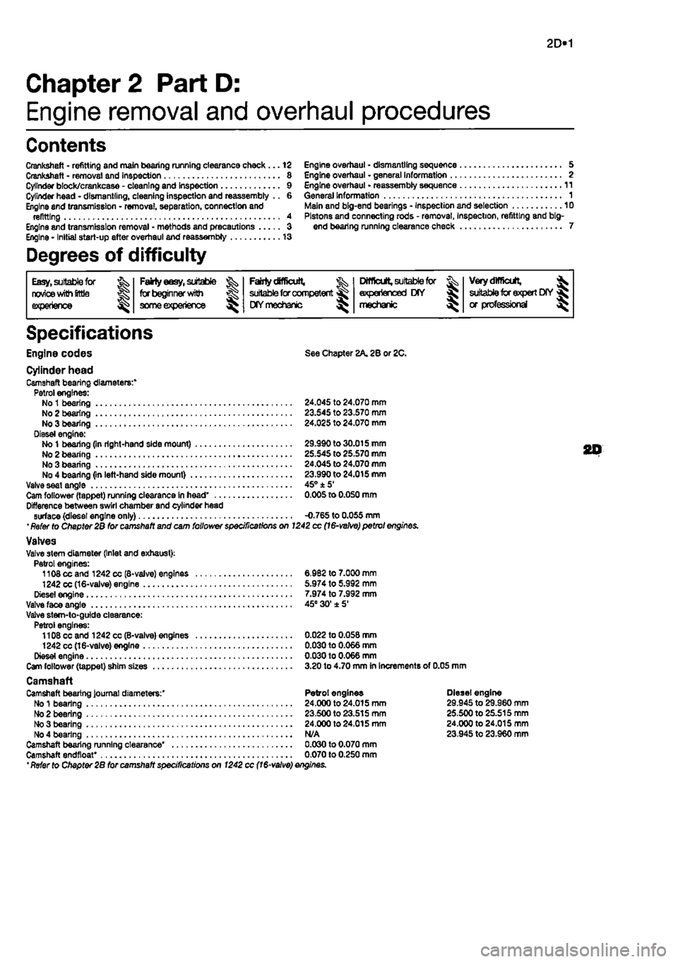
Crankshaft - refitting and main bearing running clearance check... 12 Engine overhaul • dismantling sequence 5 Crankshaft • removal and inspection 8 Engine overhaul • general Information .. Cylinder block/crankcase - cleaning and Inspection 9 Engine overhaul - reassembly sequence Cylinder head - dismantling, cleaning inspection and reassembly .. 6 General Information Engine and transmission - removal, separation, connection and refitting 4 Engine and transmission removal • methods and precautions 3 Engine * Initial start-up after overhaul and reassembly 13
Degrees of difficulty
Engine overhaul - general Information 2 11 1 Main and big-end bearings - Inspection and selection 10 Pistons and connecting rods - removal, inspection, refitting and big-end bearing running clearance check 7
Easy, suftable for FaHy easy, suitable ^ FaMy difficult, ^ Difficult, suitable for % Very difficult, ^ novice with littla | for beginner with suitable for competent ^ experienced DIY suitable for expert DIY « experience | some experience ^ HYmechanic mechanic or professional ^
Specifications
Engine codes See Chapter 2A. 2B or ZC.
Cylinder head Camshaft bearing diameters:* Petrol engines: No
1
bearing 24.045 to 24.070 mm No 2 bearing 23.S45 to 23.570 mm No 3 bearing 24.025 to 24.070 mm Diesel engine: No
1
bearing (In right-hand side mount) 29.990to30.015mm No 2 bearing 25.545 to 25.570 mm No 3 bearing 24.045 to 24.070 mm No 4 bearing (in left-hand side mount) 23.990 to 24.015 mm Valve seat angle 45° ±5' Cam follower (tappet) running clearance In head' 0.005 to 0.050 mm Difference between swirl chamber and cylinder head surface (diesel engine only) -0.765 to 0.055 mm '
Refer
to Chapter 2B for camshaft and cam follower specifications on 1242 cc
(16-velve)
petrol engines. Valves Valve stem diameter (Inlet and exhaust): Petrol engines: 1108 cc and 1242 cc (8-valve) engines 6.982 to 7.000 mm 1242
CC
(16-valve) engine 5.974 to 5.992 mm Diesel engine 7.974 to 7.992 mm Valve face angle 45° 30'±5' Valve stem-to-guide clearance: Petrol engines: 1108 cc and 1242 cc(B-valve) engines 0.022 to 0.05B mm 1242 cc (16-valve) engine 0.030 to 0.066 mm Diesel engine 0.030 to 0.066 mm Cam follower (tappet) sJiim sizes 3.20 to 4.70 mm In Increments of 0.05 mm Camshaft Camshaft bearing Journal diameters:' Petrol engines Diesel engine No
1
bearing 24.000 to 24.015 mm 29.945 to 29.960 mm No 2 bearing 23.500 to 23.515 mm 25.500 to 25.515 mm No 3 bearing 24.000 to 24.015 mm 24.000 to 24.015 mm No 4 bearing N/A 23.945 to 23.960 mm Camshaft bearing running clearance* 0.030 to 0.070 mm Camshaft endfloat* 0.070 to 0.250 mm 'Refer to Chapter 2B for camshaft specifications on 1242 cc
(16-valve)
enginss.
20
Page 90 of 225
2D*10 Engine removal and overhaul procedures
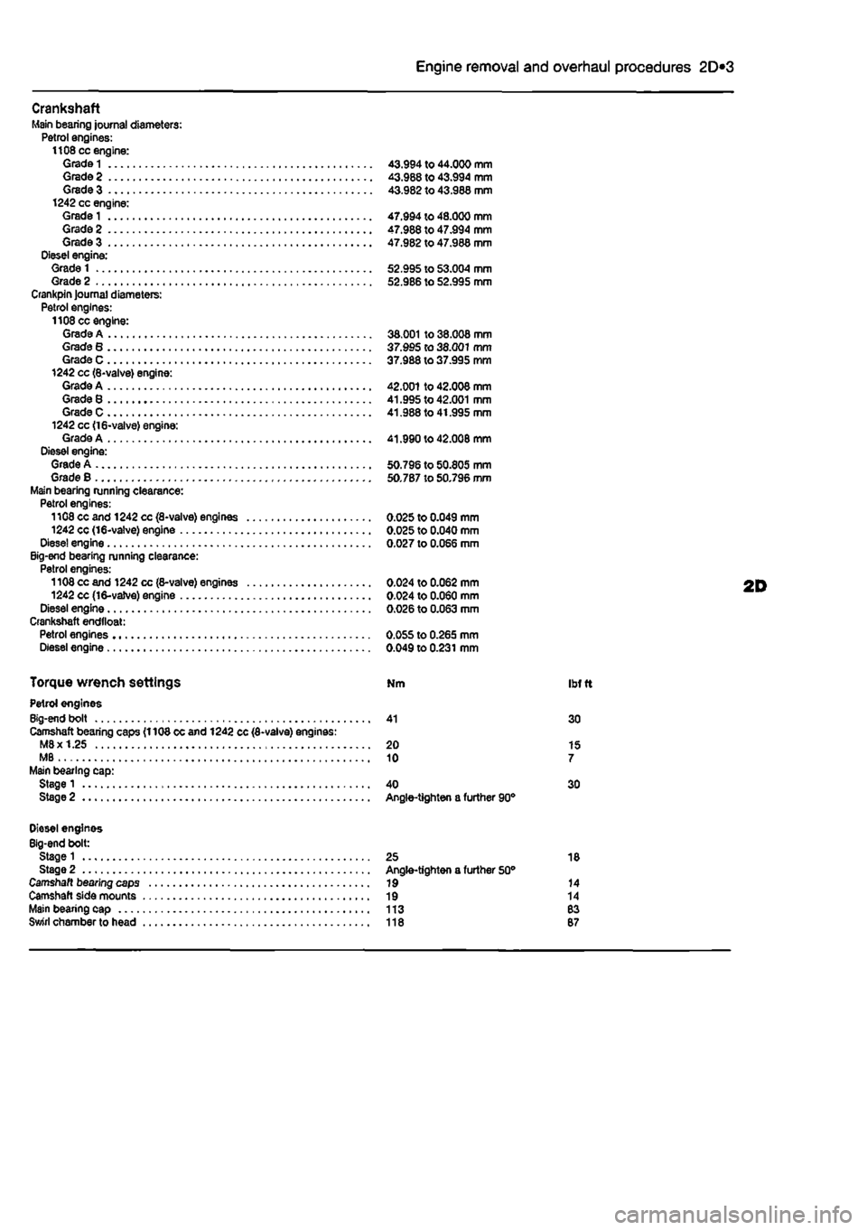
Crankshaft Main bearing journal diameters: Petrol engines: 1108 cc engine: Grade
1
43.994 to 44.000 mm Grade 2 43.988 to 43.994 mm Grade 3 43.982 to 43.988 mm 1242 cc engine: Grade
1
47.994 to 48.000 mm Grade 2 47.988 to 47.994 mm Grade 3 47.982 to 47.988 mm Diesel engine: Grade 1 52.995 to 53.004 mm Grade 2 52.986 to 52.995 mm Crankpin Journal diameters: Petrol engines: 1108 cc engine: Grade A 38.001 to 38.008 mm Grade 8 37.995 to 38.001 mm Grade C 37.988 to 37.995 mm 1242 cc (8-valve) engine: Grade A 42.001 to 42.008 mm Grade 8 41.995 to 42.001 mm Grade C 41.988 to 41.995 mm 1242 cc <16-valve) engine: Grade A 41.990 to 42.008 mm Diesel engine: Grade A 50.796 to 50.805 mm Grade B 50.787 to 50.796 mm Main bearing running clearance: Petrol engines: 1108 cc and 1242 cc (8-valve) engines 0.025 to 0.049 mm 1242 cc (16-valve) engine 0.025 to 0.040 mm Dlese! engine 0.027 to 0.066 mm Big-end bearing running clearance: Petrol engines: 1108 cc and 1242 cc (8-valve) engines 0.024 to 0.062 mm 1242 cc (16-vaJve) engine 0.024 to 0.060 mm Diesel engine 0.026 to 0.063 mm Crankshaft endtloat: Petrol engines 0.055 to 0.265 mm Diesel engine 0.049 to 0.231 mm
Torque wrench settings Nm ibf
t
Petrol engines Big-end bolt 41 30 Camshaft bearing caps (1108 cc and 1242 cc (8-valve) engines: M8x 1.25 20 15 MB 10 7 Main bearing cap: Stage 1 40 30 Stage 2 Angle-tighten a further 90°
Diesel engines Big-end bolt: Stage 1 25 18 Stage 2 Angle-tighten a further 50° Camshaft bearing caps 19 14 Camshaft side mounts 19 14 Main bearing cap 113 83 Swirl chamber to head 118 87
Page 99 of 225
2D*10 Engine removal and overhaul procedures
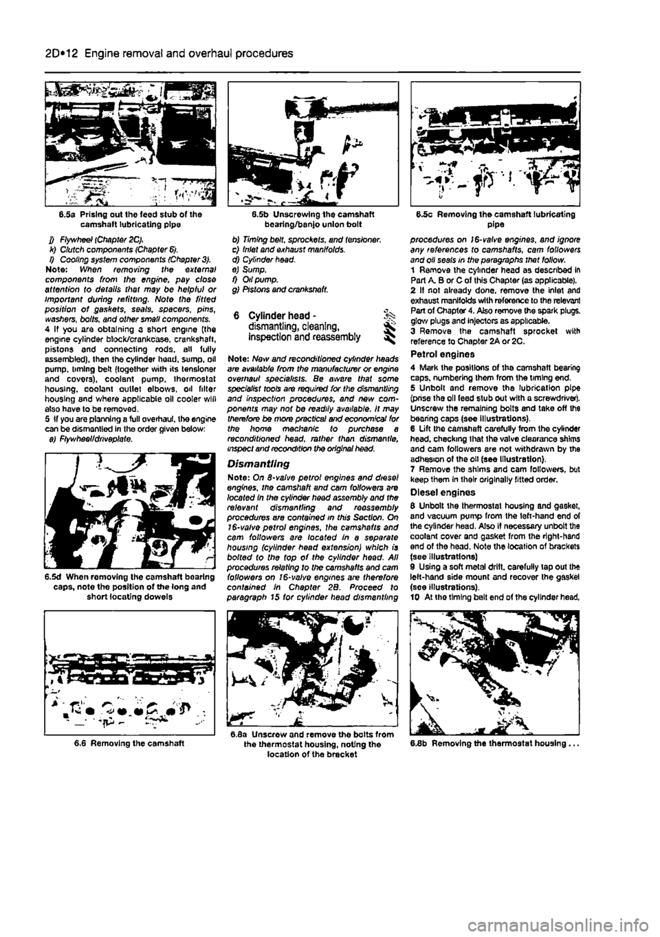
6.5s Prising out the feed stub of the camshaft lubricating pipe J) Flywheel (Chapter 2C). k) Clutch components (Chapter
6).
I) Cooling system components (Chapter
3).
Note: When removing trie external components from the engine, pay close attention to details that may be helpful or important during refitting. Note the fitted position of gaskets, seals, spacers, pins, washers, bolts, and other small components. 4 If you are obtaining a short engine (the engine cylinder block/crankcase, crankshaft, pistons and connecting rods, all fully assembled), then the cylinder head, sump, oil pump, timing belt (together with its tensloner and covers), coolant pump, thermostat housing, coolant outlet elbows, oil filter housing and where applicable oil cooler will also have to be removed. 5 If you are planning a full overhaul, the engine can be dismantled in the order given below: $) Ftywhaoi/drivoplate.
6.5d When removing the camshaft bearing caps, note the position of the (ong and short locating dowels
bearing/banjo union bolt b) Timing belt, sprockets, and tensioner. c) Inlet and exhaust manifolds. d) Cylinder head. e) Sump. f) Oil pump. g) Pistons and crankshaft.
6 Cylinder head - % dismantling, cleaning, inspection and reassembly ^
Note: Now and reconditioned cylinder heads are available from the manufacturer or engine overhaul specialists. Be aware that some specialist tools are required for the dismantling and inspection procedures, and new com-ponents may not be readily available. It may therefore be mors practical and economical for the home mechanic to purchase a reconditioned head, rather than dismantle, inspect and recondition the original head.
Dismantling Note: On 8-valve petrol engines and diesel engines, the camshaft and cam followers are /oca fed In the cylinder head assembly and the relevant dismantling and reassembly procedures are contained in this Section. On 1$-valve petrol engines, the camshafts and cam followers are /oca fed In a separate housing (cylinder head extension) which is bo/fed fo the top of the cylinder head. All procedures relating to the camshafts and cam followers on 16-valve engines are therefore contained in Chapter 2B. Proceed fo paragraph 15 for cylinder head dismantling
6.8a Unscrew and remove the bolts from the thermostat housing, noting the location of the bracket
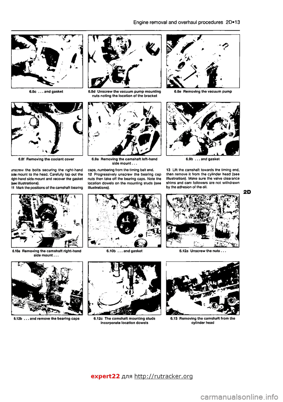
6.5c Removing the camshaft lubricating pipe procedures on /6-vafve engines, and ignore any references to camshafts, cam followers and oil seals in the paragraphs that follow. 1 Remove the cylinder head as described in Part A. B or C of this Chapter (as applicable). 2 If not already done, remove the inlet and exhaust manifolds with reference to the relevant Part of Chapter 4. Also remove the spark plugs, glow plugs and injectors as applicable. 3 Remove the camshaft sprocket with reference to Chapter 2A or 2C. Petrol engines 4 Mark the positions of the camshaft bearing caps, numbering them from the timing end. 5 Unbolt and remove the lubrication pipe (prise the oil feed stub out with a screwdriver). Unscrew the remaining bolts and take off the bearing caps (see illustrations). 6 Lift the camshaft carefully from the cylinder head, checking lhat the valve clearance shims and cam followers are not withdrawn by the adhesion of the oil (see Illustration). 7 Remove the shims and cam followers, but keep them In their originally fitted order. Diesel engines 8 Unbolt the thermostat housing and gasket, and vacuum pump from the left-hand end of the cylinder head. Also if necessary unbolt the coolant cover and gasket from the right-hand end of the head. Note the location of brackets (see illustrations) 9 Using a soft metal drift, carefully lap out the left-hand side mount and recover the gasket (soe illustrations). 10 At tho timing bait end of the cylinder head.
6.8b Removing the thermostat housing ... 6.6 Removing the camshaft
Page 100 of 225
2D*10 Engine removal and overhaul procedures
V.
^
•
• - >v
4L
6.8c ... and gasket
unscrew the bolts securing the right-hand Side mount to the head. Carefully tap out the right-hand side mount and recover the gasket (see illustrations). 11 Mark the positions of the camshaft bearing
6.10a Removing tho camshaft right-hand side mount...
6.12b ... and remove the bearing caps
6.8d Unscrew the vacuum pump mounting nuts noting the location of the bracket
caps, numbering from the timing belt end. 12 Progressively unscrew the bearing cap nuts then take off the bearing caps. Note the location dowels on the mounting studs (sae Illustrations).
6.12c The camshaft mounting studs incorporate location dowels
6.8e Removing the vacuum pump
13 Lift the camshaft towards the timing end. then remove it from the cylinder head (see illustration). Make sure the valve clearance shims and cam followers are not withdrawn by the adhesion of the oil.
6.13 Removing the camshaft from the cylinder head
expert22 fl/in http://rutracker.org
Page 102 of 225
2D*10 Engine removal and overhaul procedures
6.25 Checking the cylinder head for distortion 6.27 Checking the valve guides and valves for wear B.29a Diesel swirl chamber protrusion can be checked using a dial gauge...
scrape off the majority of the deposits with a blunt biade first, then use the wire brush. Caution: Do not erode the sealing surface ot the valve face. 23 Thoroughly clean the remainder of the components using solvent and allow them to dry completely. On 6-valve petrol and diesel engines, discard the oil seals, as new items must be fitted when the cylinder head is reassembled.
Inspection
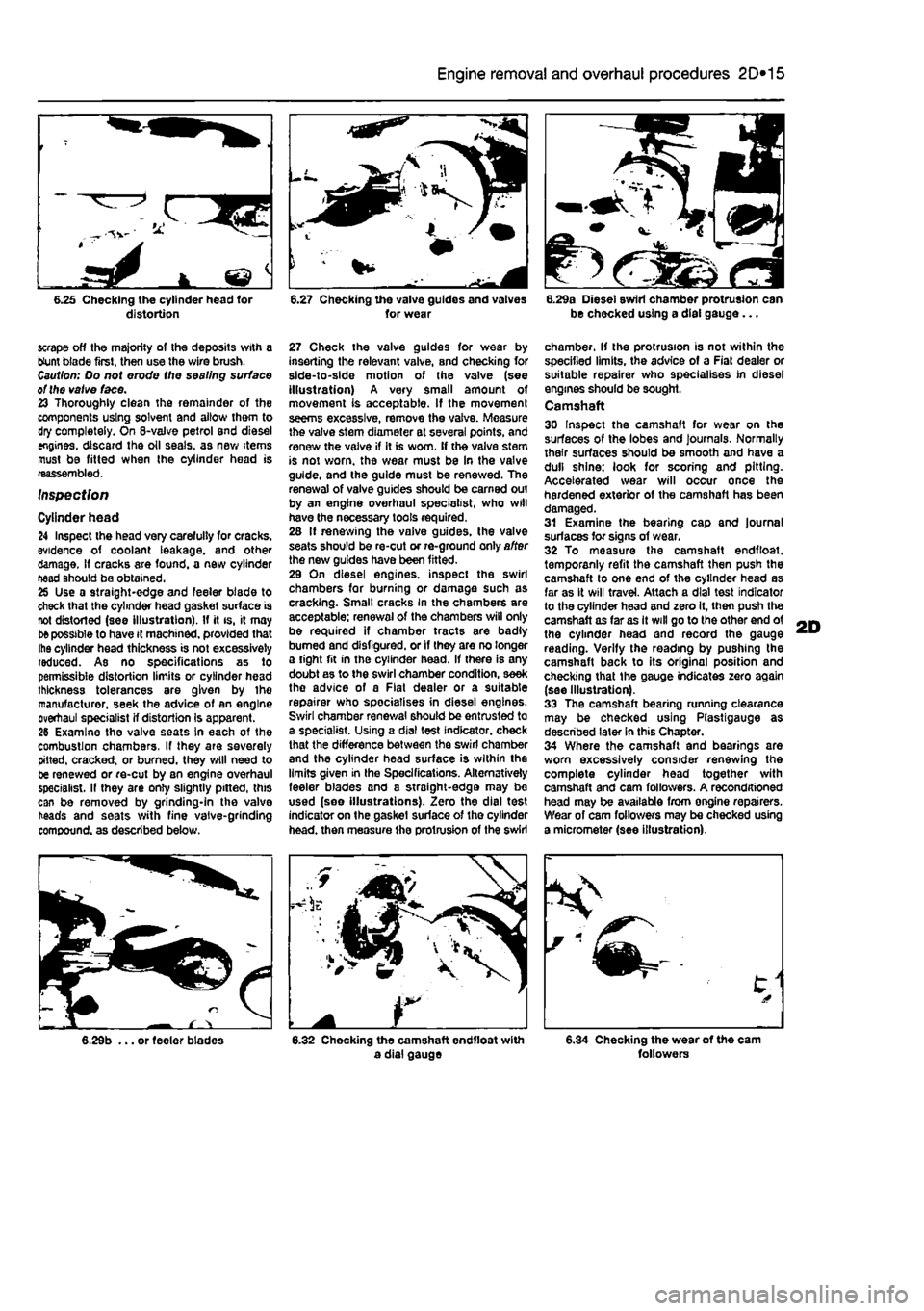
Cylinder head 24 Inspect the head very carelully for cracks, evidence of coolant leakage, and other damage. If cracks are found, a new cylinder head should be obtained. 25 Use a straight-edge and feeler blade to check that the cylinder head gasket surface is not distorted (see illustration). If it is, it may
be
possible to have it machined, provided that Ihe cylinder head thickness is not excessively reduced. As no specifications as to permissible distortion limits or cylinder head thickness tolerances are given by ihe manufacturer, seek the advice of an engine overhaul specialist if distortion Is apparent. 26 Examine the valve seats In each of the combustion chambers, If they are severely pitted, cracked, or burned, they will need to be renewed or re-cut by an engine overhaul specialist. If they are only slightly pitted, this can be removed by grinding-in the valve heads and seats with fine valve-grinding compound, as described below.
27 Check the valve guides for wear by inserting the relevant valve, and checking for side-to-side motion of the valve (see illustration) A very small amount of movement Is acceptable. If the movement seems excessive, remove the valve. Measure the valve stem diameter at several points, and renew the valve if it is worn. If the valve stem is not worn, the wear must be In the valve guide, and the guide must be renewed. The renewal of valve guides should be earned out by an engine overhaul specialist, who will have the necessary tools required. 26 If renewing the vaive guides, the valve seats should be re-cut or re-ground only after the new guides have been fitted. 29 On diesel engines, inspect the swirl chambers for burning or damage such as cracking. Smalt cracks in the chambers are acceptable: renewal of the chambers will only be required if chamber tracts are badly burned and disfigured, or if they are no longer a tight fit in the cylinder head. If there is any doubt as to the swirl chamber condition, seek the advice of a Flat dealer or a suitable repairer who specialises in diesel engines. Swirl chamber renewal should be entrusted to a specialist. Using a dial test indicator, check that the difference between the swirl chamber and the cylinder head surface is within the limits given in Ihe Specifications. Alternatively feeler blades and a straight-edge may bo used (see illustrations). Zero the dial test indicator on the gaskel surface of tho cylinder head, then measure the protrusion of the swirl
chamber, if the protrusion is not within the specified limits, the advice of a Fiat dealer or suitable repairer who specialises in diesel engines should be sought. Camshaft 30 Inspect the camshaft for wear on the surfaces of the lobes and journals. Normally their surfaces should be smooth and have a dull shine: look for scoring and pitting. Accelerated wear will occur once the hardened exterior of the camshaft has been damaged. 31 Examine the bearing cap and journal surfaces for signs of wear. 32 To measure the camshaft endfloat, temporanly refit the camshaft then push the camshaft lo one end of the cylinder head as far as It will travel. Attach a dial test indicator to the cylinder head and zero it, then push the camshaft as far as It will go to the other end of the cylinder head and record the gauge reading. Verify the reading by pushing the camshaft back to its original position and checking that the gauge indicates zero again (see Illustration). 33 The camshaft bearing running clearance may be checked using Plastigauge as described later in this Chapter. 34 Where the camshaft and bearings are worn excessively consider renewing the complete cylinder head together with camshaft and cam followers. A reconditioned head may be available from ongine repairers. Wear of cam followers may be checked using a micrometer (see illustration).
6.29b ... or feeler blades 6.32 Chocking the camshaft endfloat with a dial gauge 6.34 Checking the wear of the cam followers