torque FIAT PUNTO 1995 176 / 1.G Owner's Guide
[x] Cancel search | Manufacturer: FIAT, Model Year: 1995, Model line: PUNTO, Model: FIAT PUNTO 1995 176 / 1.GPages: 225, PDF Size: 18.54 MB
Page 113 of 225
3*1
Chapter 3
Cooling, heating and ventilation systems
Contents
Air conditioning system - general Information and precautions .... 9 Mr conditioning system components * removal and refitting 10 Antifreeze mixture See Chapter 1A or 1B Auxiliary drivebell(s) check and renewal See Chapter 1A or IB Coolant level check See Weekly checks Coolant pump - removal, Inspection and refitting 7 Coolant renewal See Chapter 1A or 1B
Degrees of difficulty
Cooling fan switch - testing, removal and refitting 6 Cooling system hoses • disconnection and renewal 2 Electric cooling fan(s) - testing, removal and refitting 5 General information and precautions 1 Heater/ventilation components • removal and refitting 8 Radiator - removal, inspection and refitting 3 Thermostat - removal, testing and refitting 4
Easy,
suitable foe JS^, novice
with
little experience ^
Fairly
easy,
sutable for beginner witti
some experience
^
Faiilydifltctit,
suitable
for competent
DIY mechanic
^
Difficult,
sutable for & experienced DIY « mechanic ^
VerydMlcult, ^
suitable
for
expert DIY
« or professional
Specifications
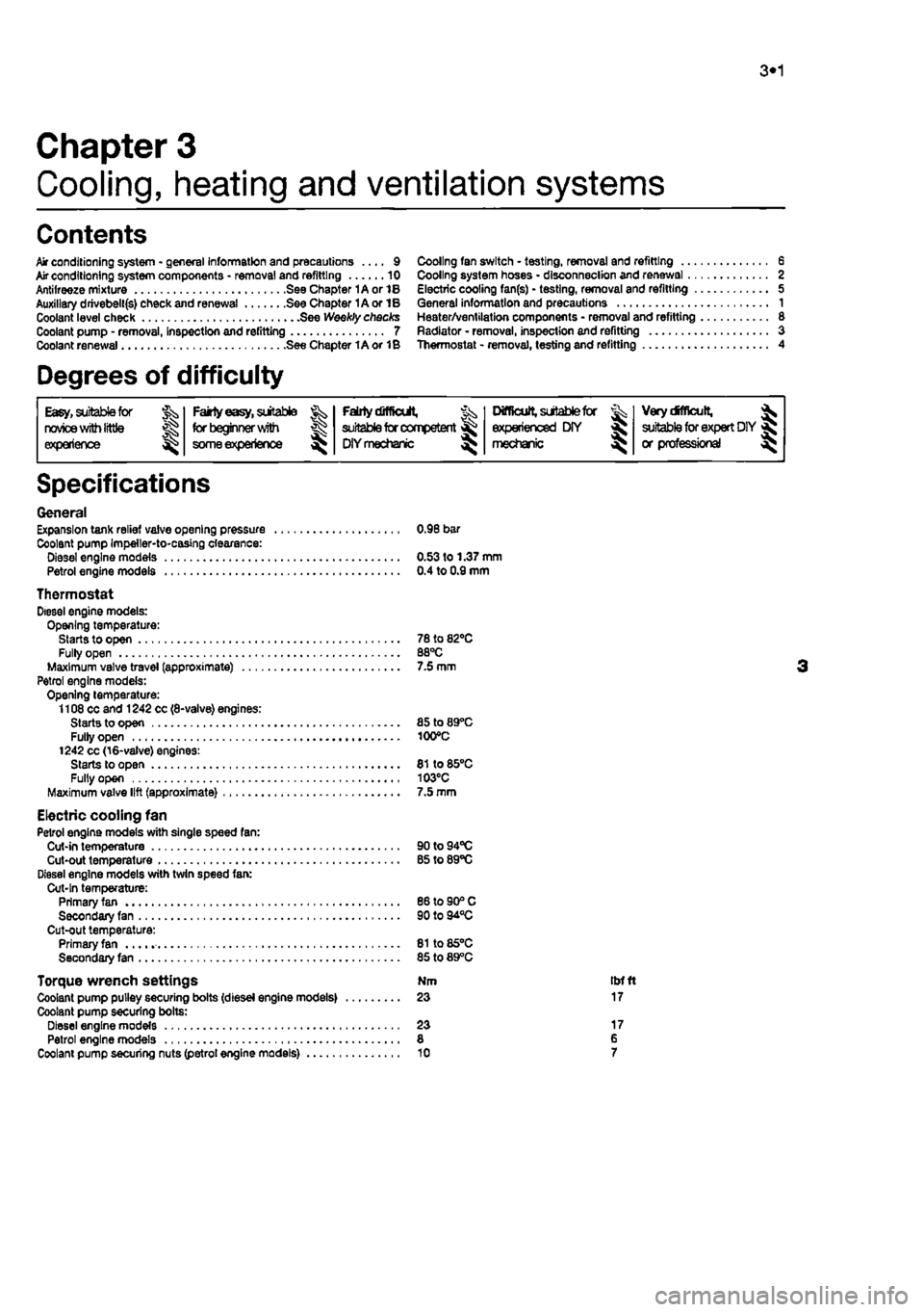
General Expansion tank relief valve opening pressure 0.96 bar Coolant pump Impeller-to-casing clearance: Diesel engine models 0.53 to 1.37 mm Petrol engine models 0.4 to 0.9 mm
Thermostat Diesel engine models: Opening temperature: Starts to open 78 to 82*0 Fully open 88°C Maximum valve travel (approximate) 7.5 mm Petrol engine models: Opening temperature: 1108 cc and 1242 cc (8-valve) engines: Starts to open 85 to 89°C Fully open 100°C 1242 cc (16-valve) engines: Starts to open 81 to 85°C Fully open 103°C Maximum valve lift (approximate) 7.5 mm
Electric cooling fan Petrol engine models with single speed fan: Cut-in temperature 90to94°C Cut-out temperature B5 to 89°C Diesel engine models with twin speed fan: Cut-In temperature: Primary fan 86 to 90® C Secondary fan 90 to 94°C Cut-out temperature: Primary fan 81to85°C Secondary fan 85 to 89°C
Torque wrench settings Nm tbfft Coolant pump pulley securing bolts (diesel engine models) 23 17 Coolant pump securing bolts: Diesel engine models 23 17 Petrol engine models 8 6 Coolant pump securing nuts (petrol engine models) 10 7
Page 118 of 225
3*2 Cooling, heating and ventilation systems
12 If tho pump is stuck, tap It gently using a soft-faced mallet • do not lever between the pump and cylinder block mating faces.
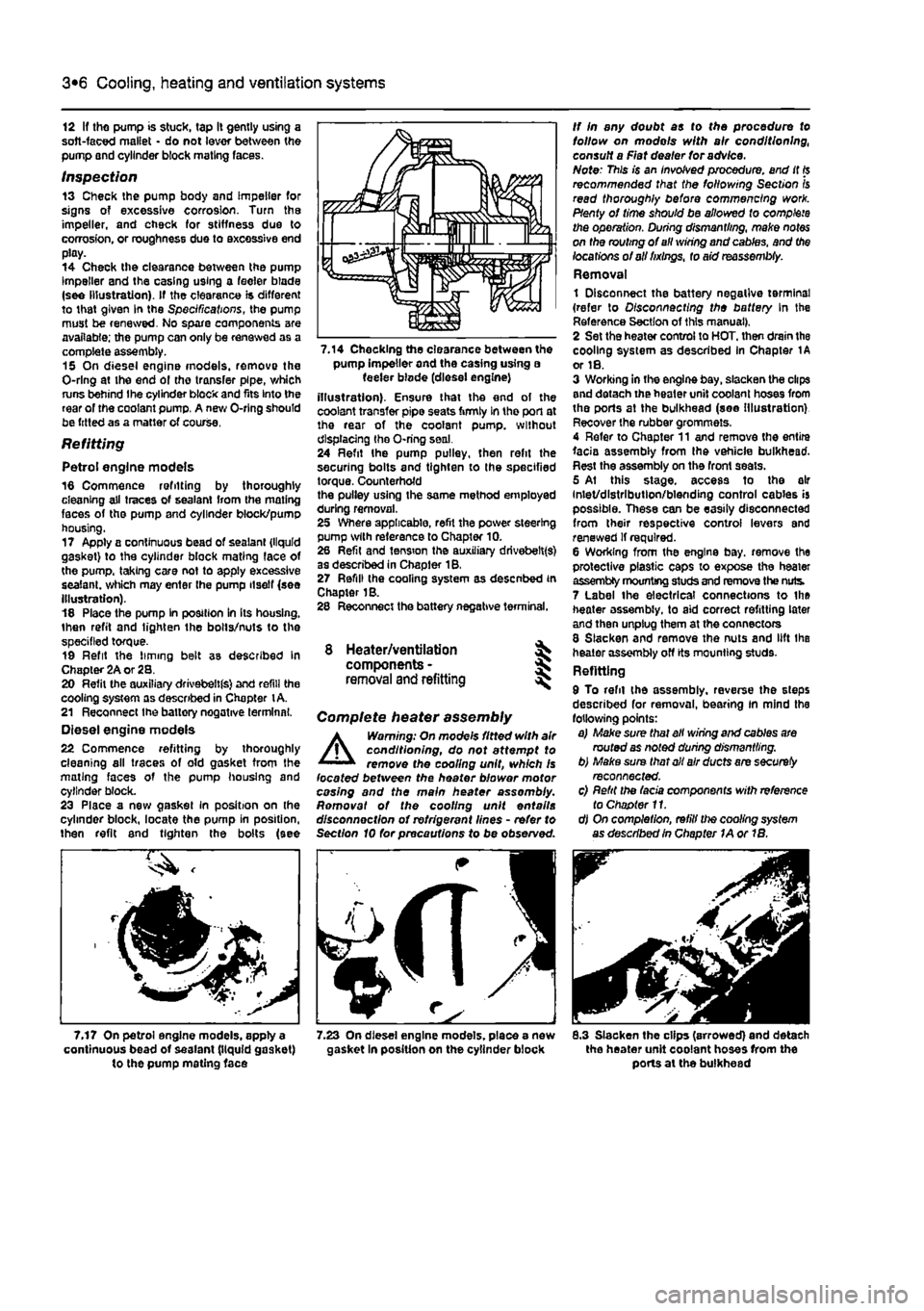
Inspection 13 Check the pump body and impeller for signs of excessive corrosion. Turn the impeller, and check for stiffness due to corrosion, or roughness due to excessive end play. 14 Check the clearance between the pump Impeller and the casing using a feeler blade (see Illustration). If the clearance is different to that given In the Specifications, the pump must be renewed. No spare components are available; the pump can only be renewed as a complete assembly. 15 On diesel engine models, remove the O-rlng at the end ol the transfer pipe, which runs behind Ihe cylinder block and fits Into the rear of the coolant pump. A new O-rlng should be fitted as a matter of course.
Refitting
Petrol engine models 16 Commence refitting by thoroughly cleaning all traces of sealant from the mating faces of the pump and cylinder block/pump housing. 17 Apply a continuous bead of sealant {liquid gasket) to the cylinder block mating face of the pump, taking care not to apply excessive sealant, which may enter the pump itself (see Illustration). 18 Place the pump In position In Its housing, then refit and lighten the bolts/nuts to the specified torque. 19 Refit the liming belt as described In Chapter 2A or 28. 20 Refit the auxiliary drivebeltfs) and refill the cooling system as described in Chapter
t
A. 21 Reconnect Ihe battery negative terminal. Diesel engine models 22 Commence refitting by thoroughly cleaning all traces of old gasket from the mating faces of the pump housing and cylinder block. 23 Place a new gasket in position on (he cylinder block, locate the pump in position, then refit and tighten the bolts (see
7.17 On petrol engine models, apply a continuous bead of sealant (liquid gasket) to the pump mating face
pump Impeller and the casing using a feeler blode (diesel engine) illustration). Ensure that the end of the coolant transfer pipe seats firmly In tho port at the rear of the coolant pump, without displacing the O-ring seal. 24 Refit Ihe pump pulley, then refit the securing bolts and tighten to the specified torque. Counterhofd the pulley using the same method employed during removal. 25 Where applicable, refit the power steering pump with reference to Chapter 10. 26 Refit and tension the auxiliary drivebelt(s) as described in Chapter 18. 27 Refill (he cooling system as desenbed in Chapter 1B. 28 Reconnect the battery negative terminal.
8 Heater/ventilation components - § removal and refitting
Complete heater assembly
A
Warning: On mode's fitted with air conditioning, do not attempt to remove the cooling unit, which Is located between the heater blower motor casing and the main heater assembly. Romovat of the cooling unit entails disconnection of refrigerant lines - refer to Section 10 for precautions to be observed.
rfJS
8.3 Slacken the clips (arrowed) and detach the heater unit coolant hoses from the ports at the bulkhead
Page 121 of 225
4A«1
Chapter 4 Part A:
Fuel system - single-point petrol injection models
Contents
Accelerator cable • removal, refitting and adjustment 4 Air cleaner and inlet system - removal and refitting 2 Air cleaner filter element renewal See Chapter 1A Engine management system components - removal 8nd refitting .. 5 fuel filter renewal See Chapter 1A Fuel injection system - depressurlsatlon 8 Fuel injection system • testing and adjusting 10
Degrees of difficulty
Fuel pump/fuel gauge sender unit - removal and refitting 8 Fuel tank - removal and refitting 7 General information and precautions 1 Idle speed and mixture adjustment See Chapter 1A Inlet air temperature regulator • removal and refitting 3 Inlet manifold - removal and refitting 9 Unleaded petrol - general Information and usage 11
Easy, suitable for Fairty easy, suitable Fairly difficult, Jx suitable for competent ^ OY mechanic ^
DifficUt, suitable tor % Very difficult, ^ novice with Me for begrmer with &
Fairly difficult, Jx suitable for competent ^ OY mechanic ^ experienced DIY > * suitable for expert D(Y JS or professional ^ experience some experience &
Fairly difficult, Jx suitable for competent ^ OY mechanic ^ mechanic > * suitable for expert D(Y JS or professional ^
Specifications
System type Weber-Marelll integrated single-point fuel injection/ignition system
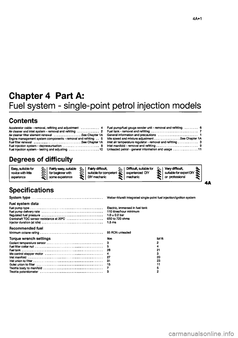
Fuel system data Fuel pump type Electric, Immersed in fuel tank Fuel pump delivery rate 110 litres/hour minimum Regulated fuel pressure 1.0 ± 0.2 bar Crankshaft TDC sensor resistance at 20°C €50 to 720 ohms Injector duration (at idle)
1
£ ms
Recommended fuel Minimum octane rating 95 RON unleaded
Torque wrench settings Nm ibfft Coolant temperature sensor 3 2 Fuel filter collar nut S 4 Fuel tank 28 21 Idle control stepper motor 4 3 Inlet manifold 27 20 Inlet union to filter 31 23 Outlet union to filter 15 11 Throttle body to manifold 7 5 Throttle potentiometer 3 2
Page 124 of 225
4A*2 Fuel system - single-point petrol Injection models
motor c) Ensure that all hoses are correctly reconnected and, where necessary, that their retaining clips are securely tightened. d) Adjust the accelerator cable as described In Section 4.
Fuel injector Note: If a faulty Injector Is suspected, before condemning the Injector, it is worth vying the effect of one of the proprietary Injector cleaning treatments. Removal 8 Remove the air cleaner and air duct as described In Section 2. 9 Disconnect the wiring then unscrew the mounting screws and remove Ihe Injector from the throttle body. Refitting 10 Refitting is a reversal of removal.
Fuel pressure regulator
Removal 11 Remove Ihe air cleaner and air duel as described In Section 2. 12 Using a marker pen. make alignment marks between the regulator cover end the throttle body, then undo the four retaining
screws. As the screws are loosened, place a rag over the cover to catch any fuel spray which may be released. 13 Lift off the cover, then remove the spring and withdraw the diaphragm, noting Its correct fitted orientation. Remove all traces of dirt, and examine the diaphragm for signs of splitting. If damage Is found, it will be necessary to renew the complete upper throttle body assembly. Refitting 14 Refitting is a reversal of removal ensuring that the diaphragm and cover are fitted the correct way round, and that the retaining screws are securely tightened,
Idle control stepper motor
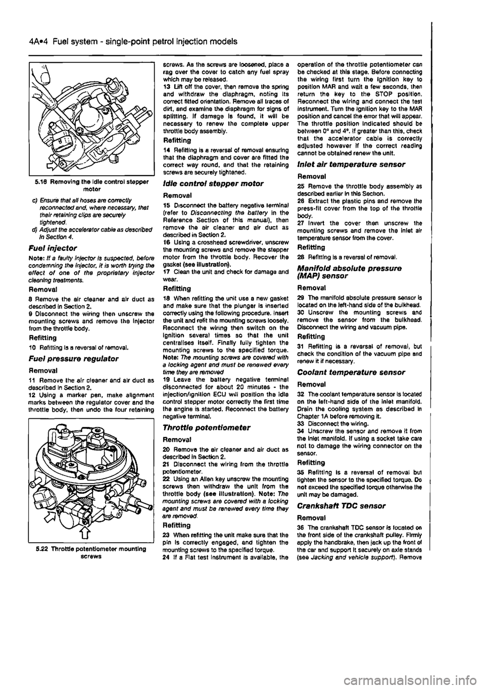
Removal 15 Disconnect the battery negative terminal (refer to Disconnecting the battery In the Reference Section of this manual), then remove the air cleaner and air duct as described in Section 2. 16 Using a crosshead screwdriver, unscrew the mounting screws and remove the stepper motor from the throttle body. Recover the gaskei (see illustration). 17 Clean the unit and check for damage and wear. Refitting 18 When refitting the unit use a new gasket and make sure that the plunger is inserted correctly using the following procedure. Insert the unit and refit the mounting screws loosely. Reconnect the wiring then switch on the ignition several times so that the unit centralises itself. Finally fully tighten the mounting screws to the specified torque. Note: The mounting screws are covered with a locking agent and must be renewed every time they are removed 19 Leave the battery negative terminal disconnected for about 20 minutes - the injection/ignition ECU will position the Idle control stepper motor correctly the first time the engine is started. Reconnect the battery negative terminal.
Throttle potentiometer
Removal 20 Remove the air cleaner and air duct as described in Section 2. 21 Disconnect the wiring from the throttle potentiometer. 22 Using an Allen key unscrew the mounting screws then withdraw the unit from the throttle body (see Illustration). Note: The mounting screws ere covered with a locking agent and must be renewed every time they are removed. Refitting 23 When refitting the unit make sure that the pin Is correctly engaged, and tighten the mounting screws to the specified torque. 24 If a Rat test Instrument is available, the
operation of the throttle potentiometer can be checked at this stage. Before connecting the wiring first turn Ihe ignition key to position MAR and wait a few seconds, then return the key to the STOP position, Reconnect the wiring and connect the test instrument. Turn the Ignition key to the MAR position and cancel the error that will appear. The throttle position Indicated should be between 0° and 4°. If greater than this, check thai the accelerator cable is correctly adjusted however If the correct reading cannot be obtained renew the unit.
Inlet air temperature sensor
Removal 25 Remove the throtlle body assembly as described earlier In this Section. 28 Extract the plastic pins and remove the press-fit cover from the top of the throttle body. 27 Invert the cover then unscrew the mounting screws and remove the Inlet air temperature sensor from the cover. Refitting 28 Refining Is a reversal of removal.
Manifold absolute pressure (MAP) sensor
Removal 29 The manifold absolute pressure sensor is located on the left-hand side of the bulkhead. 30 Unscrew the mounting screws and remove the sensor from the bulkhead, Disconnect the wiring and vacuum pipe. Refitting 31 Refitting is a reversal of removal, but check the condition of the vacuum pipe and renew it if necessary.
Coolant temperature sensor
Removal 32 The coolant temperature sensor Is located on the left-hand side of the inlet manifold. Drain the cooling system as described In Chapter 1A before removing it. 33 Disconnect the wiring. 34 Unscrew the sensor and remove It from the Inlet manifold. If using a socket take care not to damage Ihe wiring connector on the sensor. Refitting 35 Refitting Is a reversal of removal bui tighten Ihe sensor to the specified torque. Do not exceed the specified torque otherwise the unit may be damaged.
Crankshaft TDC sensor
Removal 36 The crankshaft TDC sensor Is located on the front side of the crankshaft pulley. Firmly apply the handbrake, then jack up the front of the car Bnd support It securely on axle stands (see Jacking end vehicle support). Remove 5.22 Throttle potentiometer mounting screws
Page 127 of 225
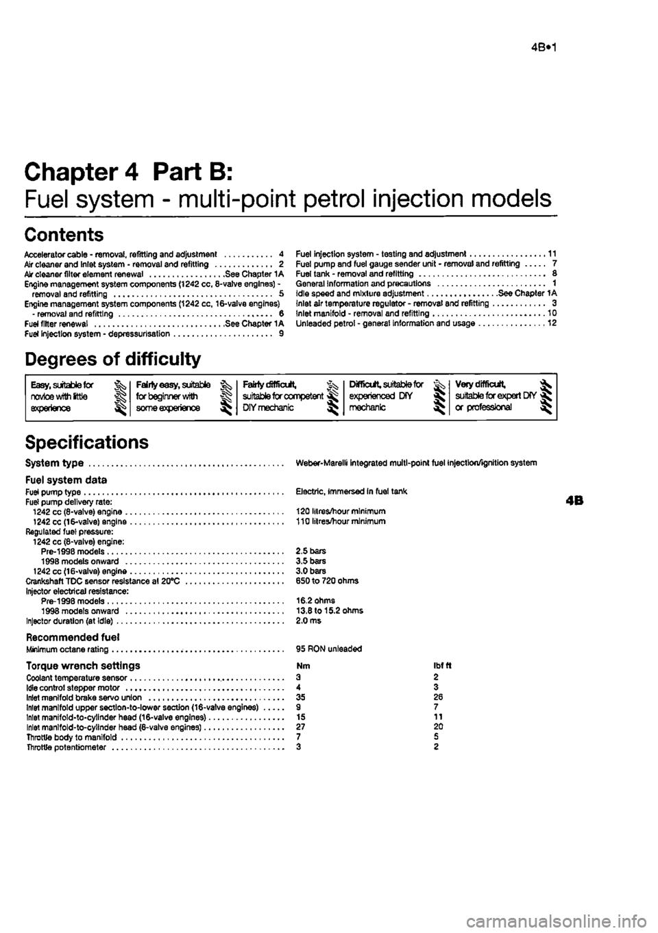
4B*1
Chapter 4 Part B:
Fuel system - multi-point petrol injection models
Contents
Accelerator cable - removal, refitting and adjustment 4 Air cleaner and Inlet system • removal and refitting 2 Air cleaner filter element renewal See Chapter 1A Engine management system components (1242 cc, 8-valve engines) -removal and refitting 5 Engine management system components (1242 cc, 16-valve engines) - removal and refitting 6 Fuel filter renewal See Chapter 1A Fuel Injection system - depressurisation 9
Degrees of difficulty
Fuel injection system - testing and adjustment 11 Fuel pump and fuel gauge sender unit - removal and refitting 7 Fuel tank - removal and refitting 8 General Information and precautions 1 Idle speed and mixture adjustment See Chapter 1A Inlet air temperature regulator - removal and refitting 3 Inlet manifold - removal and refitting 10 Unleaded petrol • general Information and usage 12
Easy, suitable
for ^
novice with
Ittie experience ^
Fairly
easy,
suitable Jk for beginner
with
® someexperiencs ^
FaMycSffiait, J^ suitable
for
competent ^
DIY mechanic
^
Difficult
suitable
for experienced BY SJ mechanic ^
Very difficult,
^
suitable
for expert
DIY
jR or professional ^
Specifications
System type
Fuel system data Fuel pump type Fuel pump delivery rate: 1242 cc (8-vatve) engine 1242 cc (16-valve) engine Regulated fuel pressure: 1242 cc (8-vaive) engine: Pre-1998 models 1998 models onward 1242 cc (16*valve) engine Crankshaft TDC sensor resistance al 20°C Injector electrical resistance: Pre-1998 models 1998 models onward Injector duration (at Idle)
Recommended fuel Minimum octane rating
Torque wrench settings Coolant temperature sensor
Idle
control stepper motor Inlet manifold brake servo union Inlet manifold upper section-to-lower section (16-valve engines) Inlet manifold-to-cylinder head (16-valve engines) Inlet manlfold-to-cylinder head (8-valve engines) Throttle body to manifold Throttle potentiometer
Weber-Marelli integrated multi-point fuel injection/ignition system
Electric, immersed In fuel tank
120 Hires/hour minimum 110 litres/hour minimum
2.5 bars 3.5 bars 3.0 bars 650 to 720 ohms
16.2 ohms 13.8 to 15.2 ohms 2.0 ms
95 RON unleaded
Nm Ibfft a 2 4 3 35 26 9 7 15 11 27 20 7 5 3 2
Page 137 of 225
Fuel system - diesel models 4C*3
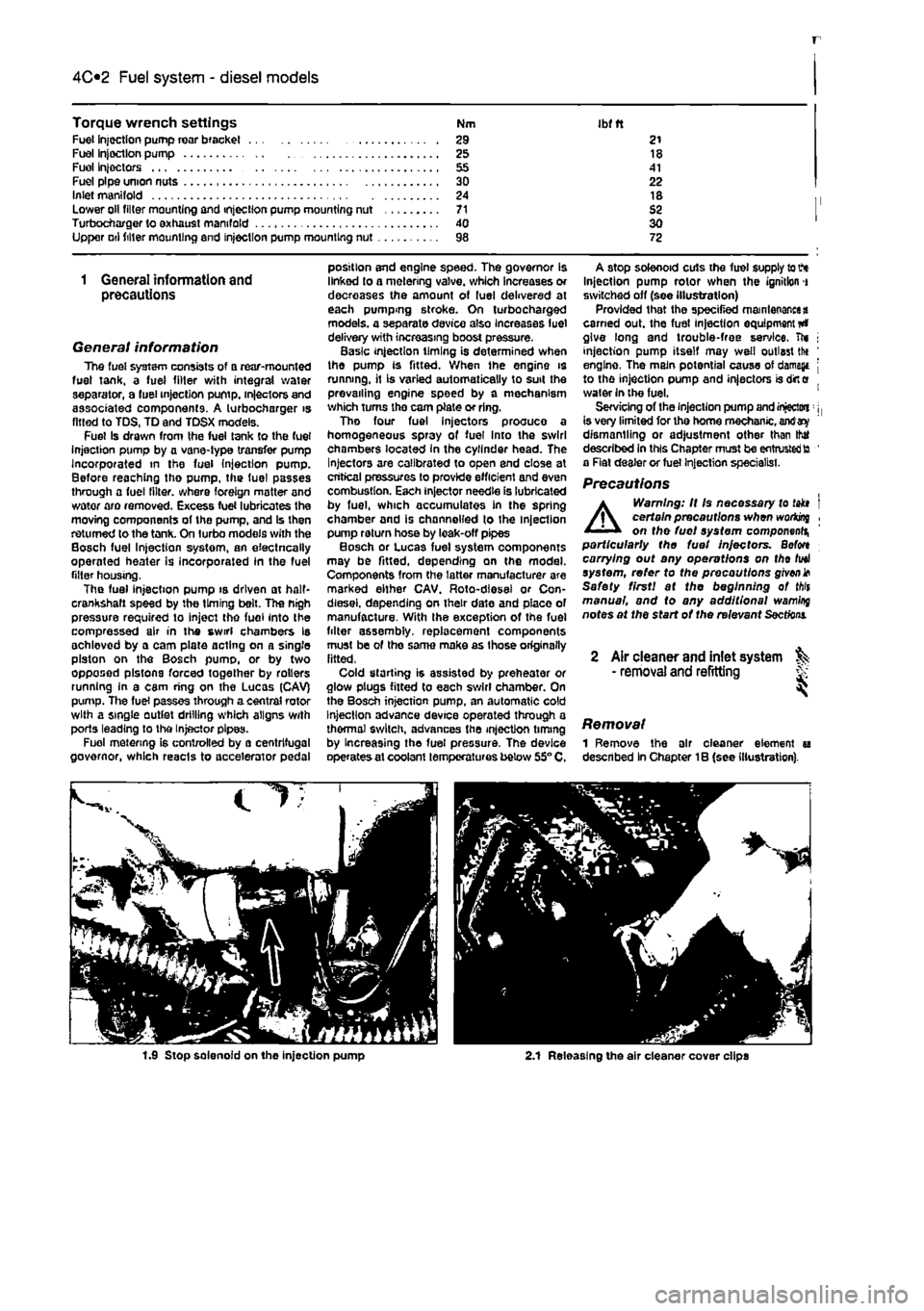
Torque wrench settings Nm Ibfft Fuel injection pump roar bracket .. . 29 21 Fuel Injection pump .... 25 18 Fuel Injectors 41 Fuel pipe union nuts .... 30 22 Inlet manifold .... 24 18 Lower oil tiller mounting and injection pump mounting nut ..... .... 71 S2 Turbocnarger to exhaust manifold .... <10 30 Upper Dtl filter mounting end injection pump mounting nut 98 72
1 General information and precautions
General information The fuel system consists of a rear-mounted fust tank, a fuel filter with integral water separator, a fuel injection pump, in|eciors and associated components. A turbocharger is fitted to TDS, TD and TDSX models. Fuel Is drawn from the fuel tank to the fuel Injection pump by a vane-type transfer pump Incorporated in the fuel injection pump. Before reaching tho pump, the fuel passes through a fuel filter, where foreign matter and water aro removed. Excess fuel lubricates the moving components of the pump, and Is then returned to the tank. On turbo models with the Bosch fuel Injection systom, an eiectncally operated heater is incorporated In the fuel filter housing. The fuel injection pump is driven at half-crankshaft speed by the timing belt. The nigh pressure required to inject tho fuel into the compressed air in the swirl chambers Is achlovod by a cam plate acting on a single piston on the Bosch pumo, or by two opposed pistons forced together by rollers running in a cam ring on the Lucas (CAV) pump. Tlie fuel passes through acentral rotor with a single outlet drilling which aligns With ports leading to the Injector pipes. Fuel metering is controlled by a centrifugal governor, which reacts to accelerator pedal
position end engine speed. The governor is linked lo a metering valve, which increases or decreases the amount of fuel delivered at each pumping stroke. On turbocharged models, a separate device also Increases luel delivery with increasing boost pressure. Basic injection timing is determined when the pump is fitted. When the engine is running, it Is varied automatically to suit the prevailing engine speed by a mechanism which turns the cam plate or ring, Tho four fuel injectors proouco a homogeneous spray of fuel Into the swirl chambers located In the cylinder head. The Injectors are calibrated to open end close at critical pressures lo provide efficient and even combustion. Each injector needle is lubricated by fuel, which accumulates In the spring chamber and is channelled to the injection pump return hose by loak-off pipes Bosch or Lucas fuel system components mBy be fitted, depending on the model. Components from the latter manufacturer are marked either CAV. Roto-dlesel or Con-diesel. depending on their date and place of manufacture. With the exception of the fuel filter assembly, replacement components must be of tho same make as those originally fitted. Cold starting is assisted by preheater or glow plugs fitted to each swirl chamber. On the Bosch injection pump, an automatic cold Injection advance device operated through a thermal switch, advances the injection timing by Increasing the fuel pressure. The device operates at coolant temperatures below 55° C,
A stop solenoid cuts the fuel supply to V* Injection pump rotor when the ignition i switched off (see illustration) Provided that the specified maintenance* earned out. the fuel injection equipment #» give long and trouble-free service, ft* j injection pump itself may well outlast tlx ' engine, The main potential cause of damage j to the injection pump and injectors is dirt e water in the fuel. 1 Servicing of the injection pump and injectwi: j, is very limited for tho home mechanic, antf dismantling or adjustment other than thtf described In this Chapter must be entrusted to ' a Rat dealer or fuel Injection specialist.
Precautions
A
Warning: It Is necessary to takt I certain precautions when woriong , on the fuel system component^ particularly the fuel Injectors. Befon carrying out any operations on tho fuel system, refer to the precautions given* Safety first! at the beginning of Mis manual, and to any additional wamlrq notes at the start of the relevant
Sections.
2 Air cleaner and inlet system ^ • removal and refitting S
Removal 1 Remove the air cleaner element u described In Chapter 1B (see illustration).
1.9 Stop solenoid on the injection pump 2.1 Releasing the air cleaner cover clips
Page 140 of 225
Fuel system - diesel models
4C*3
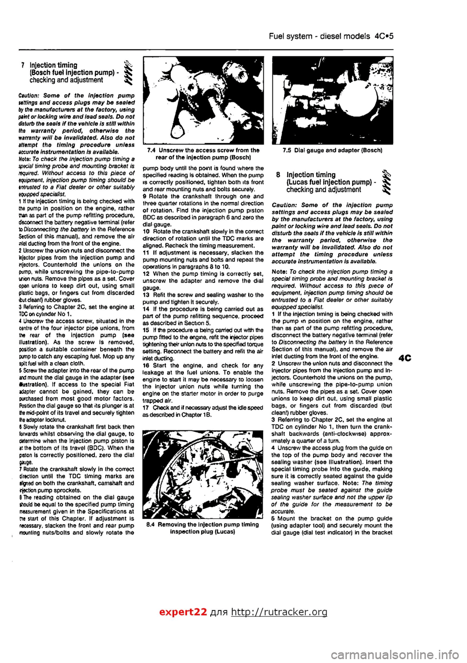
7.4 Unscrew the access screw from the 7.5 Dial gauge and adapter (Bosch) rear of the Injection pump (Bosch)
7 Injection timing ^ (Bosch fuel injection pump) -checking and adjustment ^
Caution: Some of the Injection pump uttlngs and access plugs may be sealed ty the manufacturers at the factory, using
paint
or locking wire and lead seals. Do not
disturb
the seals If the vehicle is still within the warranty period, otherwise the warranty will be invalidated. Also do not attempt the timing procedure unless
accurate
Instrumentation Is available. Note: To check the injection pump timing a special
timing
probe and mounting bracket is required. Without access to this piece of
tquipment.
injection pump timing should be intrusted to a Fiat dealer or other suitably
eqwpped
specialist. 1
H
the Injection timing is being checked with ffie pump in position on the engine, rather rian as part ot the pump refitting procedure, disconnect the battery negative terminal (refer to
Disconnecting
the battery in the Reference S«ction of this manual), and remove the air rtel ducting from the front of the engine. 2 Unscrew the union nuts and disconnect the injector pipes from the Injection pump and injectors. Counterhold the unions on the pump, while unscrewing the pipe-to-pump irion
nuts.
Remove the pipes as a set. Cover open unions to keep dirt out, using small plastic bags, or fingers cut from discarded
ibut clean!)
rubber gloves. 3 Referring to Chapter 2C, set the engine at
TDC on
cylinder No 1. 4 Unscrew the access screw, situated In the centre of the four injector pipe unions, from the rear of the Injection pump (see illustration). As the screw Is removed, position a suitable container beneath the
pump
to catch any escaping fuel, Mop up any tpilt fuel with a clean cloth. 5 Screw the adapter into the rear of the pump
and
mount the dial gauge in ihe adapter (see •ustration). If access to the special Fiat *Japter cannot be gained, they can be purchased from most good motor factors. Position the dial gauge so that its plunger is at
Ifce
mid-point of its travel and securely tighten Ite adapter locknut. 6 Slowly rotate the crankshaft first back then towards whilst observing the dial gauge, to ctotermlne when the Injection pump piston is
a',
the bottom of Its travel (BDC), When the pston Is correctly positioned, zero the dial
7 Rotate the crankshaft slowly in the correct direction until the TDC timing marks are tfjned on both the crankshaft, camshaft and rjecbon pump sprockets.
6
The reading obtained on the dial gauge should be equal to the specified pump timing measurement given in the Specifications at ew start of this Chapter, If adjustment is necessary, slacken the fronl and rear pump mounting nuts/bolts and slowly rotate the
pump body until the point is found where the specified reading Is obtained. When the pump is correctly posilioned, tighten both its front and rear mounting nuts and bolts securely. 9 Rotate the crankshaft through one and three quarter rotations in the normal direction of rotation. Find the injection pump piston BDC as described in paragraph 6 and zero the dial gauge. 10 Rotate the crankshaft slowly in the correct direction of rotation until the TDC marks are aligned. Recheck the timing measurement. 11 If adjustment is necessary, slacken the pump mounting nuts and bolts and repeat the operations In paragraphs 8 to 10. 12 When the pump timing Is correctly set, unscrew the adapter and remove the dial gauge. 13 Refit the screw and sealing washer to the pump and tighten it securely. 14 If the procedure is being carried out as part of the pump refitting sequence, proceed as described in Section 5, 15 If the procedure is being carried out with the pump fitted to the engine, refit the injector pipes tightening their union nuts to the specified torque setting. Reconnect the battery and refit the air inlet ducting. 16 Start the engine, and check for any leakage at the luel unions. To enable the engine to start it may be necessary to loosen the injector union nuts while turning tho engine on the starter motor in order to purge trapped air. 17 Check and if necessary adjust the idle speed as described in Chapter 1B.
8.4 Removing the injection pump timing inspection plug (Lucas)
8 injection timing ^ (Lucas fuel injection pump) - ^ checking
and
adjustment ^
Caution: Some of the injection pump settings and access plugs may be sealed by the manufacturers at the factory, using paint or locking wire and lead seo/s. Do not disturb the seals if the vehicle Is still within the warranty period, otherwise tho warranty will be Invalidated. Also do not affempf the timing procedure unless accurate instrumentation is available.
Note: To check the Injection pump timing a speciai timing probe and mounting bracket Is required. Without access to this piece of equipment, injection pump timing should be entrusted to a Fiat dealer or other suitably equipped specialist. 1 If the injection timing is being checked with the pump tn position on the engine, rather than as part of the pump refitting procedure, disconnect the battery negative terminal (refer to Disconnecting the battery in the Reference Section of this manual), and remove the air inlet ducting from the front of the engine. 2 Unscrew the union nuts and disconnect the injector pipes from the Injection pump and In-jectors. Counterhold the unions on the pump, while unscrewing the pipe-to-pump union nuts. Remove the pipes as a set. Cover open unions to keep dirt out. using smalt plastic bags, or fingers cut from discarded (but clean!) rubber gloves. 3 Referring to Chapter 2C, set the engine at TDC on cylinder No 1, then turn the crank-shaft backwards (anti-clockwise) approx-imately a quarter of a turn. 4 Unscrew the access plug from the guide on the top of the pump body and recover the sealing washer (soe Illustration). Insert the special liming probe Into the guide, making sure it Ib correctly seated against the guide seating washer surface. Note: The timing probe must be seated against the guide sealing washer surface and not the upper lip of the guide for the measurement to be accurate. 5 Mount the bracket on the pump guide (using adapter tool) and securely mount the dial gauge {dial test indicator) In the bracket
expert22 fl/i* http://rutracker.org
Page 141 of 225
Fuel system - diesel models 4C*3
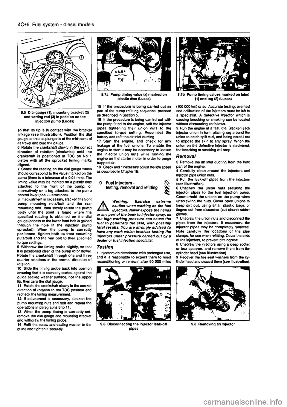
8.5 Dial gauge (1), mounting bracket (2) and setting rod (3) In position on the injection pump (Lucas)
so that Its tip Is In contact with the bracket linkage (see Illustration). Position the dial gauge so that its plunger is at the mid-point of its travel and zero the gauge. 6 Rotate the crankshaft slowly in the correct direction of rotation (clockwise) until the crankshaft is positioned at TDC on No 1 piston with ell the sprocket timing marks aligned. 7 Check the reading on the dial gauge which should correspond to the value marked on the pump (there is a tolerance of * 0.04 mm). The timing value may be marked on a plastic disc attached to the front of the pump, or alternatively on a tag attached to Ihe pump control lever (see illustrations). 8 If adjustment is necessary, slacken the front pump mounting nuts/bolt and the raar mounting bolt, then slowly rotate tne pump body until the point is found where the specified reading is obtained on the dial gauge (access to the lower front bolt is gained through the hole in the injection pump sprocket). When the pump Is correctly positioned, tighten both its front mounting nuta/bolt and the rear bolt to their specified torque settings. 9 Withdraw the timing probe slightly, so that it
8.7a Pump timing value (x) marked on plastic diso (Lucas)
15 If the procedure is being carried out as part of the pump refilling sequence, proceed as described in Section 5. 16 If the procedure is being carried out with the pump fitted to the engine, refit the injector pipes tightening their union nuts to the specified torque setting. Reconnect the battery and refit the air inlet ducting. 17 Start the engine, and check for any leakage at the fuel unions. To enable the engine to start it may be necessary to loosen tho injector union nuts while turning the engine on the starter motor in order to purge trapped air. 18 Check and If necessary adjust the Idle speed as described In Chapter 1B.
9 Fuel Injectors -testing, removal and refitting Sk ^
A
Warning: Exercise extreme caution when working on the fuel injectors. Never expose the hands or any part of the body to Injector spray, as the high working pressure can cause the fuel to pen ot rate the skin, with possibly fatal results. You are strongly advised to have any work which involves testing the injectors under pressure carried out by a dealer or fuel Injection specie list.
Testing 1 Injectors do deteriorate with prolonged uso, and it is reasonable to expect them to need reconditioning or renewal after 60 000 miles
8.7b Pump timing values marked on label (1) and tag (2) (Lucas)
(100 000 km) or so. Accurate testing, overhaul and calibration of the Injectors must be left to a specialist. A defective injector which Is causing knocking or smoking can be located without dismantling as follows. 2 Run the engine at a fast idle. Slacken each Injector union In turn, placing rag around the union to catch spilt fuel, and being careful not to exposa the skin to any spray. When tho union on the defective Injector is slackened, the knocking or smoking will stop.
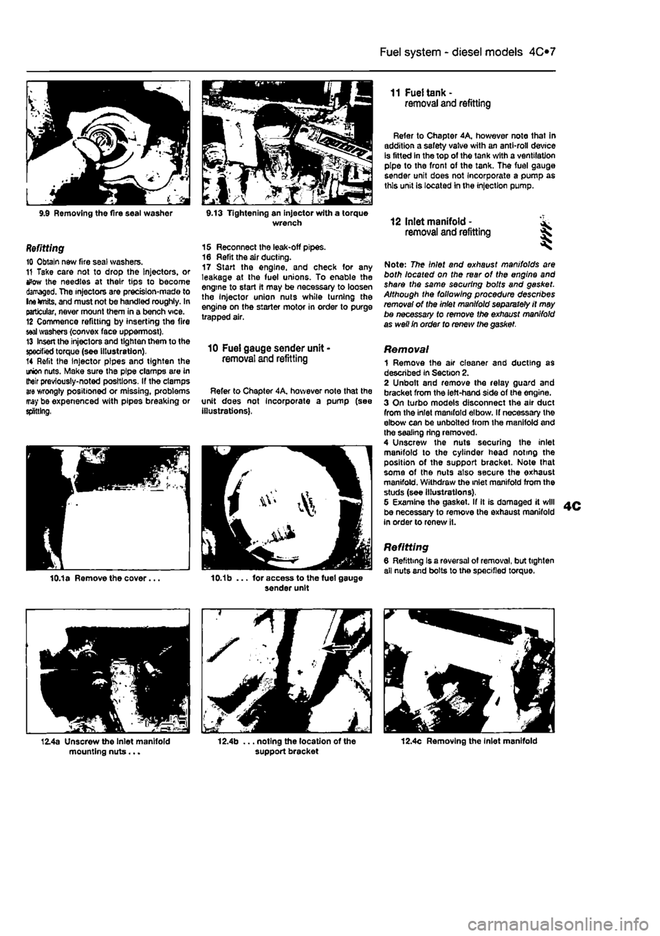
Removal 3 Remove ihe air Inlet ducting from tho front part of the onglne. 4 Carefully clean around the Injectors and injector pipe union nuts. 5 Pull the leak-off pipes from the injectors (see illustration). 6 Unscrow the union nuts securing Ihe injector pipes to the fuel Injection pump. Counterhold the unions on the pump when unscrewing the nuts. Cover open unions lo keep dirt out, using small plastic bags, or fingers cut from discarded (but clean!) rubber gloves. 7 Unscrew the union nuts and disconnect the pipes from the ln|ectors, If necessary, the Injector pipes may be completely removed-Note carefully the locations of the pipe clamps, for use when refitting. Cover tho onds ot (he injectors, to prevent dirt ingress. 8 Unscrew the injectors using a deep socket or box spanner, and remove Ihem from the cylinder head (see Illustration). 9 Recover the tire seal washers from the cy-linder head and discard them (see illustration).
9.5 Disconnecting the Injector leak-off pipes 9.8 Removing an injector
Page 142 of 225
Fuel system - diesel models
4C*3
9.9 Removing the fire seal washor 9.13 Tightening an injector with a torque wrench
Refitting 10 Obtain new fire seal washers. 11 Take care not to drop the Injectors, or tfow the needles at their tips to become damaged. The injectors are prectsion-mado to Ine knits, and must not be handled roughly. In particular, never mount them in a bench vice. 12 Commence refitting by inserting the fire
seal
washers {convex face uppermost}. 13 Insert the injectors and tighten them to the specified torque (see illustration). 14 Refit the injector pipes and tighten the union nuts. Make sure the pipe clamps are in Iteir previously-noted positions. If the clamps
are
wrongly positioned or missing, problems may be expenenced with pipes breaking or splitting,
15 Reconnect the leak-off pipes. 16 Refit the air ducting. 17 Start the engine, and check for any leakage at the fuel unions. To enable the engine to start it may be necessary to loosen the Injector union nuts while turning the engine on the starter motor in order to purge trapped air.
10 Fuel gauge sender unit -removal and refitting
Refer to Chapter 4A, hov/ever note that the unit does not Incorporate a pump (see illustrations).
11 Fuel tank -removal and refitting
Refer to Chapter 4A, however note that in addition a safety valve with an anti-roll device is fitted in the top of the tank with a ventilation pipe to the front of the tank. The fuel gauge sender unit does not Incorporate a pump as this unit is located In the injection pump.
12 Inlet manifold - ^ removal and refitting %
Note: The Inlet and exhaust manifolds are both located on the rear of the engine and share the same securing bolts and gasket. Although the following procedure describes removal of the Inlet manifold separately it may be necessary to remove the exhaust manifold as well In order to renew the gasket.
Removal 1 Remove the air cleaner and ducting as described in Section 2. 2 Unbolt and remove the relay guard and bracket from the left-hand side of the engine. 3 On turbo models disconnect the air duct from the inlet manifold elbow. If necessary the elbow can be unbolted from the manifold and the sealing ring removed. 4 Unscrew the nuts securing the inlet manifold to the cylinder head noting the position of the support bracket. Note lhat some of the nuts also secure the exhaust manifold. Withdraw the inlet manifold from the studs (see illustrations), 5 Examine the gasket. If It is damaged it will be necessary to remove the exhaust manifold in order to renew it.
Refitting 6 Refitting Is a reversal of removal, but tighten all nuts and bolts lo the specified torque.
12.4c Removing the Inlet manifold
Page 143 of 225
Fuel system - diesel models 4C*3
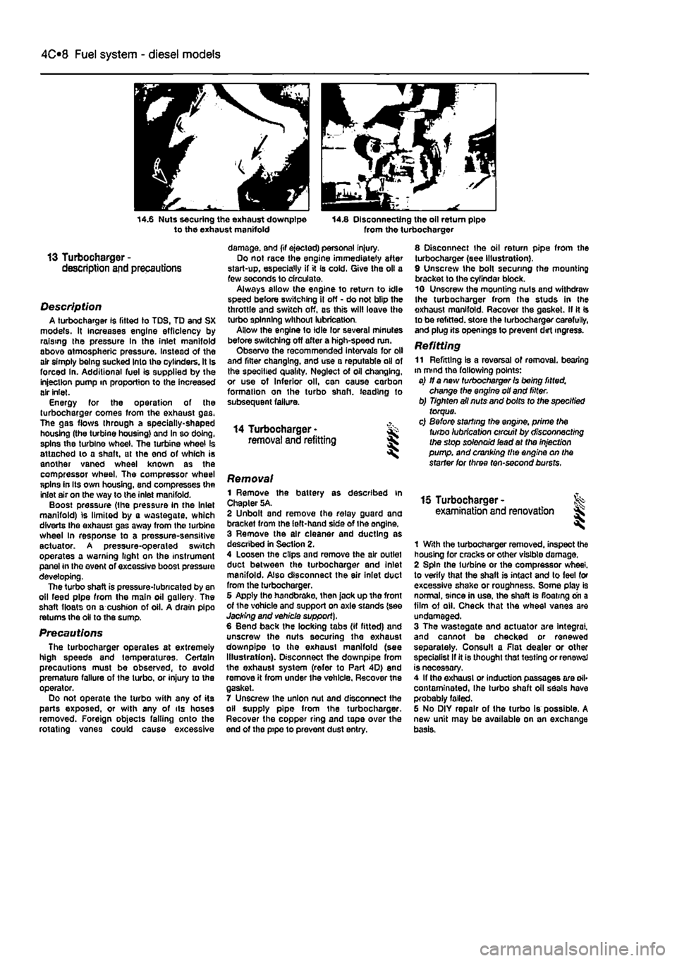
14.6 Nuts securing the exhaust downpipe to the exhaust manifold 14.8 Disconnecting the oil return pipe from tho turbocharger
13 Turbocharger -description and precautions
Description A turbocharger 1$ fitted to TDS, TD and SX models. It increases engine efficiency by raising the pressure In the inlet manifold above atmospheric pressure. Instead of the air simply being sucked Into the cylinders. It Is forced in. Additional fuel is supplied by the injection pump in proportion to the increased air inlet. Energy for the operation of the turbocharger comes from the exhaust gas. The gas flows through a specially-shaped housing (the turbine housing) and In so doing, spins the turbine wheel. The turbine wheel is attached lo a shaft, at the end of which is another vaned wheel known as the compressor wheel, The compressor wheel spins in Its own housing, snd compresses the inlet air on the way to the inlet manifold. Boost pressure (the pressure in the Inlet manifold) is limited by a wastegate, which diverts Ihe exhaust gas away from the turbine wheel In response to a pressure-sensitive actuator. A pressure-operaled switch operates a warning light on the instrument panel in the event of excessive boost pressure developing. The turbo shaft is pressure-lubricated by an oil feed pipe from the main oil gallery The shaft floats on a cushion of oil. A drain pipo returns the oil to the sump.
Precautions The turbocharger operates at extremely high speeds and temperatures. Certain precautions must be observed, to avoid premature failure of the turbo, or injury to the operator. Do not operate the turbo with any of its parts exposed, or with any of ils hoses removed. Foreign objects falling onto the rotating vanes could cause excessive
damage, and (if ejected) personal injury. Do not race the engine immediately after start-up, especially if it Is cold. Give the oil a few seconds lo circulate. Always allow the engine to return to idle speed before switching il off - do not blip the throttle and switch off, as this will leave the turbo spinning without lubrication. Allow the engine to idle lor several minutes before switching off after a high-speed run. Observe the recommended intervals for oil and filter changing, and use a reputable oil of the specified quality. Neglect of oil changing, or use of Inferior oil, can cause carbon formation on the turbo shaft, leading to subsequent failure.
14 Turbocharger -removal and refitting
8 Disconnect the oil return pipe from the turbocharger (see Illustration). 9 Unscrew the bolt securing the mounting bracket to the cyfindar block. 10 Unscrew the mounting nuts and withdraw the turbocharger from the studs in Ihe exhaust manifold. Recover the gasket. II It Is to be refitted, store the turbocharger carefully, and plug its openings to prevent dirt ingress.
Refitting 11 Refitting Is a reversal of removal, bearing in mind the fallowing points: a) if a new turbocharger Is being fitted, change the engine oil and filter. b) Tighten ail nuts and bolts to the specified torque. c) Before starting the engine, prime the turbo lubrication circuit by disconnecting the stop solenoid iead at the injection pump, and cranking the engine on the starter for three ten-second bursts.
Removal 1 Remove the battery as described in Chapter 5A. 2 Unbolt and remove the relay guard and bracket from the left-hand side of Ihe engine. 3 Remove the air cleaner and ducting as descnbed in Section 2. 4 Loosen the clips and remove the air outlet duct between tho turbocharger and inlet manifold. Also disconnect the air inlet duct from the turbocharger. 6 Appty the handbrake, then jack up tho front of the vohicle and support on axle stands (see Jacking and vehicle support). 6 Bend back the locking tabs (if fitted) and unscrew the nuts securing the exhaust downpipe lo the exhaust manifold (see Illustration). Disconnect the downpipe from the exhaust system (refer to Part 4D) end remove it from under the vehicle. Recover tne gasket. 7 Unscrew ihe union nut and disconnect the oil supply pipe from the turbocharger. Recover the copper ring and tape over the end of the pipe 10 prevent dust entry.
15 Turbocharger -examination and renovation l
1 With the turbocharger removed, inspect the housing for cracks or other visible damage. 2 Spin the turbine or the compressor wheel, to verify that the shaft is intact and to feel for excessive shake or roughness. Some play is normal, since in use, the shaft is floating on a film of oil. Check that the wheel vanes are undamaged. 3 The wastegate and actuator are Integral, and cannot be checked or renewed separately. Consul! a Flat dealer or other specialist If it is thought that testing or renewal is necessary. 4 If tho exhaust or induction passages are ail* contaminated, Ihe turbo shaft oil seals have probably failed. 6 No DIY repair of the turbo is possible. A new unit may be available on an exchange basis,