1.7 diesel FIAT PUNTO 1995 176 / 1.G Workshop Manual
[x] Cancel search | Manufacturer: FIAT, Model Year: 1995, Model line: PUNTO, Model: FIAT PUNTO 1995 176 / 1.GPages: 225, PDF Size: 18.54 MB
Page 2 of 225

Fiat Punto
Service and Repair Manual
A K Legg LAEMIMI and Spencer Drayton
Models covered P251 •272 • WAC2>
Fiat Punto Hatchback, including Selecta and special/limited editions Petrol engines: 1.1 litre (1108 cc) and 1,2 litre (1242 cc, 8-valve and 16-valve) Diesel & turbo-dlesel engines: 1.7 litre (1698 cc)
Does NOT cover 1.4 litre (1372 cc) or 1.6 litre (1581 cc) petrol engines, or Cabriolet
©Haynos Publishing 1999 KLWH A book in the Haynes Service end Ropalr Manual Series
All rights reserved. No part of this book may bo reproduced or transmitted in any form or by any means, electronic or mechanical, Including photocopying, recording or by any information storage or retrieval system, without permission In writing from the copyright hokJer.
ISBN 1 85960 561 3
British Library Cataloguing tn Publication Data A catalogue record for this book Is available from the British Ubrary.
Printed by J H Haynes & Co. Ltd, Sparkford, Nr Yeovil, Somerset BA22 7JJ
Haynes Publishing
Sparkford. Nr Yeovil. Somerset BA22 7JJ, England
Haynes North America, Inc
681 Lawrence Drive, Newbury Park. Califomio 91320. USA
Editions Haynes S.A. Tour Aurora - La
D6
expert22 fl/i* http://rutracker.org
Page 12 of 225

Weekly checks o.n
Ulllllli
B
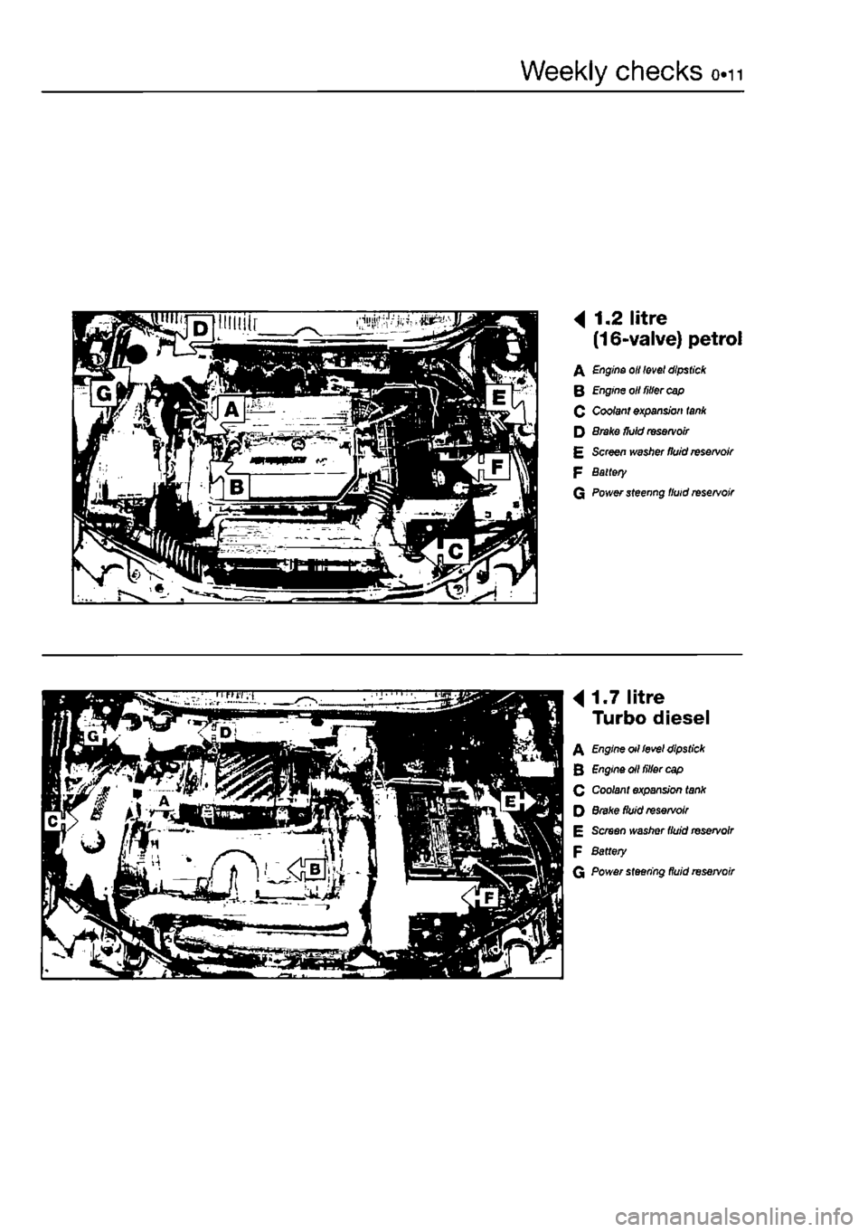
4 1.2 litre (16-valve) petrol
A Engine oil level dipstick
B Engine oil fitter cap 0 Coolant expansion tank D 8rake fluid reservoir £ Screen ivasfter fluid reservoir P Battery G Power steenng fluid reservoir
B
4
1.7 litre Turbo diesel
A Engine otl level dipstick B Engine oil filler cap Q Coolant expansion tank Q Brake fluid reservoir E Screen washer fluid reservoir F Battery
G Power steering fluid reservoir
Page 84 of 225

2C*2 Diesel engine in-car repair procedures
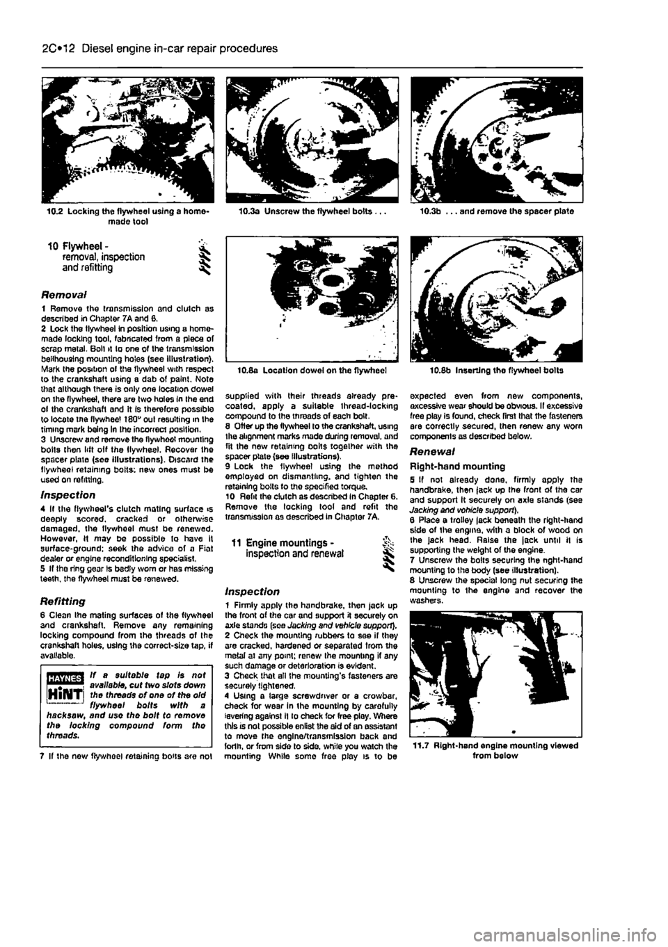
10.2 Locking the flywheel using a homo* made tool
10 Flywheel - £ removal, inspection § and refitting ^
Removal 1 Remove the transmission and clutch as described in Chapter 7A and 6, 2 Lock the tlywheei in position using a home-made locking tool, fabricated from a piece of scrap metal. Boll it to one of the transmission belihousing mounting holes (see illustration). Mark the position of the flywheel with respect to the crankshaft using a dab of paint. Note that although there is only one location dowel on the flywheel, there are two holes In the end ol the crankshaft and it Is therefore possible to locate tne flywheel 180v out resulting in the timing mark being In Ihe incorrect position. 3 Unscrew and remove the flywheol mounting bolts then lift olf the llywheel. Recover the spacer piate (see illustrations). Discard the flywheol retaining bolts: new ones must be used on refitting,
Inspection 4 If the flywheel's clutch mating surface >s deeply scored, cracked or otherwise damaged, the flywhoel must be renewed. However, H may be possible to have It surface-ground: seek the advice of a Fiat dealer or engine reconditioning specialist, 5 If the ring gear Is bsdly worn or has missing teeth, the flywheel must be renewed.
Refitting 6 Clean the mating surfaces of the flywheel and crankshaft. Remove any remaining locking compound from the threads of the crankshaft holes, using the correct-size tap, if available.
HBTiffSrl If a suitable tap Is not
Wijlilfil
available, cut two slots down HlNTi threads of one of the old 1 J flywheel bolts with a hacksaw, and use the bolt to removo the locking compound form tho threads.
7 If the now flywheel retaining bous are not
10.8a Location dowel on the flywheel
supplied with their threads already pre* coated, apply a suitable thread-locking compound to the threads of each bolt. 8 Otter up the flywheel to the crankshaft, using the abgnment marks made during removal, and fit the new retaining oolts together with the spacer plate (see Illustrations). 9 Lock the flywheel using Ihe method employed on dismantling, and tighten the retaining bolts to the specified torque. 10 Refit the clutch as described in Chapter 6. Remove the locking tool and refit the transmission as described in Chapter 7A,
11 Engine mountings -inspection and renewal
Inspection 1 Firmly apply the handbrake, then jack up the front of the car and support it securely on axle stands (see Jacking and vehicle support). 2 Check the mounting rubbers to see if they are cracked, hardened or separated from the metal ai any point; renew Ihe mounting if any such damage or deterioration is evident. 3 Check that all the mounting's fasteners are securely tightened, 4 Using a large screwdriver or a crowbar, check for wear In the mounting by carefully levering against il to check for free ploy. Where this is not possible enlist the aid of an assistant to move the onglno/transmission back and forlh. or from side lo side, while you watch the mounting While some free play is to be
10.8b Inserting tho flywheel bolts
expected even from new components, axcessive wear should be obvious. II excessive free play Is found, check first that the fasteners are correctly secured, then renew any worn components as described below.
Renewal Right-hand mounting 5 If not already done, firmly apply the handbrake, then jack up the front ot tho car and support it securely on axle stands (see Jacking and vohicle support), 6 Place a trolley lack beneath the right-hand side of the engine, with a block of wood on Ihe jack head. Raise the jack until it is supporting the weight of the engine. 7 Unscrew the bolts securing the nght-hand mounting to the body (see illustration). 8 Unscrew the special long nut securing the mounting to Ihe engine and recover the washers.
11.7 Right-hand engine mounting viewed from below
Page 148 of 225

5A»1
Chapters Part A:
Starting and charging systems
Contents
Alternator - brush holder/regulator module renewal 6 Alternator/charging system • testing in vehicle 4 Alternator • removal and refitting 5 Auxiliary drivebelt • removal, refitting and adjustment See Chapter 1A or 1B Battery • condition check See Weekly Checks Battery • removal and refitting 3
Battery - testing and charging 2 Electrical fault finding • general Information See Chapter 12 General Information and precautions 1 Starter motor • removal and refitting 8 Starter motor - testing and overhaul 9 Starting system - testing 7
Degrees of difficulty
Easy, suitable for & novice with Tittle jg experience ^
Fairly easy, suitable ^ for beginner with some experience 3J
Fairly tfifftait, J^ sutable for competent ^ DIYmechanic ^
Difficult, suitable for ^ experienced D!Y mechanic ^
Verydtfficult, jk stitable far expert DfY X or professional ^
Specifications
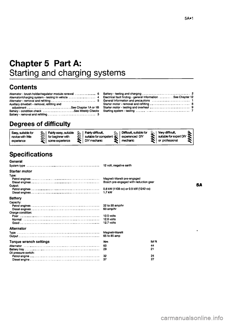
General System type 12 volt, negative earth
Starter motor Type: Petrol engines Magneti-Marelli pre-engaged Diesel engines Bosch pre-engaged with reduction gear Output: 5A Petrol engines 0.8 kW (1108 cc) or 0.9 kW (1242 cc) Diesel engines 1.7 kW
Battery Capacity: Petrol engines 32 to 50 amp/hr Diesel engines 60 amp/hr Charge condition: Poor 12.5 volts Normal 12.6 volts Good 12.7 volts
Alternator Type Magneti-Marelli Output 65 to 85 amp
Torque wrench settings Nm ibt ft Alternator 60 44 Battery tray 29 21 Oil pressure switch: Petrol engine 32 24 Diesel engine 37 27