Rear drum FIAT PUNTO 1995 176 / 1.G Workshop Manual
[x] Cancel search | Manufacturer: FIAT, Model Year: 1995, Model line: PUNTO, Model: FIAT PUNTO 1995 176 / 1.GPages: 225, PDF Size: 18.54 MB
Page 34 of 225
Maintenance procedures - petrol models 1A.15
Every 40 000 miles (60 000 km) or 4 years
29 Rear brake shoe check
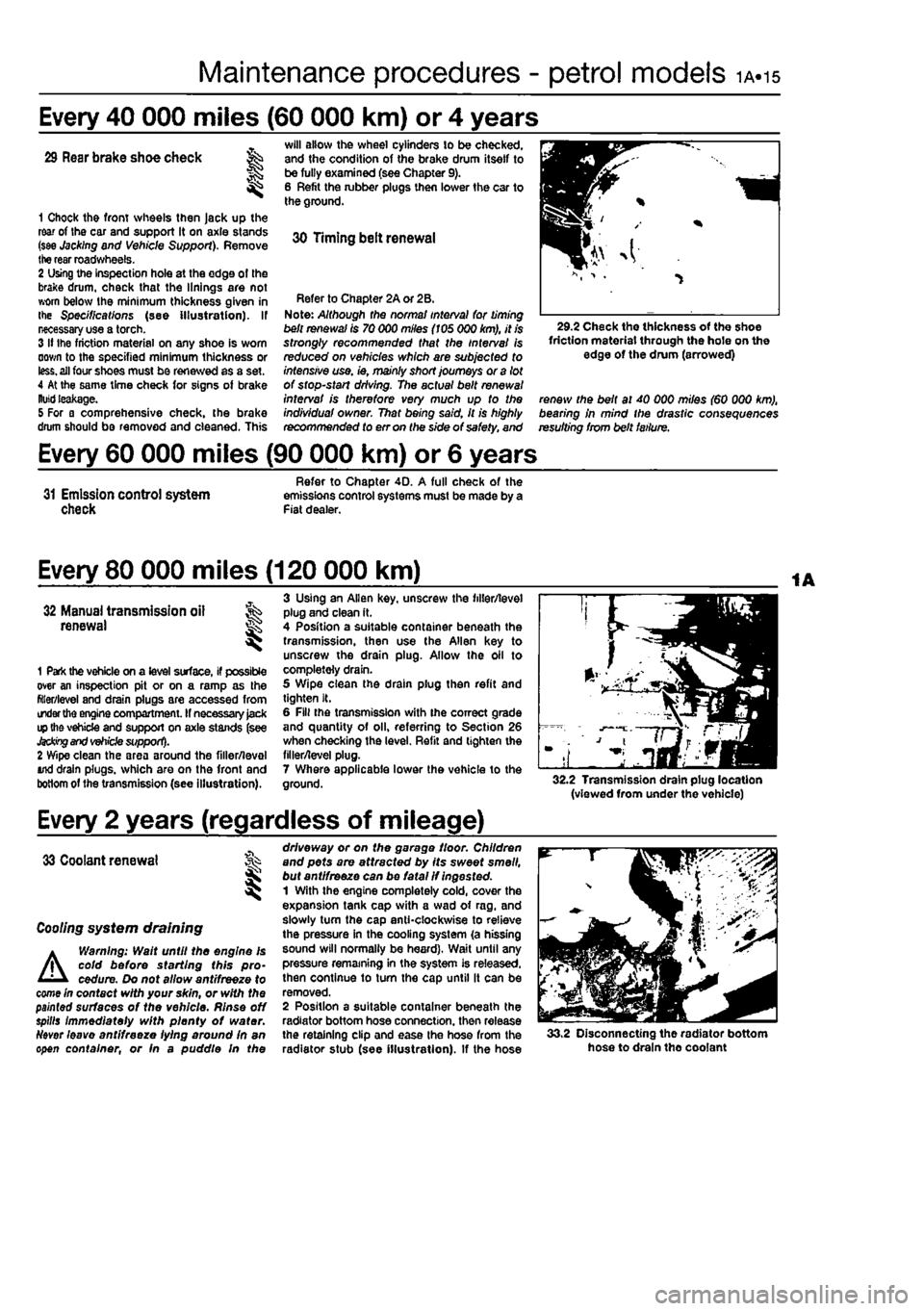
1 Chock the front wheels then Jack up the rear of Ihe car and support it on axle stands (see Jacking and Vehicle Support). Remove the rear roadwheels. 2 Using the inspection hole at the edge of the brake drum, check that the linings are not worn below Ihe minimum thickness given in the Specifications (see illustration). If necessary use a torch. 3 If the friction material on any shoe is worn down to the specified minimum thickness or
less,
all four shoes must be renewed as a set. 4 At the same time check for signs of brake
Kutti
leakage. 5 For a comprehensive check, the brake drum should be removed and cleaned. This
will allow the wheel cylinders to be checked, and the condition of the brake drum itself to be fully examined (see Chapter 9). 6 Refit the lubber plugs then lower the car to the ground.
30 Timing belt renewal
Refer to Chapter 2A or 2B. Note: Although the norma/ interval for timing belt renewal is 70 000 miles (105 000 km), it is strongly recommended that the interval Is reduced on vehicles which are subjected to intensive use. ie, mainly short journeys or a lot of stop-start driving. The actual belt renewal interval is therefore very much up to the individuaf owner. That being said, it is highly recommended to err on the side of safety, and
29.2 Check the thickness of the shoe friction material through the hole on the edge of the drum (arrowed)
renew the belt at 40 000 miles (60 000 km), bearing in mind the drastic consequences resulting from belt failure.
Every 60 000 miles (90 000 km) or 6 years
31 Emission control system check
Refer to Chapter 4D. A full check of the emissions control systems must be made by a Fiat dealer.
Every 80 000 miles (120 000 km)
32 Manual transmission all renewal S
1 Park the vehicle on a level surface, if possible over an inspection pit or on a ramp as the filler/level and drain plugs are accessed from order
the
engine compartment. If necessary
Jack
ip the vehicle and support on axle stands (see
Jacking and vehicle
support). 2 Wipe clean the area around the filler/leval And drain plugs, which are on the front and bottom of the transmission (see illustration).
3 Using an Allen key. unscrew the filler/level plug and clean it. 4 Position a suitable container beneath the transmission, then use the Allen key to unscrew the drain plug. Allow the oil to completely drain. 5 Wipe clean the drain plug then refit and tighten It. 6 Fill the transmission with ihe correct grade and quantity of oil, referring to Section 26 when checking the level. Refit and lighten the filler/level plug. 7 Where applicable lower the vehicle to the ground. 32.2 Transmission drain plug location (viewed from under the vehicle)
Every 2 years (regardless of mileage)
33 Coolant renewal
I
Cooling system draining
A
Warning: Walt until the engine Is cold before starting this pro-cedure. Do not allow antifreeze to come In contact with your skin, or with the painted surfaces of the vehicle. Rinse off spills immediately with plenty of water.
Ndver
leave antifreeze lying around In an open container, or fn a puddle In the
driveway or on the garage floor. Children and pets are attracted by its sweet smell, but ant/freeze can be fatal if ingested. 1 With the engine completely cold, cover the expansion tank cap with a wad of rag. and slowly turn the cap anticlockwise to relieve the pressure in the cooling system (a hissing sound will normally be heard). Wait until any pressure remaining in the system is released, then continue to tum the cap until it can be removed. 2 Position a suitable container beneath the radiator bottom hose connection, then release the retaining clip and ease the hose from the radiator stub (see illustration). If the hose 33.2 Disconnecting the radiator bottom hose to drain tho coolant
Page 48 of 225
1B«12 Every 20 000 miles - diesel models
21 Road test
Instruments and electrical equipment 1 Check the operation of atl instruments and electrical equipment. 2 Make sure that all instruments read correctly, and switch on all electrical equipment rn turn, to check that It functions properly. Steering and suspension 3 Check for any abnormalities in the steering, suspension, handling or road feel. 4 Drive the vehicle, and check that there are no unusual vibrations or noises. 5 Check that the steering feete positive, with no excessive sloppiness, or roughness, and check for any suspension noises when cornering and driving over bumps. Drivetrain 6 Check (he performance of the engine, clutch, transmission and driveshafts.
7 Listen for any unusual noises from the engine, clutch and transmission. 8 Make sure that the engine runs smoothly when Idling, and that there is no hesitation when accelerating. 9 Check that the clutch action is smooth and progressive, that tho drive is taken up smoothly, and that the pedal travel Is not excessive. Also listen for any noises when the clutch pedal is depressed. 10 Check that all gears can be engaged smoothly without noise, and that the gear lever action Is not abnormally vague or notchy. 11 Listen for a metallic clicking sound from ihe front of the vehicle, as the vehicle « driven slowly In a circle with the steering on full-lock. Carry out this check In both directions, if a clicking noise is heard, this Indicates wear in a driveshaft |oinl, in which case renew the joint if necessary.
Check the braking system 12 Make sure that the vehicle does not pull to one side when braking, and that the wheels do not lock prematurely when braking hard.
13 Check that there Is no vibration through the steering when braking. 14 Check that the handbrake operates correctiy without excessive movement of th« lever, end that it holds the vehicle stationery on a slope. 15 Test the operation of the brake servo unit as follows. With the engine off, depress the footbrake four or five times to exhaust the vacuum. Hold the brake pedal depressed, then start the engine. As the engine starts, there should be a noticeable give In the brake pedal as vacuum builds up. Allow the engine to run for at least two minutes, and then switch it off. If the brake pedal is depressed now, it should be possible to detect a hiss from the servo es the pedal is depressed. After about four or five applications, no fimher hissing should be heard, and the pedal should feel considerably harder. Note: The vacuum for the servo unit is provided by the vacuum pump mounted on the left-hand end of t/ie cylinder head.
Every 30 000 miles (45 000 km) or 3 years
22 Manual transmission oil level check ;5§
1 Park the vehicle on a level surface. If possible over an inspection pit or on a ramp as the filler/level plug is best reached from under Ihe engine compartment. The oil level must be checked before the car Is driven, or at least 5 minutes after the engine has been switched off. If the oil is checked Immediately after driving the car. some of the oil will remain distnbuted around the transmission compo-nents, resulting In an inaccurate level reading. 2 Wipe clean the area around the filler/level plug, which is situated on tho front of the
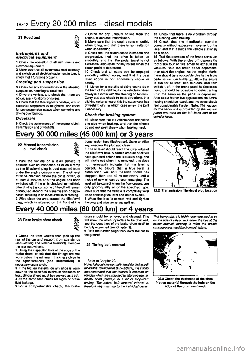
transmission (see illustration). Using an Allen key. unscrew the plug and clean it. 3 The oil level should reach the lower edge of the filler/level hole. A certain amount of oil will have gathered behind the filler/level plug, and will trickle out when it is removed; this does not necessarily Indicate that the level Is correct. To ensure that a true level Is established, wait until the Initial trickle has stopped, then add oil as necessary until a trickle of new oil can be seen emerging. The level will be correct when the flow ceases; use only good-quality oil of the specified type-Make sure that the vehicle Is completely level when checking the level and do not overfill. 4 When the level is correct refit and tighten the plug and wipe away any spilt oil.
22.2 Transmission filler/level plug location
Every 40 000 miles (60 000 km) or 4 years
23 Rear brake shoe check
1 Chock the front wheels then jack up the rear of the car and support It on axle stands (see Jacking and Vehicle Support), Remove the rear roadwhecla. 2 Using the inspection hole at the edge ot the brake drum, check that the linings are not worn below the minimum thickness given In the Spec ifi cat Ions (see Illustration). If necessary use a torch. 3 If the friction material on any shoe is worn down to the specified minimum thickness or iess. all four shoes must be renewed as a set, 4 At the same time check for signs of brake fluid leakage. 5 For a comprehensive check, the brake
drum should be removed and cleaned. This will allow the wheel cylinders to be checked, and the condition of the brake drum itself to be fully examined (see Chapter 9). 8 Refit the rubber plugs then lower the car to the ground.
24 Timing belt renewal
Refer to Chapter 2C. Note: Although the normal interval for timing belt
ranees/a!
is 70 000
mHes
(105 000
km),
it is strong recommended that the interval is reduced on vehicles which are subjected to intensive use, ie, mainly short journeys or a lot of stop-start driving. The actual belt renewal interval is therefore very much up to tho individual owner.
That being said, it is highly recommended to err on the side of safety, and renew (he belt at
this
earlier interval, bearing in mind the drastic consequences resulting from belt fetfure.
23.2 Check the thickness of the shoe friction material through the hole on the edge of the drum (arrowed)
Page 177 of 225
9«1
Chapter 9
Braking system
Contents
Brake disc - inspection, removal and refitting 4 Brake fluid level check See Weekly checks Brake fluid renewal See Chapter 1A or 1B Brake warning lamp check See Chapter 1A or 1B Front brake caliper - removal, overhaul and refitting 3 Front brake pad check See Chapter 1A or 1B Front brake pads - renewal 2 General information 1 Handbrake - checking and adjustment 9
Handbrake cables - removal and refitting 10 Hydraulic pipes end hoses - renewal 13 Hydraulic system - bleeding 11 Master cylinder - removal and refitting 12 Roar brake shoe check See Chapter 1A or 1B Rear brake shoes - renewal 5 Rear brake drums - removal, inspection and refitting 6 Rear wheel cylinder - removal, overhaul and refitting 7 Stop-light switch - adjustment, removal and refitting 6
Degrees of difficulty
Easy, suitable
far
novice with Sttle
experience ^
Fairly
easy,
suitable ^ (orbeginnerwith ®
some
experience
Fairly difficult, suitable
for
compe«ent ^ CHYmechanlc ^
Difficult, suitable for
experienced DIY « mechanic ^
Very difficult, ^
suitable
for
expert DIY
or professional ^
Specifications
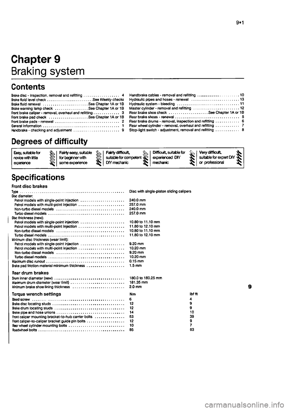
Front disc brakes Type Disc with single-piston sliding calipers Disc diameter Petrol models with single-point Injection 240.0 mm Petrol models with multi-point Injection 257.0 mm Non-turbo diesel models 240.0 mm Turbodieselmodels 257.0 mm Disc thickness (new); Petrol models with single-point injection 10.80 to 11.10 mm Petrol models with multi-point Injection 11.80 to 12.10 mm Non-turbo diesel models 10.80 to 11.10 mm Turbodieselmodels 11.80 to 12.10 mm Minimum disc thickness (wear limit): Petrol models with single-pant Injection 9.20 mm Petrol models with multi-point Injection 10.20 mm Non-turbo diesel models 9.20 mm Turbo diesel models 10.20 mm Maximum disc runout 0.15 mm Brake pad friction material minimum thickness 1.5 mm
Rear drum brakes Drum Inner diameter (new) 180.0 to 180.25 mm Maximum drum diameter (wear limit) 181.35 mm Minimum brake shoe lining thickness 2.0 mm
Torque wrench settings Nm ibf ft
Bfeed
screw 6 4 Brake disc locating studs 12 9 Brake drum locating studs 12 9 Brake pipe and hose unions 14 10 Front caliper mounting bracket-to-hub carrier bolts 53 39 Front caliper-to-caliper bracket guide pin bolts 12 9 fleer wheel cylinder mounting boils 10 7 Roadwheel bolts 85 63
Page 178 of 225
9*2 Braking system
2.3a Release tho locking clip ...
1 General information
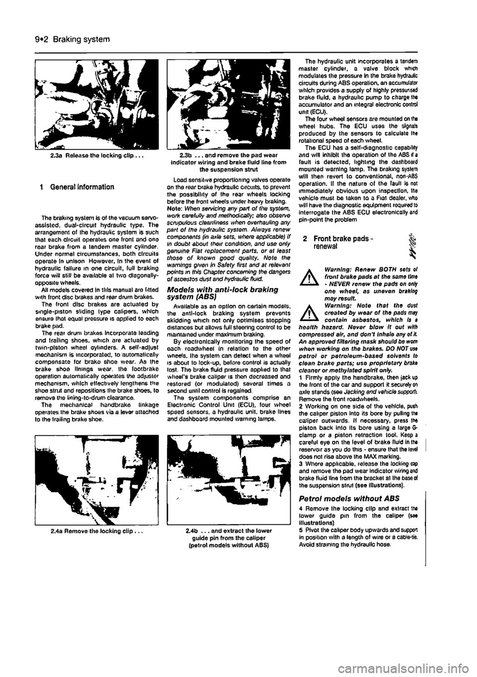
The braking system is of the vacuum servo-assisted. dual-circuit hydraulic type. The arrangement of Ihe hydraulic system is such that each circuit operates one front ond ono rear brake from a tandem master cylinder. Under normal circumstances, both circuits operate In unison However, in the event of hydraulic failure in one circuit, lull braking force will still be available at two diagonally-opposite wheels. All models covered in this manual are fitted with front disc brakes and rear drum brakes. The front disc brakes are aotuated by single-piston sliding lype calipers, which ensure lhat equal pressure is applied to each brake pad. The rear drum brakes incorporate leading and trailing shoes, which are actuated by twin-piston wheel cylinders. A self-adjust mechanism is incorporated, to automatically compensate for brako shoe wear. As the brake shoe linings wear, the footbrnke operation automatically operates the adjuster mechanism, which effectively lengthens the shoe strut and repositions the brake shoes, to remove the llning-to-drum clearance. The mechanical handbrake linkage operates the brake shoos via a lever attached to the trailing brake shoe.
2.3b ... and remove the pad wear indicator wiring and brake fluid line from the suspension strut Load sensitive proportioning valves operate on the rear brake hydraulic circuits, to prevent the possibility of the rear wheels locking before the front wheels under heavy braking. Note: When servicing any part of the system, work carefully and methodically; also observe scmpulous cleanliness when overhauling any part of the hydraulic sysiem. Always renew components (in axle sets, where applicable) if In doubt about their condition, and use only genuine Fiat replacement parts, or at least those of known good quality. Note the warnings given in Safety first and at relevant points in this Chapter concerning fhe dangers of asoestos dust and hydraulic fluid.
Models with anti-lock braking system (ABS) Available as an option on certain models, the anti-lock braking system prevents skidding which not only optimises stopping distances but allows full steering control to be maintained under maximum braking. By electronically monitoring the speed of each roadwheel in relation to the other wneete, Ihe system can detect when a wheel is about to lock-up, before control is actually lost. The brake fluid pressure applied to that wheel's brake caliper is then decreased and restored (or modulated) several times a second until control
£s
regained. The system components comprise an Electronic Control Unit (ECU), four wheel speed sensors, a hydraulic unit, brake lines and dashboard mounted warning lamps.
The hydraulic unit incorporates a tandem master cylinder, a valve block which modulates the pressure in the brake hydrauli: circuits during ABS operation, an accumulator which provides a supply of highly pressursed brake fluid, a hydraulic pump to charge Ihe accumulator and an integral electronic control unit (ECU). The four wheel sensors are mounted on the wheel hubs. The ECU uses the signals produced by the sensors to calculate Ihe rotational speed of each wheel, The ECU has a self-diagnostic capability and will inhibit the operation of the ABS il a fault is detected, lighting the dashboard mounted warning lamp. The braking system will then revert lo conventional. non-ABS operation. II the nature of the laull ie not immediately obvious upon inspection, the vehicle must be taken to a Fiat dealer, who will have the diagnostic equipment
required
lo interrogate the ABS ECU electronically and pin-point the problem
2 Front brake pads - & renewal S
A
Warning: Renew BOTH sets ol front brake pads at the same
time
- NEVER renew the pads on
only
one wheel, as uneven braking may result
A
Warning: Note that the dust created by wear of the pads
may
contain asbestos, which is a health hazard. Never blow It out with compressed air, and don't inhale any of
it.
An approved filtering mask should be worn when working on the brakes. DO NOT use petrol or petroleum-based solvents to clean brake parts; use proprietary braks cleaner or methylated spirit only. 1 Firmly apply the handbrake, then jack up the front of the car and support it securely
on
axle stands (see Jacking and vehicle supporti. Remove the front roadwheeis. 2 Wording on one side of the vehicle, puth the caliper piston into its bore by pulling the caliper outwards. If necessary, press the piston back into its bore using a large G-clamp or a piston retraction tool. Keep a careful eye on the level of brake llufd in Ihe I reservoir as you do this - ensure that the
level
I does not rise above the MAX marking. 3 Whore applicable, release the locking dp and remove the pad wear indicator
wiring end
brake fluid line from the bracket at Ihe
base of
the suspension strut (see illustrations).
Petrol models without ABS 4 Remove the locking clip and exlracl the lower guide pin from the caliper (see illustrations) 5 Pivot the caliper body upwards and support In position with a length of wire or a cabie-fc. Avoid straining the hydraulic hose.
2,4a Remove the locking clip ... 2.4b ... and extract the lower guide pin from the caliper (petrol models without ABS)
Page 182 of 225
9*6 Braking system
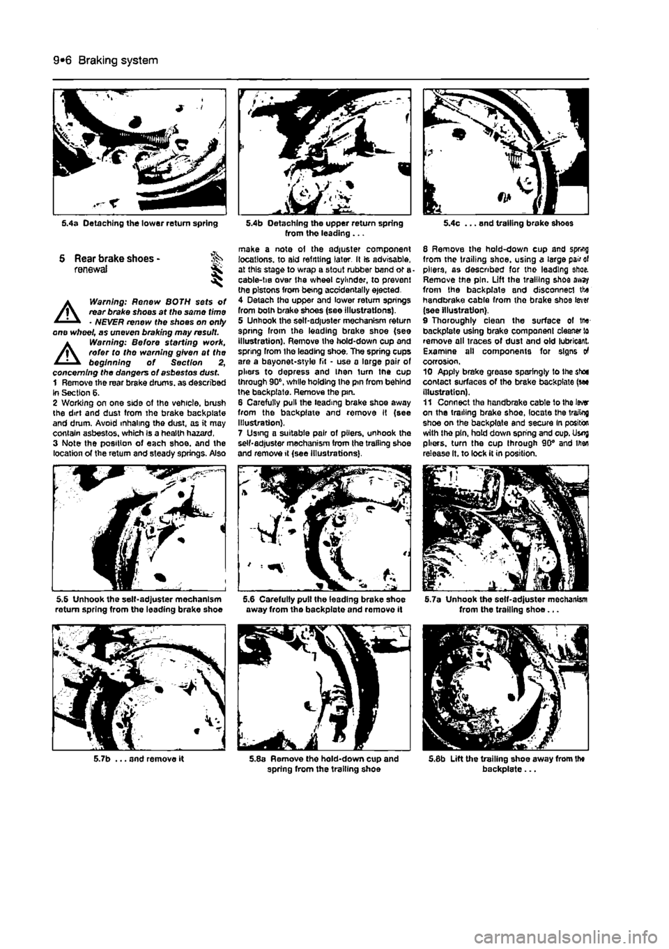
5.4a Detaching the tower return spring
S Rear brake shoes -renewal ji,
A
Warning: Renew BOTH sets of rear brake shoos at the same time • NEVER renew the shoes on onty one wheel, as uneven braking may result.
A
Warning: Before sterling work, refer to tho warning given at the beginning of Section 2, concerning the dangers of asbestos dust. 1 Remove the rear brake drums, as described In Section 6. 2 Working on one side ot the vehicle, brush the dirt and dust tram tho brake backpiate and drum. Avoid inhaling the dust, as it may contain asbestos, which Is a health hazard, 3 Note the position of each shoe, and the location of the return and steady springs. Also
5.6 Unhook the self-adjuster mechanism roturn spring from the leading brake shoe
5.7b ... and remove it
5.4b Detaching the upper return spring from tho leading ...
make a note oi the adjuster component locations, to aid refitting later. Il is advisable, at this stage to wrap a stout rubber band or a cable-tie over Ihe wheel cylinder, to prevent the pistons from being accidentally ejected. 4 Detach tha upper and lower return springs from both brake shoes (see illustrations). 5 Unhook the sell-adjuster mechanism return spring Iroin the leading brake shoe (see illustration). Remove the hold-down cup and spring from the leading shoe. The spring cups are a bayonet-style fit • use a large pair of pliers to depress and Ihen turn the cup through 90", while holding Ihe pin from behind the backpiate. Remove the pin. 6 Carefully pull the leading brake shoe away from the backpfaie and remove It (see Illustration). 7 Using a suitable pair of pliers, unhook the self-adjuster mechanism from the trailing shoe and remove it (see Illustrations).
away from the backpiate and remove it
5.8a Remove the hold-down cup and spring from the trailing shoe
5.4c ... and trailing brake shoes
8 Remove the hold-down cup and spring from the trailing shoe, using a large pair of pliers, as described for the leading shoe. Remove the pin. Lift the trailing shoe away from the backpiate and disconnect the handbrake cable from the brake shoe lever (see illustration). 9 Thoroughly ciean the surface of tru-backpiate using brake component cleaner lo remove all traces of dust and old lubricant. Examine all components for signs o4 corrosion. 10 Apply brake grease sparingly to the shoe contact surfaces of tho brake backpiate (see Illustration). 11 Connect tha handbrake cable to the Iwr on the trailing brake shoe, locate the trailing shoe on the backpiate and secure In position with the pin, hold down spring and cup. Usnj pliers, turn the cup through 90" and men release It. to lock it in position.
5.7a Unhook the solf-adjuster mochanism from the trailing shoe...
5.6b Lift the trailing shoe away from the backpiate...
Page 183 of 225
Braking system 9®7
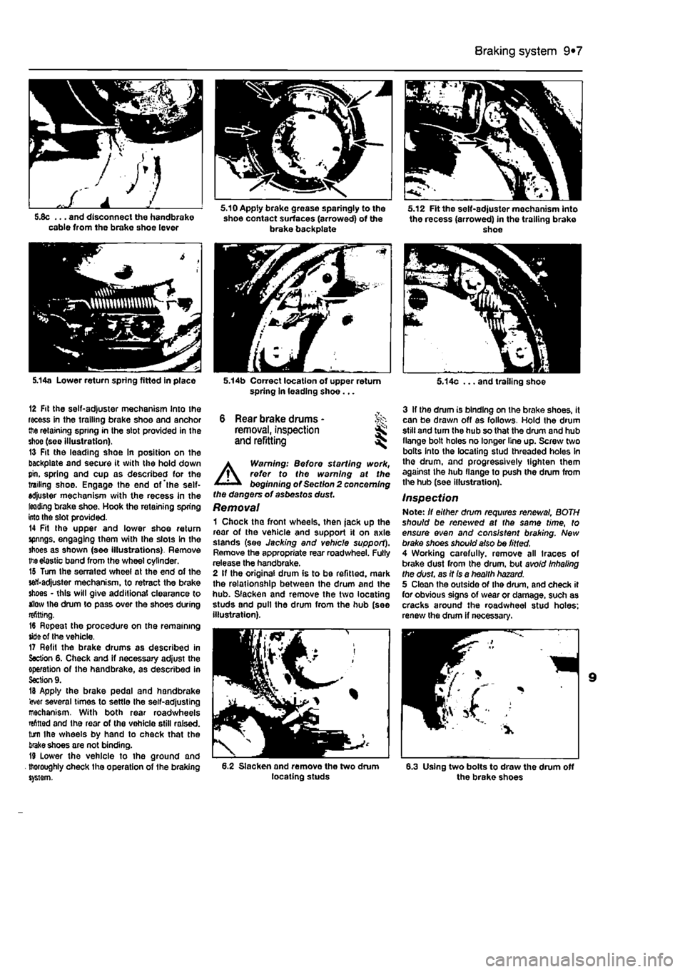
5JJc ... and disconnect the handbrake cable from the brake shoe lever
5.14a Lower return spring fitted in place
12 Fit the self-adjuster mechanism Into the recess in the trailing brake shoe and anchor the retaining spring in the slot provided in the shoe (see Illustration). 13 Fit the leading shoe In position on the backpiste and secure it with the hold down pin. spring and cup as described for the trailing shoe. Engage the end of'the self-adjuster mechanism with the recess In the leading brake shoe. Hook the retaining spring into the slot provided. 14 Fit the upper and lower shoe return spnngs. engaging them with the slots In the shoes as shown (see illustrations). Remove
me
elastic band from the wheel cylinder. 15 Turn Ihe serrated wheel at the end of the self-adjuster mechanism, to retract the brake shoes - this will give additional clearance to ilow Ihe drum to pass over the shoes during refitting. 16 Repeat the procedure on the remaining tide of the vehicle. 17 Refit the brake drums as described in Section 6. Check and if necessary adjust the operation of the handbrake, as described in Section 9. IB Apply the brake pedal and handbrake 'ever several times to settle the self-adjusting mechanism. With both rear roadwheels rsfitted and Ihe rear of the vehicle still raised, turn Ihe wheels by hand to check that the take shoes are not binding. 19 Lower the vehicle to the ground and thoroughly check the operation of the braking system.
5.10 Apply brake grease sparingly to the shoe contact surfaces (arrowed) of the brake backplate
5.14b Correct location of upper return spring In leading shoe...
6 Rear brake drums -removal, inspection and refitting ^
A
Warning: Before starting work, refer to the warning at the beginning of Section 2 concerning the dangers of asbestos dust Removal 1 Chock the front wheels, then jack up the roar of the vehicle and support it on axle stands (see Jacking and vehicle support). Remove the appropriate rear roadwheel. Fully release the handbrake. 2 If the original drum is to be refitted, mark the relationship between the drum and the hub. Slacken and remove the two locating studs and pull the drum from the hub (see illustration).
6.2 Slacken and remove the two drum locating studs
5.12 Fit the self-adjuster mechanism into the recess (arrowed) in the trailing brake shoe
5.14c ... and trailing shoe
3 If the drum is binding on Ihe brake shoes, it can be drawn off as follows. Hold the drum still and turn the hub so that the drum and hub flange bolt holes no longer line up. Screw two bofts into the locating stud threaded holes In tho drum, and progressively lighten them against the hub llange to push the drum from the hub (see illustration).
Inspection Note: If either drum requires renewal, BOTH should be renewed at the same time, to ensure even and consistent braking. New brake shoes should also be fitted. 4 Working carefully, remove all traces of brake dust from the drum, but avoid Inhaling the dust, as it is a health hazard. 5 Clean the outside of the drum, and check it for obvious signs of wear or damage, such as cracks around the roadwheel stud holes; renew the drum if necessary.
6.3 Using two bolts to draw the drum off the brake shoes
Page 184 of 225
9*8 Braking system
6 Carefully examine the Inside of tho drum. Light scoring of the friction surface is normal, but if heavy scoring Is found, the drum must be renewed. 7 It is usual to find a lip on the dmm's inboard edge which consists of a mixture of rust and brake dust: this should be carefully scraped away, to leave a smooth surface which can be polished with fine (120 to 150-grade) emery paper. If, however, the tip is due to the friction surface being recessed by excessive wear, then the drum must be renewed. 6 If the drum Is thought to be excessively worn, or oval, its internal diameter must be measured at several points using an internal micrometer. Take measurements In pairs, the second at right-angles to the first, and compare the two, to check for signs of ovality. Provided that it does not enlarge the dium to beyond the specified maximum diameter, it may be possible to have the drum refinished by skimming or grinding; if this is not possible, Ihe drums on both sides must be renewed. Note that if the drum is to be skimmed, BOTH drums must be refinished. to maintain a consistent Internal diameter on both sides.
Refitting 9 II a new brake drum is to be Installed, use a suitable solvent to remove any preservative coating thai may have been applied to its internal fnction surfaces. Note that it may also be necessary to shorten the adjuster strut length, by rotating the sedated strut wheel, lo allow Ihe drum lo poss over the brake shoes • see Section S for details. 10 II tho original dfum is being refitted, align the marks made on the drum and hub before removal, then lit the drum over the hub. Refit the locating studs and tighten them to the specified torque. 11 Depress the footbrake repeatedly to expand the brake shoes against the drum, and ensure that normal pedal pressure Is restored. 12 Check and if necessary adjust the handbrake cable as described In Section 9. 13 Refit tho roadwheels, and lower the vehicle to the ground.
7 Rear wheel cylinder -removal, overhaul and refitting jS
A
Warning: Before starting work, refer to the warnings at tho beginning of Sections 2 and 11 concerning the dangers ot handling asbestos dust and hydraulic fluid.
Removal 1 Remove the brake drum fsee Section 6). 2 Remove the brake shoes (see Section 5). 3 To minimise fluid loss during the following operations, remove the master cylinder reservoir cap. then tighten it down onto a piece of polythene, lo obtain an airtight seal.
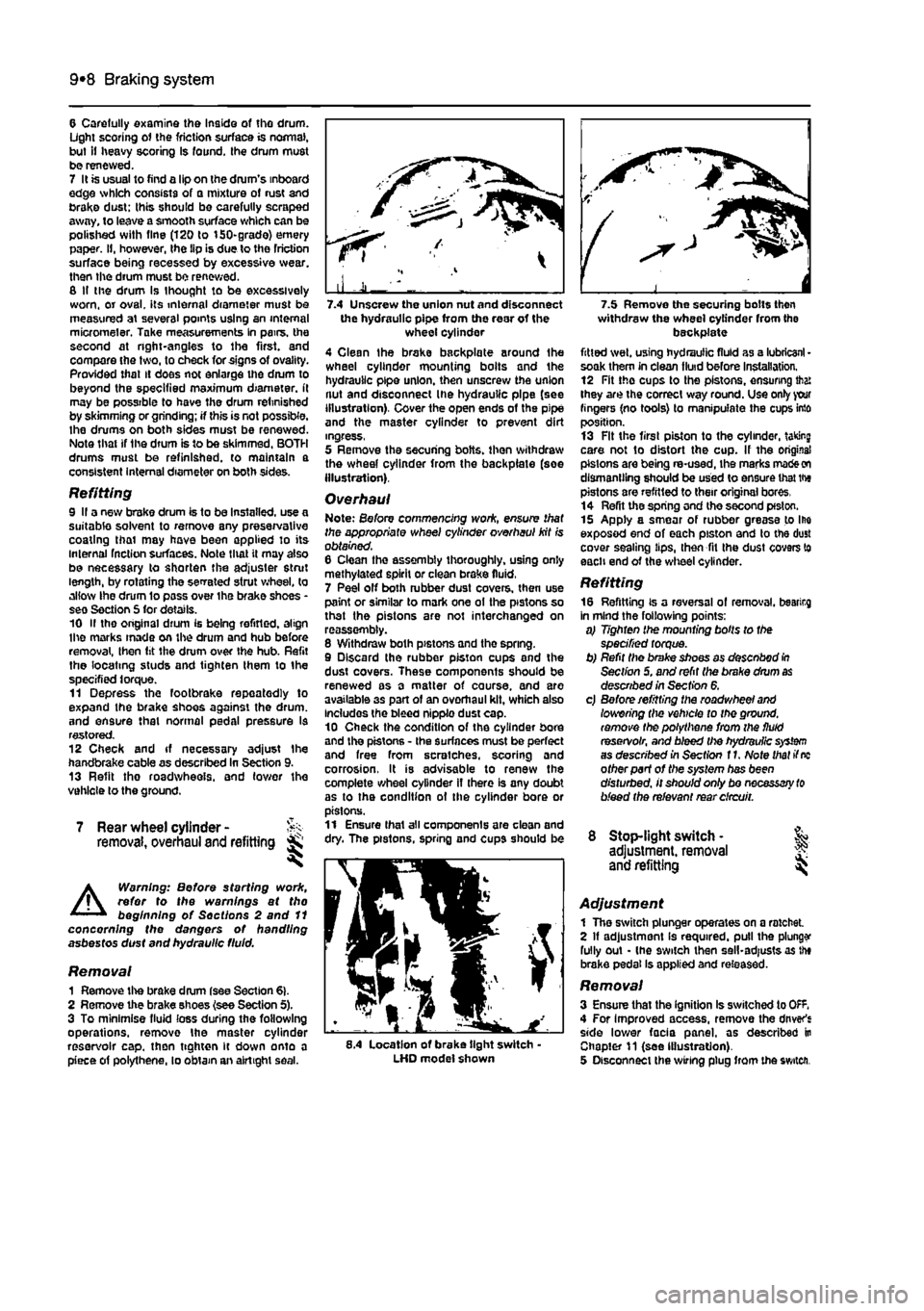
the hydraulic pipe from the rear of the wheel cylinder 4 Clean the brake backplate around Ihe wheel cylinder mounting boits and the hydraulic pipe union, then unscrew the union nut and disconnect Ihe hydraulic pipe (see illustration). Cover the open ends of the pipe and the master cylinder to prevent dirt ingress, 5 Remove the securing bolts, then withdraw the wheel cylinder from the backplate (soe Illustration).
Overhaul Note: Before commencing woric, ensure that the appropriate wheel cylinder overhaul kit is obtained. 6 Clean tho assembly thoroughly, using only methylated spirit or clean brake fluid, 7 Peel off both rubber dust covers, then use paint or similar to mark one ot the pistons so that the pistons are not interchanged on reassembly. 8 Withdraw both pistons and tho spring. 9 Discard the rubber piston cups and the dust covers. These components should be renewed as a matter of course, and are available 3s part of an overhaul kit, which also Includes the bleed nipple dust cap. 10 Check the condition of the cylinder bore and the pistons - the surfaces must be perfect and free from scratches, scoring and corrosion, It is advisable to renew the complete wheel cylinder if there is any doubt as to the condition ot the cylinder bore or pistons. 11 Ensure thai all components are clean and dry. The pistons, spring and cups should be
8.4 Location of brake tight switch-LHD model shown
withdraw the wheel cylinder from the backplate fitted wet, using hydraulic fluid as a lubricant • soak them in clean fluid before installation. 12 Fit the cups to the pistons, ensuring that they are the correct way round. Use only your fingers (no tools) to manipulate the cups into position. 13 Fit the first piston to the cylinder, taking care not to distort the cup. If the original pistons are being re-used, ihe marks
made on
dismantling should be used to ensure that the pistons are refitted to their original bores, 14 Refit the spring and the second pfston. 15 Apply a smear of rubber grease to Ihe exposed end of each piston and to the dust cover sealing lips, then fit Ihe dust covers to each end of the wheel cylinder.
Refitting 16 Refitting is a reversal of removal, bearirg in mind the following points: a) Tighten the mounting bolts to the specified torque. b) Refit the brake shoes as desenbod
In
Section 5. and refit the brake drum
as
described in Section 6. c) Before refitting the roadwheel
and
lowering the vehicle to the ground, remove the polythene from the fluid reservoir, and bleed the hydraulic
system
as described in Section f
1.
Note that if
nc
other part of the system has been disturbed, it should only bo necessary
to
bleed the relevant rear circuit.
8 Stop-light switch • & adjustment, removal J? and refitting
Adjustment 1 The switch plunger operates on a ratchet 2 If adjustment Is required, pull the plunge fully out - (he 9witch then sell-adjusts as the brake pedal Is applied and released.
Removal 3 Ensure that the ignition Is switched to OfF. 4 For Improved access, remove the driver's side lower facia panel, as described in Chapter 11 (see Illustration). 5 Disconnect the wiring plug from the switch.
Page 195 of 225
Suspension and steering
10*195
5 Front suspension >,•> tower arm balljoint -renewal ^
The balljoint is integral with the suspension ower arm (see Illustration). If the balljoint is worn or damaged, the complete lower arm oust be renewed as described In Section 4.
6 Front suspension ^ anti-roll bar -
removal and refitting s^
Removal 1 Chock the rear wheels, apply the handbrake, then jack up the front of the vehicle and support securely on axle stands •we Jacking and vehicle support). If required, wove the relevant roadwheels. 2 Refer to the Chapter 4D and unbolt the hnt section of the exhaust pipe. 3 Unscrew the bolts securing the anti-roll bar mountings to the suspension lower arms on ether side of the vehicle. Similarly, unscrew
ine
bolts securing the anti-roll bar mountings lo the suspension sub-frame (refer to the Derations in Section 4). 4 lower the anti-roll bar away from the underside of the vehicle. 5 Inspect the rubber bushes for cracks or ietertoratlon, If renewal Is necessary, slide the dd bushes from the bar, and fit the now items, using soapy water as a lubricant. Do rot apply grease or oil as this will attack the •ifiber. 9 Check the anti-roll bar for signs of damage, war or serious corrosion. Refitting 7 Refitting Is a reversal of removal, bearing In
mnd
the following points: sj
D'rw
up the holes af the ends of the anti-roll bar with those on the suspension iov/erarm. til
Tighten
all fixings to the specified torque, but do not do this until the vehicle is resting on its roadwheels, and the suspension has been settled, or damage to the bushes may result.
7.5 Slacken and remove the rear hub nut
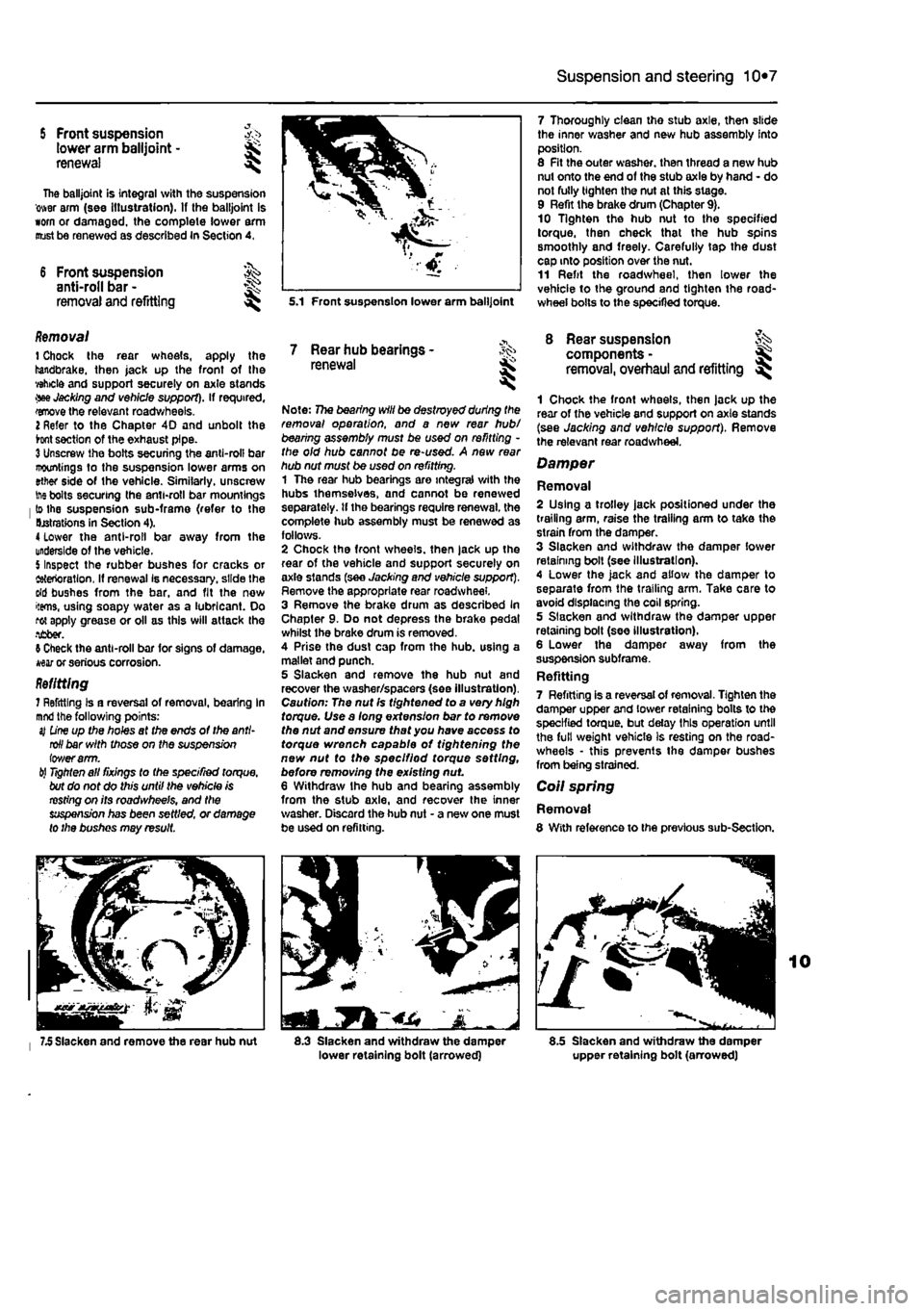
5.1 Front suspension lower arm balljoint
7 Rear hub bearings -renewal
Note: 77ie bearing will be destroyed during the removal operation, and a new rear hub/ bearing assembly must be used on refitting -the old hub cannot be re-used. A new rear hub nut must be used on refitting. 1 The rear hub bearings are integral with the hubs themselves, and cannot be renewed separately, tf the bearings require renewal, the complete hub assembly must be renewed as follows. 2 Chock the front wheels, then jack up the rear of the vehicle and support securely on axle slands (see Jacking and vehicle support). Remove the appropriate rear roadwheel. 3 Remove the brake drum as described In Chapter 9. Do not depress the brake pedal whilst the brake drum is removed. 4 Prise the dust cap from the hub. using a mallet and punch. 5 Slacken and remove the hub nut and recover the washer/spacers (see illustration). Caution: The nut Is tightened to a very high torque. Use a long extension bar to remove the nut and ensure that you have access to torque wrench capable of tightening the new nut to the speclfiod torque setting, before removing the existing nut 6 Withdraw Ihe hub and bearing assembly from the stub axle, and recover the inner washer. Discard the hub nut - a new one must be used on refitting.
1
8.3 Slacken and withdraw the damper lower retaining bolt (arrowed)
7 Thoroughly clean tho stub axle, then slide the inner washer and new hub assembly into position. 8 Fit the outer washer, then thread a new hub nut onto the end of the stub axle by hand - do not fully tighten the nut at this stage. 9 Refit the brake drum (Chapter 9). 10 Tighten the hub nut to the specified torque, then check that the hub spins smoothly and freely. Carefully tap the dust cap into position over the nut. 11 Refit the roadwheel, then lower the vehicle to the ground and tighten the road-wheel bolts to the specified torque.
8 Rear suspension components -removal, overhaul and refitting ^
1 Chock the front wheels, then jack up the rear of the vehicle and support on axle stands (see Jacking and vehicle support). Remove the relevant rear roadwheel.
Damper
Removal 2 Using a trolley jack positioned under the trailing arm, raise the trailing arm to take the strain from the damper. 3 Slacken and withdraw the damper lower retaining boll (see Illustration). 4 Lower the jack and allow the damper to separate from the trailing arm. Take care to avoid displacing the coil spring. 5 Slacken and withdraw the damper upper retaining bolt (see illustration). 6 Lower the damper away from the suspension subframe. Refitting 7 Refitting is a reversal of removal. Tighten the damper upper and lower retaining bolts to the specified torque, but delay this operation until the full weight vehicle is resting on the road-wheels • this prevents the damper bushes from being strained.
Coil spring
Removal 8 With reference to the previous sub-Section.
8.5 Slacken and withdraw the damper upper retaining bolt (arrowed)
Page 196 of 225
Suspension and steering 10*8
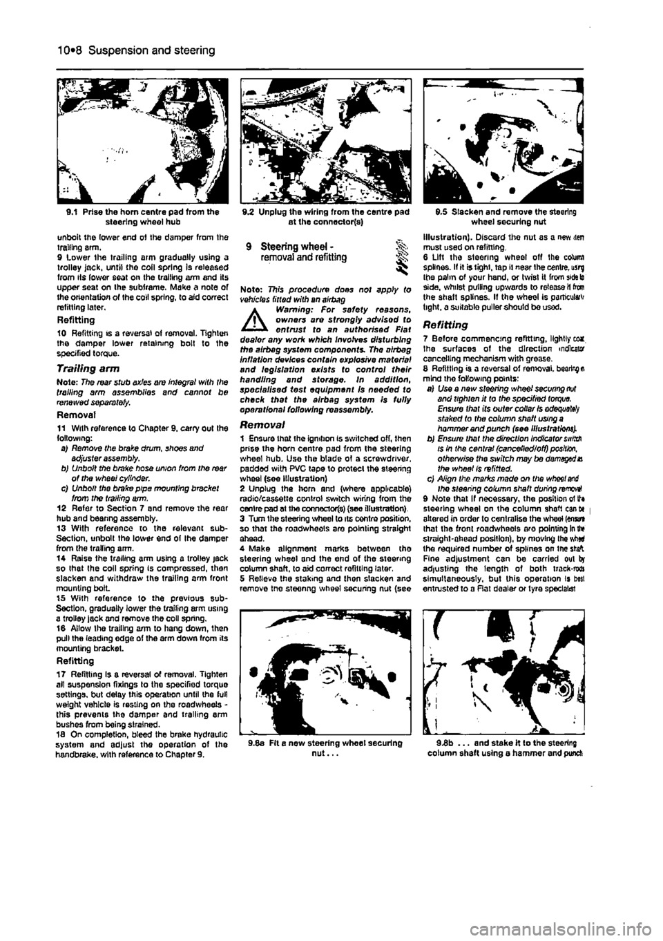
9.1 Prise the horn centre pad from the steering wheel hub unbolt the lower end of the damper from the trailing arm. 9 Lower the trailing arm gradually using a trolley jack, until the coil spring Is released from its lower seat on the trailing arm and its upper seat on the subframe. Make a note of the orientation of the coll spring, to aid correct refitting later. Refitting 10 Refitting is a reversal of removal, lighten the damper lower retaining bolt to the specified torque. Trailing arm Note: The rear stub axles are integral with the trailing arm assemblies and cannot be renewed separately. Removal 11 With reference to Chapter 9. carry out the following: a) Remove the brake drum, shoes and adjuster assembly. b) Unbolt the brake hose union from the
rear
of the wheel cylinder. c) Unbolt the brake pipe mounting bracket from the trailing arm. 12 Refer to Section 7 and remove The rear hub and beanng assembly. 13 With reference to the relevant sub-Section, unbolt the lower end of Ihe damper from the trailing arm. 14 Raise the trailing arm using a trolley jack so that the coll spring Is compressed, then slacken and withdraw the trailing arm front mounting bolL 15 With reference to the previous sub-Section, gradually lower the trailing arm using a trolley lack and remove the coll spring. 16 Allow Ihe trailing arm to hang down, then pull the leading edge of the arm down from its mounting bracket. Refitting 17 Refitting Is a reversal of removal. Tighten all suspension fixings to the specified torque settings, but delay this operation until the full weight vehicle is resting on the roadwheeis -this prevents the damper and trailing arm bushes from being strained. 18 On completion, bleed the brake hydraulic system and adjust the operation of the handbrake, with reference to Chapter 9.
9.2 Unplug the wiring from the centre pad at the connector(s)
9 Steering wheel - % removal and refitting ^
Note: This procedure does not apply to vehicles fitted with an airbag A Warning: For safety reasons, owners are strongly advisod to entrust to an authorised Fiat dealer any work which involves disturbing the airbeg system components. The airbag inflation devices contain explosive material and legislation exists to control their handling and storage. In addition, specialised test equipment Is needed to check thet the alrbag system Is fully operational following reassembly.
Removal 1 Ensure that the ignition is switched off, then prise the horn centre pad from the steering wheel hub. Use the blade of a screwdriver, padded with PVC tape to protect the steering wheel (see illustration) 2 Unplug the horn and (where applicable) radio/cassette control switch wiring from the centre pad at the connectors) (see illustration) 3 Turn the steering wheel to its centre position, so that the roadwheeis are pointing straight ahead. 4 Make alignment marks between the steering wheel and the end of the steering column shaft, to aid correct refitting later, 5 Relieve the staking and then slacken and remove tne steenng wheel securing nut (see
9.5 Slacken and remove the steering wheel securing nut Illustration). Discard the nut as a new item must used on refitting. 6 Lift the steering wheel off the column splines. If it is tight, tap il near the centre, usrg the palm of your hand, or twist it from
side to
side, whilst pulling upwards to release il ton the shaft splines. If the wheel is particular tight, a suitable puller should be used.
Refitting 7 Before commencing refitting, lightly eca. Ihe surfaces of the direction indicator cancelling mechanism with grease. 8 Refitting is a reversal of ren>oval.
bearing a
mind the following points: a) Use a new steering wheel
securing not
and tighten it to the specified
torque.
Ensure that its outer collar
Is adequate^
staked to the column shaft
using a
hammer and punch (see Illustrations). b) Ensure that the direction Indicator
swiith
is in the central (cancelled/off)
position,
otherv/ise the sivitch may be damaged X the wheel Is refitted. c) Align the marks made on the
wheel and
Ihe steering column shaft during removeI 9 Note that if necessary, the position of tf* steering wheel on the column shaft cant* | altered in order to centralise the wheel (enstn that the front roadwheeis aro pointing
In the
straight-ahead position), by moving the vMti the required number of splines on the
sfcafc
Fine adjustment can be carried out by adjusting the length of both track-rwa simultaneously, but this operation is best entrusted to a Rat dealer or tyre specialist
9.8a Fit a new steering wheet securing nut... 9.3b ... and stake it to the steering column shaft using o hammer and punch