Toe FIAT PUNTO 1995 176 / 1.G Workshop Manual
[x] Cancel search | Manufacturer: FIAT, Model Year: 1995, Model line: PUNTO, Model: FIAT PUNTO 1995 176 / 1.GPages: 225, PDF Size: 18.54 MB
Page 15 of 225
o»i4 Weekly checks
Tyre condition and pressure
l( is very important that tyres are In good condition, and at the correct pressure - having a tyre (allure at any speed is highly dangerous. Tyre wear is influenced by driving style • harsh braking and acceleration, or fast cornering, will ail produce more rapid tyre wear. As a general rule, the front tyres wear out faster than the rears. Interchanging the tyres from front to rear ("rotating' the tyres) may result in more even wear. However, if this is completely effective, you may have the expense of replacing ail four tyres at once! Remove any nails or stones embedded In the tread before they penetrate the tyro to cause deflation. If removal of a nail does reveal that
r
the tyre has been punctured, refit the nail so (hat its point of penetration is marked. Then Immediately change the wheel, and have the tyre repaired by a tyre dealer. Regularly check the tyres for damage (n the form of cuts or bulges, especially in the sidewails. Periodically remove the wheels, and clean any dirt or mud from the Inside and outside surfaces. Examine the wheel rims for signs of rusting, corrosion or other damage, Light alloy wheels are easily damaged by •kerbing"1 whilst parking; steel wheels may also become dented or buckled. A new wheel Is very often the only way to overcome severe damage.
New tyres should be balanced when they are fitted, but it may become necessary to re-balance them as they wear, or if the balance weights fitted to the wheel rim should fall off. Unbalanced tyres will v/ear more quickly, as will the steering and suspension components. Wheel imbalance is normally signified by vibration, particularly at a certain speed (typically around 50 mph). If this vibration is fett only through the steering, then II Is likely that |ust the front wheels need balancing. H, however, the vibration is felt through the whole car. the rear wheels could be out of balance. Whoel balancing should be carried out by a tyre dealer or garage.
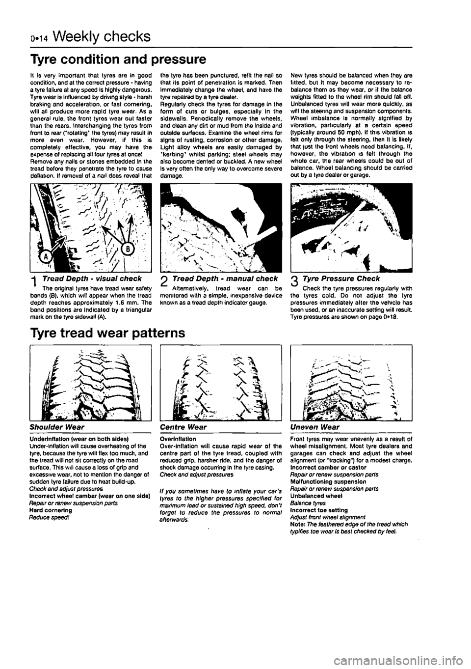
-j Tread Depth • visual check The original tyres have tread wear safety bands {8}, which wiU appear when the tread depth reaches approximately 1.6 mm. The band positions are indicated by a triangular mark on the tyre sidewail (A).
Tyre tread wear patterns
2 Tread Depth * manual check Alternatively, tread wear can be monitored with a simple, inexpensive device known as a tread depth indicator gauge.
2 Tyre Pressure Check Check the tyre pressures regularly with the tyres cold. Do not adjust the tyre pressures immediately alter the vehicle has been used, or an inaccurate setting will result Tyre pressures are shown on page 0*18.
Shoulder Wear Centre Wear Uneven Wear
Underinflatlon {wear an both sides) Under-lnflatton will cause overheating of the tyre, because the tyre will flex too much, and the tread will not sit correctly on the road surface. This will cause a loss of grip and excessive wear, not to mention the danger of sudden tyre failure due to heat build-up. Check and adjust pressures Incorrect wheel camber (wear on one side] Repair or renew suspension parts Hard cornering Reduce speed!
Overinflation Over-inflation will cause rapid wear of the centre part of the tyro tread, coupled with reduced grip, harsher ride, and the danger of shock damage occurring in the tyre casing. Check and adjust pressures
It you sometimes have (o inflate your car's tyres to the higher pressures specified tor maximum load or sustained high speed, don't forget to reduce the pressures to normal afterwards.
Front tyres may wear unevenly as a result of wheel misalignment. Most lyre dealers and garages can check and adjust the wheel alignment (or 'tracking") for a modest charge. Incorrect camber or castor Repair or renew suspension parts Malfunctioning suspension Repair or renew suspension parts Unbalanced wheel Balance tyres Incorrect toe setting Adjust front wheel alignment Note: The feathered edge of I he treed which typifies toe wear is best checked by feel.
Page 58 of 225
2A*10 SOHC (8-valve) petrol engine in-car repair procedures
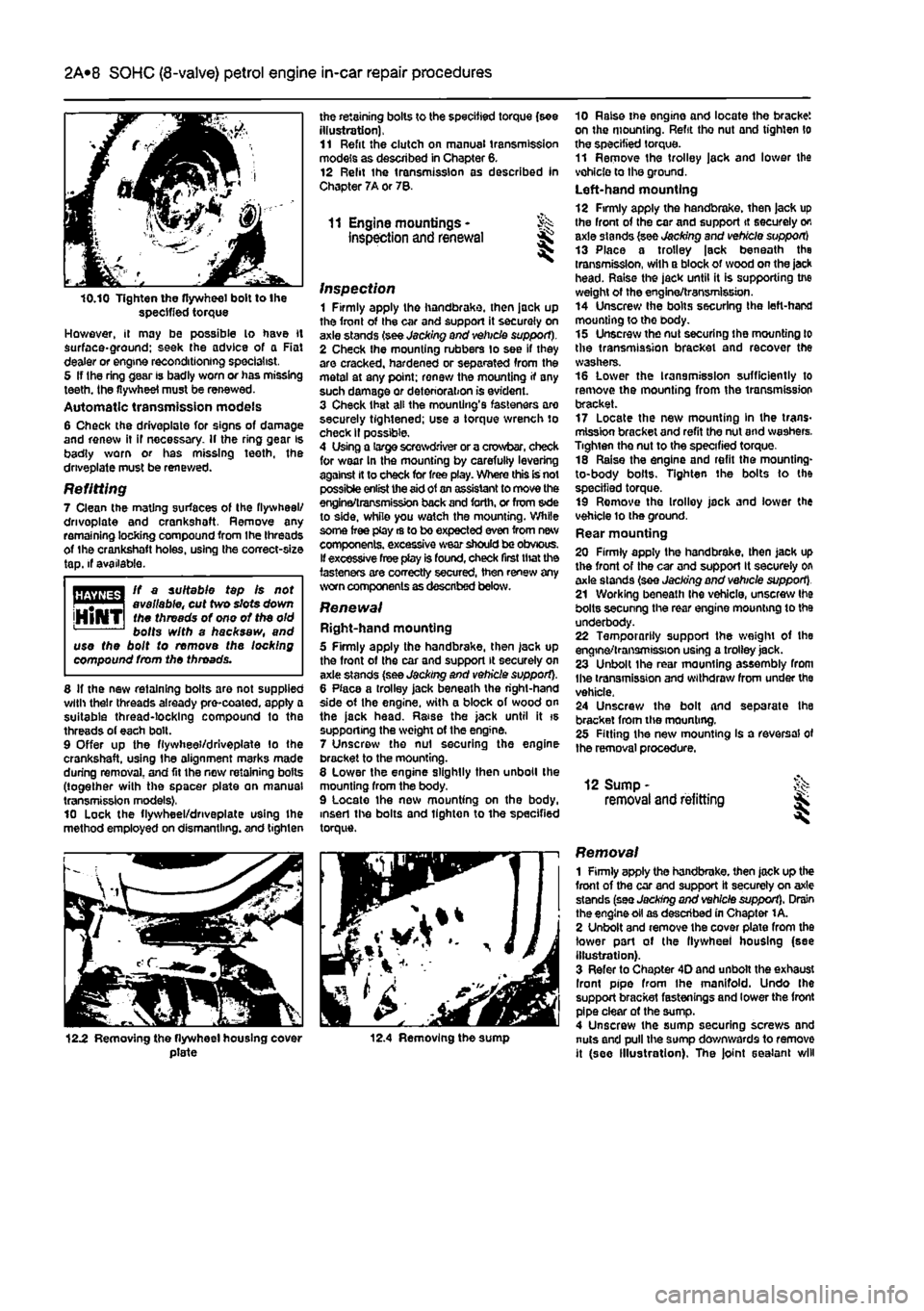
10.10 Tighten the flywheel bolt to the specified torque However, it may be possible lo have it surface*ground; seek (he advice of a Rat dealer or engine reconditioning specialist, 5 If Ihe ring gear is badly worn or has missing teeth, the flywheel must be renewed. Automatic transmission models 6 Check the driveplate for signs of damage and renew it if necessary. If the ring gear is badly worn or has missing teeth, the driveplate must be renewed.
Refitting 7 Clean the mating surfaces of the flywheel/ drivoplate and crankshoft. Remove any remaining locking compound from the threads of the crankshaft holes, using the correct-size tap. if available.
ft a suitable tap fs not . # | available, cut two slots down jHlNTI
toe
threads of ono of the old bolts with a hacksaw, and use the bolt to remove the locking compound from the throads.
8 If the new retaining bolts are not supplied with their threads already pre-coated, apply a suitable thread-locking compound to the threads of each bolt. 9 Offer up the fiywhee'/drlveplate lo the crankshaft, using the alignment marks made during removal, and fit the new retaining bolts (together with the spacer plate on manual transmission models), 10 Lock the flywheel/dnveplate using Ihe method employed on dismantling, and tighten
the retaining bolts to the specified torque (see illustration), 11 Refit the clutch on manual transmission models as described in Chapter 6. 12 Relit the transmission as described In Chapter 7A or 78.
11 Engine mountings • inspection and renewal
inspection 1 Firmly apply the handbrake, then jack up the front of the car and support it securely on axle stands (see Jacking and vehicle support). 2 Check Ihe mounting rubbers to see if they are cracked, hardened or separated from the metal at any point; renew the mounting if any such damage or deterioration is evident. 3 Check that all the mounting's fasteners are securely tightened; use a torque wrench to check II possible. 4 Using a large screwdriver or a crowbar, check for wear In the mounting by carefuliy levering against It to check for free play. Where this is not possible enlist the
aid
of
an
assistant to move the engina/transmission back
and
forth, or from s»de to side, while you watch the mounting. While some free play rs to bo expected even from new components, excessive wear
should
be obvious. If excessive free play is found, check first that the fasteners are correctly secured, then renew any worn components as described below.
Renewal Right-hand mounting 5 Firmly apply the handbrake, then jack up the front of the car and support it securely on axle stands (see Jacking and vehicle support). 8 Place a trolley jack beneath the right-hand side of Ihe engine, with a block of wood on the jack head. Raise the jack until it is supporting the weight of the engine. 7 Unscrew the nut securing the engine bracket to the mounting. 8 Lower the engine slightly then unboll the mounting from the body. 9 Locate the new mounting on the body, insert the bolts and tighten to the specified torque.
10 Raise tne engine and locate the bracket on the mounting. Refit tho nut and tighten lo the specified torque. 11 Remove the trolley jack and lower the vehicle to the ground. Left-hand mounting 12 Firmly apply the handbrake, then jack up the front of the car and support it securely on axle stands (see Jacking and vehicle support) 13 Place a trolley |sck beneath the transmission, with a block of wood on the jack head. Raise the jack until it is supporting tne weight of the engine/transmission. 14 Unscrew Ihe bolts securing the left-hand mounting to tho body. 15 Unscrew the nut securing ihe mounting to the transmission bracket and recover the washers. 16 Lower the transmission sufficiently to remove the mounting from the transmission bracket. 17 Locate the new mounting In the trans-mission bracket and refit the nut and washers. Tighten the nut to the specified torque. 18 Raise the engine and refit the mounting-to-body bolts. Tighten the bolts to the specified torque. 19 Remove the Irolloy jack and lower the vehicle lo the ground. Rear mounting 20 Firmly apply the handbrake, then Jack up the front of the car and support It securely on axle stands (see Jacking and vehicle support). 21 Working beneath Ihe vehicle, unscrew Ihe bolts secunng the rear engine mounting to the underbody. 22 Temporarily support the weight of the engine/transmission using a trolley jack. 23 Unbolt the rear mounting assembly from Ihe transmission and withdraw from under the vehicle. 24 Unscrew the bolt and separate Ihe bracket from tlve mounting. 28 Fitting the new mounting Is a reversal of the removal procedure.
12 Sump -removal and refitting
12.2 Removing the flywheel housing cover plate 12.4 Removing the sump
Removal 1 Firmly apply the handbrake, then jack up the front of the car and support it securely on axle stands (see Jacking and vehicle support). Drain the engine oil as described in Chapter 1 A. 2 Unbolt and remove the cover plate from the lower pari of the llywheel housing (see illustration). 3 Refer to Chapter 4D and unbolt the exhaust Iront pipe from Ihe manifold. Undo Ihe support bracket fastenings and lower the front pipe clear of the sump. 4 Unscrew the sump securing screws and nuts and pull the sump downwards to remove it (see Illustration). The joint sealant will
Page 172 of 225
6*172
Chapter 8
Driveshafts
Contents
Oriveshaft gaiter check See Chapter 1A or 1B General information 1 Oriveshaft overhaul and rubber gaiter renewal 3 intermediate driveshaft - removal and refitting 4 Driveshafts - removal and refitting 2
Degrees of difficulty
Easy,
suitable for ^ novtoewithittle experience ^
Fatly
easy,
suitable for beginner with
some experience
^
Fairty
difficult, suitable
tor
competent OtYmechanlc
Difficult,
suitable for experienced DIY mechanic ^
Veiydfficult, ^
suitable
for
expert DIY
or professional ^
Specifications
General Type
Lubrication lubricant type
Torque wrench settings Driveshaft nut* All models except turbo diesel (M22 plain) Turbo diesel (M24 with staking and captive washer) Roadwheel bolts Suspension strut-to-hub carrier bolts Track-rod balljolnt-to-hub carrier 'Use a new nut.
Unequal-length, solid steel shafts, splined to Inner and outer constant velocity joints. Intermediate shaft with support bearing on turbo diesel models with equal length driveshafts.
Fiat specification grease, supplied with gaiter repair kit
Nm Ibfft
240 177 280 207 85 63 70 52 40 30
1 General information
Power is transmitted from the differential to
Ihe
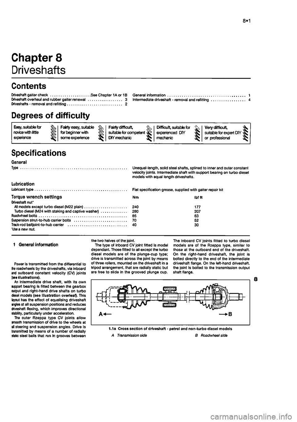
roadwheels by the driveshafts. via inboard and outboard constant velocity (CV) joints (we illustrations). An intermediate drive shaft, with its own support bearing is fitted between the gearbox output and right-hand drive shafts on turbo desei models (see Illustration overleaf). This layout has the effect of equalising driveshaft angles at sll suspension positions and reduces tfveshaft flexing, which improves directional stability, particularly under acceleration. The outer Rzeppa type CV joints allow smooth transmission of drive to the wheels at all steering and suspension angles. Drive Is transmitted by means of a number of radially static steel balls that run In grooves between
the two halves of the joint. The type of inboard CV joint fitted is model dependant. Those fitted to all except the turbo diesel models are of the plunge-cup type; drive is transmitted across the joint by means of three rollers, mounted on the driveshaft in a tripod arrangement, that are radially static but are free to slide in the grooved plunge cup.
The inboard CV joints fitted to turbo diesel models are of the Rzeppa type, similar to those at the outboard end of the driveshaft. On the right-hand driveshafl, the joint is bolted directly to the end of the intermediate driveshaft flange. On the left-hand driveshaft, the joint is bolted to the transmission output shaft flange.
1.1a Cross section of driveshaft - petrol and non-turbo diesel models A Transmission side B Roadwheef side
Page 189 of 225
10*1
Chapter 10
Suspension and steering
Contents
Front hub bearings - renewal 2 Front suspension anti-roll bar • removal and refitting 6 Front suspension lower arm - removal and refitting 4 Front suspension lower arm balljolnt - renewal 5 From suspension strut - removal, overhaul and refitting 3 General information 1 Ignition switch/steering column lock - removal and refitting 10 Manual steering gear assembly - removal, overhaul and refitting ... 12 Power steering fluid level check See Weekly checks Power steering gear assembly - removal and refitting 13 Power steering hydraulic system - bleeding 15
Degrees of difficulty
Power steering pump • removal and refitting 16 Rear hub bearings - renewal 7 Rear suspension components- removal, overhaul and refitting 8 Steering and suspension check See Chapter 1A or 1B Steering column - removal, overhaul and refitting 11 Steering gear rubber gaiters - renewal 14 Steering wheel - removal and refitting 9 Track-rod end - removal and refitting 17 Wheel alignment and steering angles • general information 18 Wheel and tyre maintenance and tyre pressure checks See Weekly checks
Easy, suitable for nowoe with little
Jg experience ^
Fakty easy,
suitable for beginner
with
J£>
some experience
^
FaMy difficult,
% suitable for competent ^
DIY mechanic
^
Difficult,
suitable for & experienced DIY « mechsmc ^
Very difficult,
^ suitable for expert
DIY
fij or professional ^
Specifications
Front suspension Type
Rear suspension Type
Steering Type Turns lock-to-lock: Manual Power assisted Toe setting (front)
Roadwheeis and tyres See Weekly checks
Torque wrench settings Front suspension Anti-roll bar bush bracket bolts Driveshaft nut:' All models except turbo diesel (M22 plain) Turbo diesel (M24 with staking and captive washer) Lower arm balljoint to hub carrier Lower arm front bush securing bolt Lower arm rear bush securing bolt Suspension strut damper nut Suspension strut to hub carrier Suspension strut to inner wing
Independent, incorporating transverse lower wishbones and coil spring-over-teiescopic damper strut units. Anti-roll bar fitted to all models.
Independent, incorporating trailing arms with telescopic dampers and coil springs.
Rack-and-pinlon, manual or power assisted, depending on model
4.4 approx. 2.9 approx. 0° (parallel) ± 1a
Nm ibfft
30 22
240 177 280 207 30 22 95 70 70 52 60 44 70 52 50 37
Page 200 of 225
10*12 Suspension and steering
16.4b ... and through-bolt...
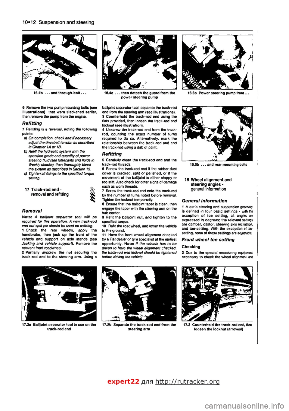
6 Remove the two pump mounting bolts (see Illustrations) that were slackened earlier, then remove the pump from the engine.
Refitting 7 Refilling is a reversal, noting the following points: a) On completion, check and j? necessary adjust the dm'ebelt tension ay described In Chapter JA or IB. b) Refill the hydraulic system with the specified grade and quantity of power steering fluid (sw lubricants and fluids in Weekly checks), then thoroughly bleed the system as described In Section 15. c) Tighten all fixings to the specified torque setting,
17 Track-rod end -removal and refitting ^ S
Removal Note: A ball joint separator tool will do required for this operation. A new track-rod end nut split pin should be used on refitting. 1 Chock the rear wheels, apply the handbrake,
I
hen jack up Ihe front of the vehicle and support on axle stands (see Jacking and vehicle support). Remove the relevant front roadwheel. 2 Partially unscrew the nut securing the (rack-rod end to the steering arm. Using a
17.2a Balljoint separator tool In use on the track-rod end
16.4c ... then detach the guard from the power steering pump
ballpoint separator tool, separate Ihe track-rod end from tho steering arm (see Illustrations). 3 Counterhold the track-rod end using the flats provided, then loosen ihe irack-rod end locknut (see illustration). 4 Unscrew the track-rod end from the track-rod, counting the exact number of turns required to do so. Alternatively, mark the relationship between the track-rod end and the trock-rod using a dab of p3lnL
Refitting 5 Carefully clean the track-rod end and the track-rod threads. 6 Renew the track-rod end if the rubber dust cover Is cracked, split or perished, or If the movement of the balijoint is either sloppy or too stiff. Also check lor other signs of damage such as worn threads. 7 Screw the track-rod end onto ihe track-rod by ihe number ol turns noted before removal. Tighten the locknut temporarily. 8 Ensure that Ihe balljoint taper is clean, then engage the taper wilh the steering arm on the hub carrier. 9 Refit the balljoint nut, and tighten to the specified torque. 10 Refit the roadwheel, and lower the vehicle to the ground. 11 Have tho front wheel alignment checked by a Rat dealer or tyre specialist at the earliest opportunity. Note: // the vehicle has to be driven to have the wheel alignment checked, the track-rod end locknut should be tightened before drMng the vehicle.
17.2b Separato tho track-rod end from the steering arm
18.6b ... and rear mounting bolts
18 Wheel alignment and steering angles -general information
General information 1 A car's steering and suspension geomeiry Is defined in four basic settings • with this exception of toe sotting, all angles arc expressed in degrees: the relevant setting! are camber, castor, steering axis inclination, and toe-setting. With ihe exception of toe-sett ing, none of these settings are acfjustabitf.
Front wheel toe setting
Chocking 2 Due to the special measuring equlpr
expert22 fl/m http://rutracker.org
Page 201 of 225
Suspension and steering 10*13
the skill required to use It properly, the checking and adjustment of these settings Is best left to a Fiat dealer or similar expert. Most tyre-fitting shops now possess sophisticated checking equipment. 3 For accurate checking, the vehicle must be at the kerb weight specified in Dimensions and weights. 4 Before starting work, check first that the tyre sizes and types are as specified (see Tyre pressures in Weekly checks), then check tyre pressures and tread wear. Also check roadwheel run-out, the condition of the hub bearings, the steering wheel free play and the condition of the front suspension components (Steering and suspension check in Chapter 1A or
1B).
Correct any faults found. 6 Park the vehicle on level ground, with the front roadwheeis in the straight-ahead position. Rock the rear and front ends to settle the suspension. Release the handbrake and roll the vehicle backwards approximately 1 metre, then forwards again, to relieve any stresses in the steering and suspension components. 6 Two methods are available to the home mechanic for checking the front wheel toe setting. One method is to use a gauge to measure the distance between the front and rear inside edges of the roadwheeis. The other method is to use a scuff plate, in which each front wheel is rolled across a movable plate which records any deviation, or scuff, of the tyre from the straight-ahead position as It moves across the plate. Such gauges are available in relatively-inexpensive form from accessory outlets. It Is up to the owner to decide whether the expense is justified, In view of the small amount of use such equipment would normally receive. 7 Prepare the vehicle 8S described in paragraphs 3 to 5 above.
8 If the measurement procedure is being used, carefully measure the distance between the front edges of the roadwheel rims and the rear edges of the rims. Subtract the front measurement from the rear measurement, and check that the result is within the specified range. If not, adjust the toe setting as described in paragraph 10. 9 If scuff plates are to be used, roll the vehicle backwards, check that the roadwheeis are in the straight-ahead position, then roll it across the scuff plates so that each front roadwheel passes squarely over the centre of its respective plate. Note the angle recorded by the scuff plates. To ensure accuracy, repeat the check three times, and take the average of the three readings, if the roadwheeis are running parallel, there will of course be no angle recorded; If a deviation value Is shown on the scuff plates, compare the reading obtained for each wheel with that supplied by the scuff plate manufacturers. If the value recorded is outside Ihe specified tolerance, the toe setting is incorrect, and must be adjusted as follows. Adjustment 10 Apply the handbrake, then jack up the front of the vehicle and support it securely on axle stands (see Jacking and vehicle support). Turn the steering wheel onto full-left lock, and record the number of exposed threads on the right-hand track-rod. Now turn the steering onto full-right lock, and record the number of threads on the left-hand side. If there are the same number of threads visible on both sides, then subsequent adjustment should be made equally on both sides. If there are more threads visible on one side than the other, it will be necessary to compensate for this during adjustment Note: It is important to ensure that, after adjustment, the same number of threads are visible on the end of each track-rod.
11 First clean the track-rod threads; If they are corroded, apply penetrating fluid before starting adjustment. Release the steering gear rubber gaiter outboard clips, then peel back the gaiters and apply a smear of grease, so that both gaiters are free and will not be twisted or strained as their respective track-rods are rotated. 12 Use a straight-edge and a scriber or similar to mark the relationship of each track-rod to the track-rod end. Working on each track-rod end in tum, unscrew its locking nut. 13 Alter the length of the track-rods, bearing In mind the note in paragraph 10, by screwing them into or out of the track-rod ends. Rotate the track-rod using an open-ended spanner fitted to the flats provided. If necessary, counterhold the track-rod end using a second spanner. Shortening the track-rods (screwing them Into their track-rod ends) will reduce toe-in and increase toe-out. 14 When the setting Is correct, hold the track-rods and securely tighten the locking nuts. Check that the balljoints are seated correctly In their sockets, and count the exposed threads on the ends of the track-rods. If the number of threads exposed is not the same on both sides, then the adjustment has not been made equally, and problems will be encountered with tyre scrubbing in turns; also, the steering wheel spokes will no longer be horizontal when the wheels are in the straight-ahead position. 15 When the track-rod lengths are the same, lower the vehicle to the ground and re-check the toe setting; readjust if necessary. When the setting is correct, tighten the locking nuts. Ensure that the steering gear rubber gaiters are seated correctly and are not twisted or strained, then secure them In position with new retaining clips.
10