bolt pattern FIAT PUNTO 1995 176 / 1.G Workshop Manual
[x] Cancel search | Manufacturer: FIAT, Model Year: 1995, Model line: PUNTO, Model: FIAT PUNTO 1995 176 / 1.GPages: 225, PDF Size: 18.54 MB
Page 63 of 225

2B*3 DOHC (16-valve) petrol engine in-car repair procedures
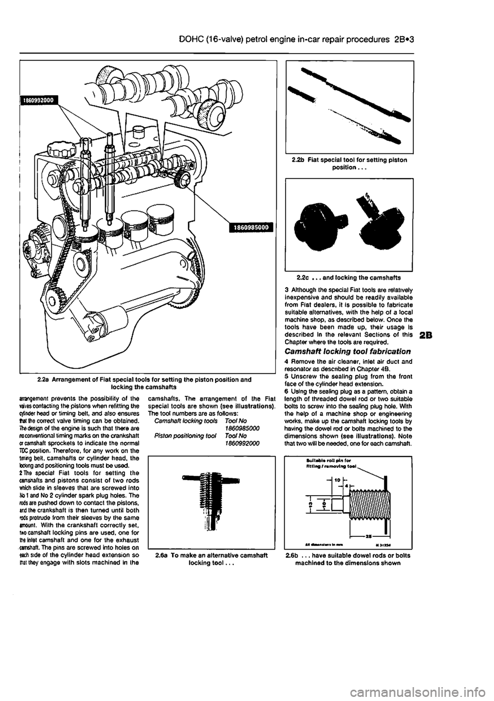
2.2s Arrangement of Fiat special tools for setting the piston position and locking the camshafts
arrangement prevents the possibility of the vaivescontacting the pistons when refitting the cinder head or timing belt, and also ensures tet the correct valve timing can be obtained.
The design
of the engine is such that there are n> conventional timing marks on the crankshaft
er
camshaft sprockets to indicate the normal 70C position. Therefore, for any work on the lining belt, camshafls or cylinder head, the b&ng
and
positioning tools must be used.
2 The
special Fiat tools for setting the camshafts and pistons consist of two rods ttikh slide in sleeves that are screwed into
So
t and No 2 cylinder spark plug holes. The
rods are
pushed down to contact the pistons, ird the crankshaft is then turned until both tods protrude from their sleeves by the same enount. With the crankshaft correctly set,
ti»o
camshaft locking pins are used, one for tM inlet camshaft and one for the exhaust earretaft. The pins are screwed into holes on *ach »de of the cylinder head extension so M they engage with slots machined In (he
2.2b Fiat special tool for setting piston position...
camshafts. The arrangement of the Rat special tools are shown (see illustrations). The tool numbers are as follows: Camshaft locking toots Toot No 1860985000 Piston positioning tool Toot No 1860992000
2.2c ... and locking the camshafts
3 Although the special Fiat tools are relatively inexpensive and should be readily available from Flat dealers, it is possible to fabricate suitable alternatives, with the help of a local machine shop, as described below. Once the tools have been made up, their usage Is described In the relevant Sections of this Chapter where the tools are required. Camshaft locking tool fabrication 4 Remove the air cleaner, inlet air duct and resonator as descnbed in Chapter 4B. 5 Unscrew the sealing plug from the front face of the cylinder head extension. 6 Using the sealing plug as a pattern, obtain a length of threaded dowel rod or two suitable bolts to screw into the sealing plug hole. With the help of a machine shop or engineering works, make up the camshaft locking toots by having the dowel rod or bolts machined to the dimensions shown (see illustrations). Note that two will be needed, one for each camshaft.
Suitabt* roll pin (or titling /
ramoviitg
tool
-J 10 h -4 h
AT —
T
—
2,6a To make an alternative camshaft locking tool... 2.6b ... have suitable dowel rods or bolts machined to the dimensions shown
Page 114 of 225

3*2 Cooling, heating and ventilation systems
1 General information and precautions
Genera/ Information The engine cooling/cabin heating system is ol pressurised type, comprising a coolant pump driven by the camshaft timing belt (petrol engine models) or auxiliary drlvebelt (diesel engine models), a crossllow radiator, a coolant expansion tank, an electric cooling fan, a thermostat, heater matrix, and all associated hoses and switches. The system functions as follows: Ihe coolant pump circulates cold water around the cylinder block and head passages, and through the Inlet manifold, heater matrix and throttle body to the thermostat housing. When the engine Is cold, the thermostat remains closed and prevents coolant from circulating through the radiator. When the coolant reaches a predetermined temperature, the thermostat opens, and the coolant passes through the top hose to the radiator. As the coolant circulates through the radiator, it is cooled by the in-rush of air when the car is in forward motion. The airllow is supplemented by the action of the electric cooling fan. when necessary, As the temperature of the coolant in the radiator drops, it flows to the bottom of the radiator by convection, and passes out through the bottom hose to the coolant pump - the cycle is then repeatod, When the engine is at normal operating temperature, the coolant expands, and some of It is displaced into the expansion tank. Coolant collects In the tank, and ts returned to Ihe radiator when the system cools. On petrol engine models, the expansion tank is integrated into the side of the radiator. On diesel engine models, and certain petrol engine models with air conditioning, the tank is a separate unit, mounted on the right hand side of the engine compartment. On turbo diesel engine models, the coolant is also passed through a supplementary engine oil cooler, to assist In controlling the engine lubricant temperature. Tho electric cooling fan mounted in front of the radiator is controlled by a thermostatic switch. At a predetermined coolant temperature, the swilch/sensor actuates the tan lo provide additional airflow through the radiator, The switch cuts the electrical supply to the Ion when the coolant temperature has dropped below a preset threshold (see Specifications).
Precautions
A
Warning: Do not attempt to remove the expansion tank pressure cap, or to disturb any part of the cooling system, whlio the engine is hot, as then is a high risk of scalding, tf the expansion tank pressure cap must be removed before the
engine and radiator have fulty cooled (even though this is not recommended?, the pressure in the cooling system must first be relieved. Cover the cap with a thick layer of cloth, to avoid scalding, and slowly unscrew the pressuro cap until a hissing sound Is heard. When the hissing stops, indicating that the pressure has reduced, slowly unscrew the pressure cap until it can be removed; If more hissing sounds are heard, wait until they have stopped before unscrewing the cap completely. At all times, keep your face well away from the pressure cap opening, and protect your hands.
A
Warning: Do not allow antifreeze to come into contact with your skin, or with the painted surfaces of the vehicle. Rinse off spills immediately, with plenty of water. Never leave antifreeze lying around in an open container, or In a puddle In the driveway or on the garage floor. Children and pets are attracted by its sweet smell, but antifreeze can be fatal tf ingested.
A
Warning: If the engine is hot, the electric cooling fan may start rotating even if the engine and ignition are switched off. Be careful to keep your hands, hair, and any loose clothing well clear when working In the engine compartment.
2 Cooling system hoses - f&> disconnection and renewal ^
1 The number, routing and pattern of hoses will vary according to model, but the same basic procedure applies. Before commencing work, make sure that the new hoses are to hand, along wilh new hose clips if needed, it is good practice to renew the hose clips at the same time as the hoses. 2 Drain the cooling system, as described in Chapter 1A or 18, saving the coolant if it is fit for re-use. Apply a little penetrating oil onto the hose clips if they are corroded. 3 Release the hose clips from the hose concerned. Three types of clip are used; worm-drive. spring and 'sardine-can'. The worm-drive clip is released by turning its screw anti-clockwise. The spring clip Is released by squeezing Its tags together with pliers, at the same time working the cbp away from the hose stub. The sardine-can clips are not re-usable, and are best cut off with snips or side cutters. 4 Unclip any wires, cables or other hoses which may be attached to the hose being removed. Make notes for reference when reassembling If necessary. 5 Release the hose from its stubs with a twisting motion. Be careful not to damage the stubs on deltcate components such as the radiator, or thermostat housings. If the hose Is stuck fast, the best course is often to cut it off using a sharp knife, but again be careful not to damage the stubs.
6 Before fitting the new hose, smear the stubs with washing-up liquid or a suitable rubber lubricant to aid fitting. Do not use oil or grease, which may attack the rubber. 7 Fit the hose clips over the ends of the hose, then fit the hose over its stubs. Work the hose Into position. When satisfied, locate and tighten the hose dips. 6 Refill the cooling system as described In Chapter 1A or 1B. Run the engine, and chock that there are no leaks. 9 Recheck the tightness of Ihe hose clips on any new hoses after a few hundred miles. 10 Top-up the coolant level if necessary.
3 Radiator -
removal,
inspection and refitting
Removal Note: If leakage is the reason for removing
the
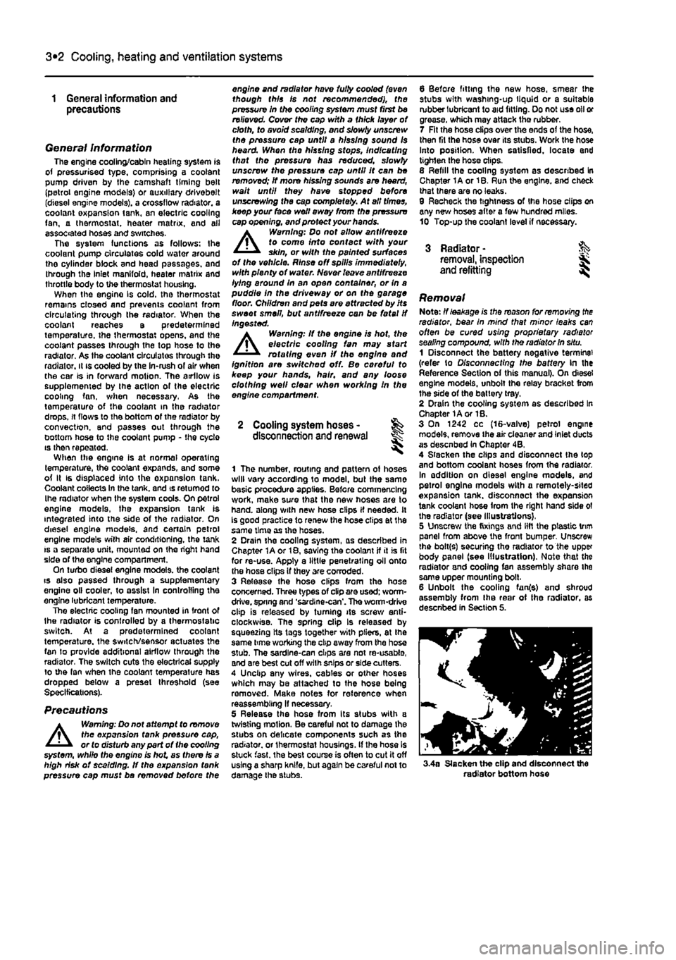
radiator, bear In mind that minor leaks can often be cured using proprietary radiator sealing compound, with the radiator in situ. 1 Disconnect the battery negative terminal (refer to Disconnecting the battery In the Reference Section of this manual). On diesel engine models, unbolt the relay bracket from the side of the battery tray. 2 Drain the cooling system as described In Chapter 1A or 1B. 3 On 1242 cc (16-valve) petrol engine models, remove the air cleaner and Inlet ducts as desenbed In Chapter 4B, 4 Slacken the clips and disconnect Ihe (op and bottom coolant hoses from the radiator. In addition on diesel engine models, and petrol engine models with a remotely-sited expansion tank, disconnect the expansion tank coolant hose from the right hand side ol the radiator (see Illustrations), 5 Unscrew the fixings and lift the plastic trim panel from above the front bumper Unscrew the bolt(s) securing tho radiator to the upper body panel (see Illustration). Note that the radiator and cooling fan assembly share the same upper mounting bolt. 6 Unbolt the cooling fan(e) and shroud assembly from Ihe rear ot the radiator, as described in Section 5.
3.4a Slacken the clip and disconnect the radiator bottom hose