central locking FIAT PUNTO 1995 176 / 1.G Workshop Manual
[x] Cancel search | Manufacturer: FIAT, Model Year: 1995, Model line: PUNTO, Model: FIAT PUNTO 1995 176 / 1.GPages: 225, PDF Size: 18.54 MB
Page 124 of 225

4A*2 Fuel system - single-point petrol Injection models
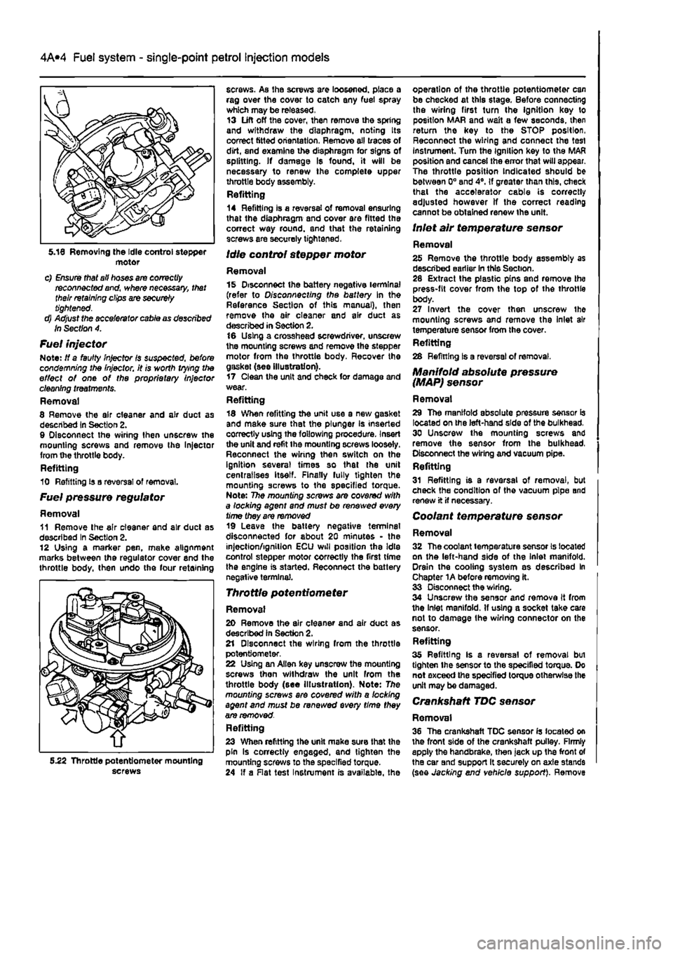
motor c) Ensure that all hoses are correctly reconnected and, where necessary, that their retaining clips are securely tightened. d) Adjust the accelerator cable as described In Section 4.
Fuel injector Note: If a faulty Injector Is suspected, before condemning the Injector, it is worth vying the effect of one of the proprietary Injector cleaning treatments. Removal 8 Remove the air cleaner and air duct as described In Section 2. 9 Disconnect the wiring then unscrew the mounting screws and remove Ihe Injector from the throttle body. Refitting 10 Refitting is a reversal of removal.
Fuel pressure regulator
Removal 11 Remove Ihe air cleaner and air duel as described In Section 2. 12 Using a marker pen. make alignment marks between the regulator cover end the throttle body, then undo the four retaining
screws. As the screws are loosened, place a rag over the cover to catch any fuel spray which may be released. 13 Lift off the cover, then remove the spring and withdraw the diaphragm, noting Its correct fitted orientation. Remove all traces of dirt, and examine the diaphragm for signs of splitting. If damage Is found, it will be necessary to renew the complete upper throttle body assembly. Refitting 14 Refitting is a reversal of removal ensuring that the diaphragm and cover are fitted the correct way round, and that the retaining screws are securely tightened,
Idle control stepper motor
Removal 15 Disconnect the battery negative terminal (refer to Disconnecting the battery In the Reference Section of this manual), then remove the air cleaner and air duct as described in Section 2. 16 Using a crosshead screwdriver, unscrew the mounting screws and remove the stepper motor from the throttle body. Recover the gaskei (see illustration). 17 Clean the unit and check for damage and wear. Refitting 18 When refitting the unit use a new gasket and make sure that the plunger is inserted correctly using the following procedure. Insert the unit and refit the mounting screws loosely. Reconnect the wiring then switch on the ignition several times so that the unit centralises itself. Finally fully tighten the mounting screws to the specified torque. Note: The mounting screws are covered with a locking agent and must be renewed every time they are removed 19 Leave the battery negative terminal disconnected for about 20 minutes - the injection/ignition ECU will position the Idle control stepper motor correctly the first time the engine is started. Reconnect the battery negative terminal.
Throttle potentiometer
Removal 20 Remove the air cleaner and air duct as described in Section 2. 21 Disconnect the wiring from the throttle potentiometer. 22 Using an Allen key unscrew the mounting screws then withdraw the unit from the throttle body (see Illustration). Note: The mounting screws ere covered with a locking agent and must be renewed every time they are removed. Refitting 23 When refitting the unit make sure that the pin Is correctly engaged, and tighten the mounting screws to the specified torque. 24 If a Rat test Instrument is available, the
operation of the throttle potentiometer can be checked at this stage. Before connecting the wiring first turn Ihe ignition key to position MAR and wait a few seconds, then return the key to the STOP position, Reconnect the wiring and connect the test instrument. Turn the Ignition key to the MAR position and cancel the error that will appear. The throttle position Indicated should be between 0° and 4°. If greater than this, check thai the accelerator cable is correctly adjusted however If the correct reading cannot be obtained renew the unit.
Inlet air temperature sensor
Removal 25 Remove the throtlle body assembly as described earlier In this Section. 28 Extract the plastic pins and remove the press-fit cover from the top of the throttle body. 27 Invert the cover then unscrew the mounting screws and remove the Inlet air temperature sensor from the cover. Refitting 28 Refining Is a reversal of removal.
Manifold absolute pressure (MAP) sensor
Removal 29 The manifold absolute pressure sensor is located on the left-hand side of the bulkhead. 30 Unscrew the mounting screws and remove the sensor from the bulkhead, Disconnect the wiring and vacuum pipe. Refitting 31 Refitting is a reversal of removal, but check the condition of the vacuum pipe and renew it if necessary.
Coolant temperature sensor
Removal 32 The coolant temperature sensor Is located on the left-hand side of the inlet manifold. Drain the cooling system as described In Chapter 1A before removing it. 33 Disconnect the wiring. 34 Unscrew the sensor and remove It from the Inlet manifold. If using a socket take care not to damage Ihe wiring connector on the sensor. Refitting 35 Refitting Is a reversal of removal bui tighten Ihe sensor to the specified torque. Do not exceed the specified torque otherwise the unit may be damaged.
Crankshaft TDC sensor
Removal 36 The crankshaft TDC sensor Is located on the front side of the crankshaft pulley. Firmly apply the handbrake, then jack up the front of the car Bnd support It securely on axle stands (see Jacking end vehicle support). Remove 5.22 Throttle potentiometer mounting screws
Page 210 of 225

Bodywork and fittings
11
*9
16.5b ... and lift the handle assembly from the door manual). Refer to Section 14 and remove the door inner trim panei and sealing sheet.
Door handle
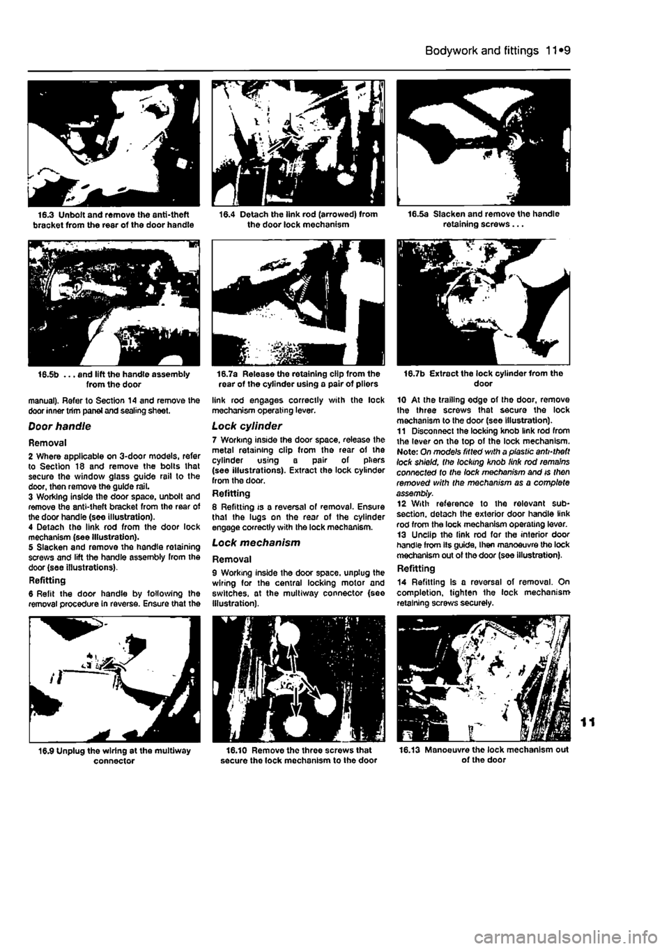
Removal 2 Where applicable on 3-door models, refer to Section 18 and remove the bolts lhat secure the window glass guide rail to the door, then remove the guide rail. 3 Working inside the door space, unbolt and remove the anti-theft bracket from the rear of the door handle (see illustration). 4 Detach the link rod from the door lock mechanism (see Illustration). 5 Slacken and remove the handle retaining screws and lift the handle assembly from the door (see illustrations). Refitting 6 Refit the door handle by following the removal procedure in reverse. Ensure that the
connector
16.7a Release the retaining clip from the rear of the cylinder using a pair of pliors
link rod engages correctly with the lock mechanism operating lever.
Lock cylinder 7 Working inside the door space, release the metal retaining clip from the rear of the cylinder using a pair of pliers (see illustrations). Extract the lock cylinder from the door. Refitting 8 Refitting is a reversal of removal. Ensure thai the lugs on the rear of the cylinder engage correctly with the lock mechanism. Lock mechanism
Removal 9 Working inside the door space, unplug the wiring for the central locking motor and switches, at the multiway connector {see Illustration).
16.10 Remove the three screws that secure the lock mechanism to the door
16.7b Extract the lock cylinder Irom tho door
10 At the trailing edge of the door, remove Ihe three screws that secure the lock mechanism to the door (see Illustration). 11 Disconnect the locking knob link rod from the lever on the top of the lock mechanism. Note: On mode's fitted with a plastic anti-theft lock shield, the locking knob link rod remains connected to the lock mechanism and is then removed with the mechanism as a complete assembly. 12 With reference to the relevant sub-section. detach the exterior door handle link rod from the lock mechanism operating lever. 13 Unclip the link rod for the interior door handle from lis guide, I hen manoeuvre the lock mechanism out of the door (see illustration). Refitting
14 Refitting is a reversal of removal. On completion, tighten the lock mechanism retaining screws securely.
16.13 Manoeuvre the lock mechanism out of the door