instrument panel FIAT PUNTO 1995 176 / 1.G Workshop Manual
[x] Cancel search | Manufacturer: FIAT, Model Year: 1995, Model line: PUNTO, Model: FIAT PUNTO 1995 176 / 1.GPages: 225, PDF Size: 18.54 MB
Page 26 of 225
Maintenance procedures - petrol models ia./
Every 5000 miles (7500 km) or 6 months
3 Engine oil and filter renewal Ja*
1 Frequent oil and filter changes are the most important preventative maintenance which can be undertaken by the DIY owner. As engine oil ages, it becomes diluted and contaminated, which leads to premature engine wear. 2 Before starting this procedure, gather all Ihe necessary tools and materials. Also make sure that you have plenty of clean rags and newspapers handy, to mop up any spills. Ideally, the engine oil should be warm, as It
will
drain better, and more built-up sludge will
be
removed with it. Tske care, however, not to touch the exhaust or any other hot parts of the engine when working under the vehicle. To avoid any possibility of scalding, and to protect yourself from possible skin irritants end other harmful contaminants in used engine oils, it Is advisable to wear gloves when carrying out this work. Access to the underside of the vehicle will be greatly Improved if it can be raised on a lift, driven onto ramps, or jacked up and supported on axle stands (see Jacking and vehicle support). Whichever method is chosen, make sure that
the
vehicle remains level, or if it is at an angle, that the drain plug Is at the lowest point. 3 Slacken the drain plug about half a turn using an Allen key. Position the draining container under the drain plug, then remove
the plug
completely (see Haynes Hint). 4 Allow some time for the old oil to dram, noting that it may be necessary to reposition
the
container as the oil flow slows to a trickle. 5 After all the oil has drained, wipe off the drain plug with a clean rag, then clean the area around the drain plug opening and refit
(MB
HiNT '
Keep the drain plug pressed Into the sump white unscrewing it by hand the last couple of turns. As the plug releases, move it away sharply so that the stream
of
oil Issuing from the sump runs into the container, net up your sleeve.
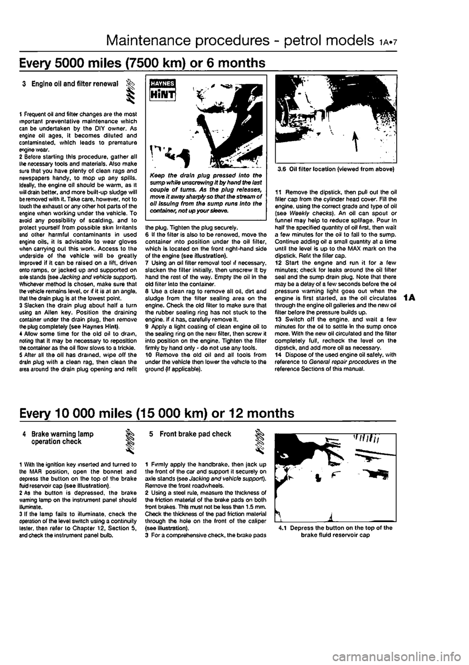
the plug. Tighten the plug securely. 6 It the filter is also to be renewed, move the container into position under tho oil filter, which is located on the front right-hand side of the engine (see illustration). 7 Using an oil filter removal tool if necessary, slacken the filter initially, then unscrew It by hand the rest of the way. Empty the oil in the old filter into the container. 8 Use a clean rag to remove all oil, dirt and sludge from the filter sealing area on the engine. Check the old filter to make sure that the rubber sealing ring has not stuck to the engine. If it has. carefully remove It. 9 Apply a light coating of clean engine oil to the sealing ring on the new filter, then screw it into position on the engine. Tighten the filter firmly by hand only • do not use any tools. 10 Remove the old oil and all tools from under the vehicle then lower the vehicle to the ground (if applicable).
3.6 Oil filter location (viewed from above)
11 Remove the dipstick, then pull out the oil filler cap from the cylinder head cover. Fill the engine, using the correct grade and type of oil (see Weekly checks). An oil can spout or funnel may help to reduce spillage. Pour In half the specified quantity of oil first, then wail a few minutes for the oil to fall to the sump. Continue adding oil a small quantity at a time until the level is up to the MAX mark on the dipstick. Refit the filler cap. 12 Start the engine and run it for a few minutes: check for leaks around the oil filter seal and the sump drain plug. Note that there may be a delay of a few seconds before the oil pressure warning light goes out when the engine is first started, as the oil circulates through the engine oil galleries and the new oil filter before (he pressure builds up. 13 Switch off the engine, and wait a few minutes for the oil to settle In the sump once more. With the new oil circulated and the filter completely full, recheck the level on the dipstick, and add more oil as necessary. 14 Dispose of the used engine oil safely, with reference to General repair procedures in the reference Sections of this manual.
Every 10 000 miles (15 000 km) or 12 months
4 Brake warning lamp ag operation check J§
1 With the ignition key inserted and turned to the MAR position, open the bonnet and depress the button on the top of the brake ftuid reservoir cap (see illustration). 2 As the button is depressed, the brake warning lamp on the instrument panel should Illuminate. 3 If the lamp fails to illuminate, check the operation of the level switch using a continuity tester, then refer to Chapter 12, Section 5, wd check the instrument panel bulb.
5 Front brake pad check
1 Firmly apply the handbrake, then jack up the front of the car and support it securely on axle stands (see Jacking and vehicle support). Remove the front roadwheels, 2 Using a steel rule, measure the thickness of the friction material of the brake pads on both front brakes- This must not be less than 1.5 mm. Check the thickness of the pad friction material through the hole on the front of the caliper (see illustration). 3 For a comprehensive check, the brake pads 4.1 Depress the button on the top of the brake fluid reservoir cap
Page 43 of 225
Maintenance procedures - diesel models ib.?
Every 10 000 miles (15 000 km) or 12 months
5 Brake warning lamp operation check 1
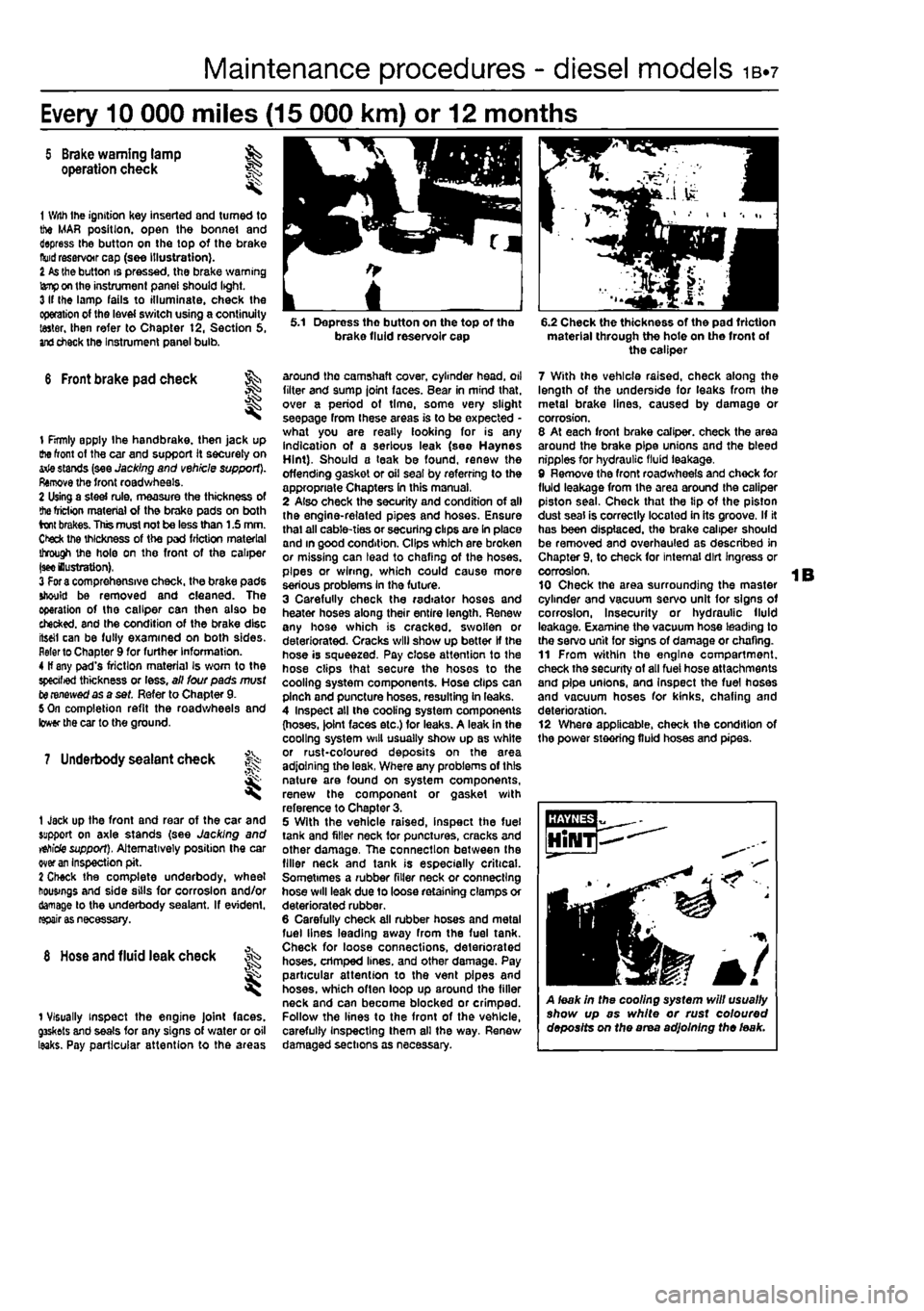
1 With Ihe ignition Key inserted and turned to the MAR position, open the bonnet and depress the button on the top of the brake
fluid
reservoir cap (see illustration). I
As
the button is pressed, the brake warning
lamp
on the instrument panel should light. 3 If Ihe lamp fails to illuminate, check the operation of the level switch using a continuity taster, then refer to Chapter t2, Section 5,
and
check the Instrument panel bulb.
6 Front brake pad check ^
I
1 firmly apply Ihe handbrake, then jack up the front of the car and support it securely on arie stands (see Jacking and vehicle support). Remove the front roadwheels. 2 Using a steel rule, measure the thickness of
the
friction material of the brake pads on both brakes. This must not be less than 1.5 mm. Ctefc the thickness of the pad friction material through the hole on the front of the caliper
|see
lustration), 3
For a
comprehensive check, the brake pads should be removed and cleaned. The operation of the caliper can then also bo checked, and the condition of the brake disc iteeil can be fully examined on both sides. Refer to Chapter 9 for further Information. 4 If any pad's friction material Is worn to the specified thickness or less, all lour pads must to renewed as a set. Refer to Chapter 9. 5 On completion refit the roadwheels and lower the car to the ground.
7 Underbody sealant check f^
1 Jack up the front and rear of the car and support on axle stands (see Jacking and
vehicle
support). Alternatively position the car over
an
Inspection pit. 2 Check the complete underbody, wheel housings and side sills for corrosion and/or damage to the underbody sealant. If evident,
rapairi
8
Hose
and fluid leak check
1 Visually inspect the engine Joint faces. g3skets and seals for any signs of water or oil leaks. Pay particular attention to the areas
5.1 Depress tho button on the top of the brake fluid reservoir cap
around the camshaft cover, cylinder head, oil filter and sump joint faces. Bear in mind that, over a period of time, some very slight seepage from these areas is to be expected -what you are really looking for is any indication of a serious leak (see Haynes Hint). Should a teak be found, renew the offending gasket or oil seal by referring to the appropriate Chapters In this manual, 2 Also check the security and condition of all the engine-related pipes and hoses. Ensure thai all cable-ties or securing clips are In place and in good condition. Clips which are broken or missing can lead to chafing of the hoses, pipes or wiring, which could cause more serious problems In the future. 3 Carefully check the radiator hoses and heater hoses along their entire length. Renew any hose which is cracked, swollen or deteriorated. Cracks will show up better If the hose is squeezed. Pay close attention to the hose clips that secure the hoses to the cooling system components. Hose clips can pinch and puncture hoses, resulting in leaks. 4 Inspect all the cooling system components (hoses. )olnt faces etc.) for leaks. A leak in the cooling system will usually show up as white or rust-coloured deposits on the area adjoining the leak, Where any problems of this nature are found on system components, renew the component or gasket with reference to Chapter 3. 5 With the vehicle raised, inspect the fuel tank and filler neck for punctures, cracks and other damage, The connection between the filler neck and tank is especially critical. Sometimes a rubber filler neck or connecting hose will leak due to loose retaining clamps or deteriorated rubber. 6 Carefully check all rubber hoses and metal fuel lines leading away from the fuel tank. Check for loose connections, deteriorated hoses, crimped lines, and other damage. Pay particular attention to the vent pipes and hoses, which often loop up around the filler neck and can become blocked or crimped. Follow the lines to the front of the vehicle, carefully Inspecting them all the way. Renew damaged sections as necessary.
6.2 Check the thickness of the pad friction material through the hote on the front of the caliper
7 With the vehicle raised, check along the length of the underside for leaks from the metal brake lines, caused by damage or corrosion. 8 At each front brake caliper, check the area around the brake pipe unions and the bleed nipples for hydraulic fluid leakage, 9 Remove the front roadwheels and chock for fluid leakage from the area around the caliper piston seal. Check that the tip of the piston dust seal is correctly located in its groove. If it has been displaced, the brake caliper should be removed and overhauled as described in Chapter 9, to check for internal dirt Ingress or corrosion. 10 Check the area surrounding the master cylinder and vacuum servo unit for signs of corrosion, Insecurity or hydraulic fluid leakage. Examine the vacuum hose leading to the servo unit for signs of damage or chafing. 11 From within the engine compartment, check the security of all fuel hose attachments and pipe unions, and Inspect the fuel hoses and vacuum hoses for kinks, chafing and deterioration. 12 Where applicable, check the condition of the power steering fluid hoses and pipes.
A leak in the cooling system will usually show up as white or rust coloured deposits on the area adjoining the leak.
Page 123 of 225
4A*2 Fuel system - single-point petrol Injection models
2.4a Disconnect the large breather hose... ziecessary when handling it cannot be mrstressed. Note that residual pressure
wttf
remain in the tuei lines long after the wh/cte was last used, When disconnecting any fuel line, first depressurise the fuel
system
(see Section 8).
2 Air cleaner and intet system • removal and refitting
1
Accelerator cable -removal, refitting and adjustment l
Removal 1 Remove the air cleaner element as described in Chapter 1A. 2 Disconnect the outer section from the hot
air
tube and the inlet air duct and remove it
from
the engine compartment. 3II necessary remove the inlet air duct. 4 Disconnect Ihe large and small breather
roses
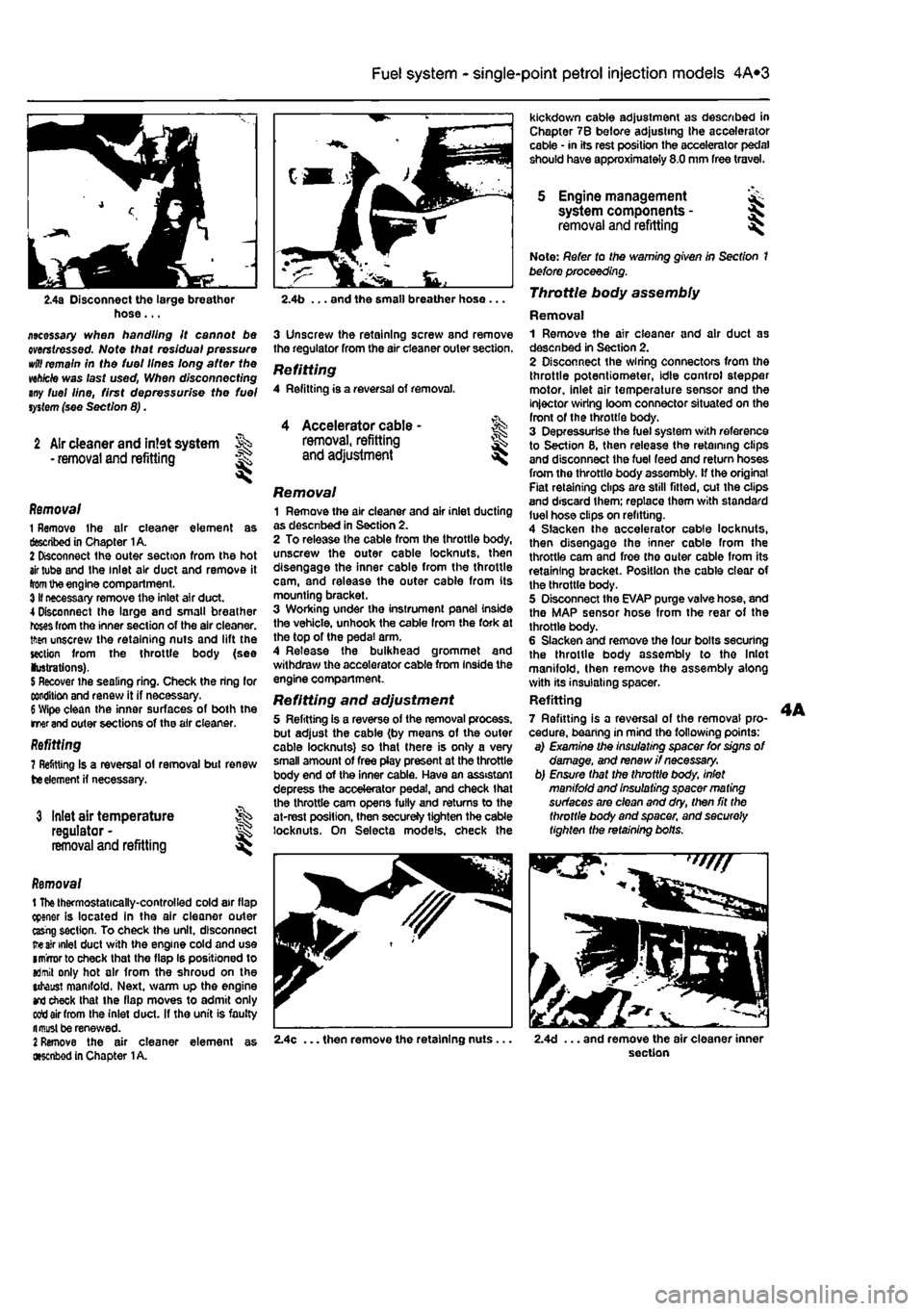
from the inner section of the air cleaner, tftsn unscrew the retaining nuts and lift the section from the throttle body (see lustrations).
5
Recover the sealing ring. Check the ring for condition and renew it if necessary.
6
Wipe clean the inner surfaces of both the merand outer sections of the air cleaner. Refitting 7 Refitting Is a reversal ol removal but renew
tie
element
H
necessary.
3 Inlet air temperature regulator -removal and refitting
Removal t
The
thermostatically-controlled cold air flap cpener is located in the air cleaner outer ttsrig section. To check the unit, disconnect
ire air
inlet duct with the engine cold and use imrrorto check that the flap Is positioned to aJmit only hot air from the shroud on the utaust manifold. Next, warm up the engine
and
check that the flap moves to admit only sett air from the inlet duct. If the unit is faulty fl must be renewed.
2
Remove the air cleaner element as •senbod in Chapter
1
A.
kickdown cable adjustment as described in Chapter 7B before adjusting the accelerator cable • in its rest position the accelerator pedal should have approximately 8.0 mm free travel.
5 Engine management system components -removal and refitting I
2.4b ... and the small breather hose ...
3 Unscrew the retaining screw and remove the regulator from the air cleaner outer section.
Refitting 4 Refitting is a reversal of removal.
Removal 1 Remove the air cleaner and air inlet ducting as desenbed in Section 2. 2 To release the cable from the throttle body, unscrew the outer cable locknuts, then disengage the inner cable from the throttle cam, and release the outer cable from its mounting bracket. 3 Working under the instrument panel inside the vehicle, unhook the cable from the fork at the top of the pedal arm. 4 Release the bulkhead grommet and withdraw the accelerator cable from Inside the engine compartment.
Refitting and adjustment 5 Refitting is a reverse of the removal process, but adjust the cable (by means of the outer cable locknuts) so that there is only a very small amount of free play present at the throttle body end of the inner cable. Have an assistant depress the accelerator pedal, and check that the throttle cam opens fully and returns to the at-rest position, then secureJy tighten the cable locknuts. On Selecta models, check the
Note: Refer to the warning given in Section 1 before proceeding. Throttle body assembly
Removal 1 Remove the air cleaner and air duct as desenbed in Section 2. 2 Disconnect the wiring connectors from the throttle potentiometer, idle control stepper motor, inlet air temperature sensor and the injector wiring loom connector situated on the front of the throttle body. 3 Depressurise the fuel system with reference to Section 8, then release the retaining clips and disconnect the fuel feed and return hoses from the throttle body assembly, if the original Fiat retaining clips are still fitted, cut the clips and discard them; replace them with standard luel hose clips on refitting. 4 Slacken the accelerator cable locknuts, then disengage the inner cable from the throttle cam and froe tho outer cable from its retaining bracket. Position the cable clear of the throttle body. 5 Disconnect the EVAP purge valve hose, and the MAP sensor hose from the rear of the throttle body. 6 Slacken and remove the four bolts securing the throttle body assembly to tho Inlet manifold, then remove the assembly along with its insulating spacer. Refitting 7 Refitting is a reversal of the removal pro-cedure, bearing in mind the following points: a) Examine the insulating spacer for signs of damage, and renew //necessary, b) Ensure that the throttle body, inlet manifold and insulating spacer ma ting surfaces are clean and dry, then fit the throttle body and spacer, and securely tighten the retaining bolts.
2.4c ... then remove the retaining nuts. 2.4d ... and remove the air cleaner inner section
Page 130 of 225
4A*2 Fuel system -
single-point
petrol Injection models
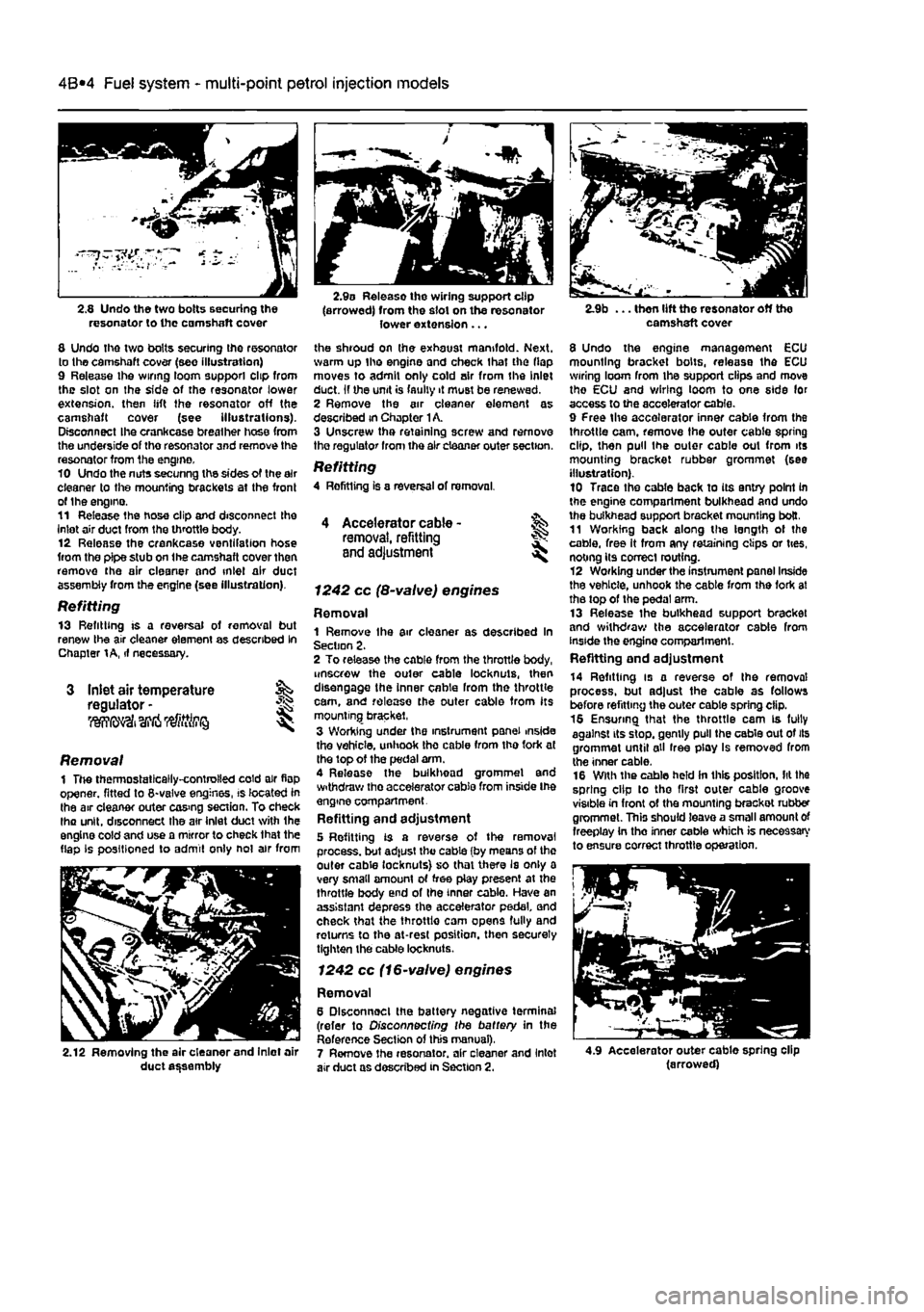
2.8 Undo tho two bolts securing the resonator to the camshaft cover
8 Undo the two bolts securing the resonator to the camshaft cover (see illustration) 9 Release ihe wiring loom support clip from the slot on the side of the resonator lower extension, then lift the resonator off the camshaft cover (see illustrations). Disconnect Ihe crankcase breather hose from the underside of tho resonator and remove the resonator from the engine. 10 Undo the nuts secunng the sides of the air cleaner to the mounting brackets at the front of the engino. 11 Release the hose clip and disconnect the inlet air duct from the throttle body. 12 Release the crankcase ventifation hose from the pipe stub on the camshaft cover then remove the air cleaner and inlet air duct assembly from the engine (see illustration).
Refitting 13 Refitting is a reversal of removal but renew the air cleaner element as described In Chapter
1 A,
if necessary.
Inlet air temperature regulator -liWfii' I
2.9o Release the wiring support clip (arrowed) from the slot on the resonator lower extension ...
the shroud on the exhaust manifold. Next, warm up tho engine and check that the flap moves to admit only cold air from the Inlet duct. If the unit is faulty it must be renewed. 2 Remove the air cleaner element as described in Chapter
1
A. 3 Unscrew tha retaining screw and remove tho regulator from the air cleaner outer section.
Refitting 4 Rofitting is a reversal of removal.
I
Removal 1 The thermostatically-controlled cold air flop opener, fitted to 8-valve engines, is located in the air cleaner outer cos>ng section. To check lha unit, disconnect the atr inlet duct with the engine cold and use a mirror to check that the flap Is positioned to admit only not air from
2.12 Removing the air cleaner and Inlet air duct assembly
4 Accelerator cable -removal, refitting and adjustment
1242 cc (8-valve) engines
Removal 1 Remove Ihe air cleaner as described In Section 2. 2 To release the cable from the throttle body, unscrew the outer cable locknuls, then disengage the inner cable from the throttle cam, and release the outer cable from its mounting bracket, 3 Wording under the instrument panel inside the vehicle, unhook the cable from tho fork at the top of the pedal arm. 4 Release the bulkhead grommel and withdraw tho accelerator cable from inside Ihe engine compartment. Refitting and adjustment 5 Refitting is a reverse of the removal process, but ad|ust the cable (by means of the outer cable locknuts} so that there Is only a very small amount of free play present at the throttle body end of the inner cablo. Have an assistant depress the accelerator pedal and check that the throttlo cam opens fully and returns to the at-rest position, then securely tighten the cable locknuts.
1242 cc (16-valve) engines
Removal 6 Dlsconnoel the battery negative terminal (refer to Disconnecting the battery in the Reference Section of this manual), 7 Remove the resonator, air cleaner and Inlet air duct as described in Section 2.
camshaft cover
8 Undo the engine management ECU mounting bracket bolts, release the ECU wiring loom from Ihe support clips and move tho ECU and wiring loom to one side for access to the accelerator cable. 9 Free the accelerator inner cable from the throttle cam, remove the outer cable spring clip, then pull the outer cable out from its mounting bracket rubber grommet (see illustration). 10 Trace the cable back to its entry point in the engine compartment bulkhead and undo the bulkhead support bracket mounting bolt. 11 Working back along the length of the cable, free It from any retaining clips or ties, noting its correct routing. 12 Working under the instrument panel Inside the vehicle, unhook the cable from the fork at the top of the pedal arm. 13 Release the bulkhead support bracket and withdraw the accelerator cable from inside the engino compartment. Refitting end adjustment
14 Refitting is a reverse of the removal process, but adjust the cable as follows before refitting the outer cable spring clip. 16 Ensuring that the throttle cam is fully against its stop, gently pull the cable out of its grommet until all free play Is removed from the inner cable. 16 With the cable held in this position, lit the spring clip to tho first outer cable groove visible in front of the mounting brackot rubber grommet. This should leave a small amount of freeplay in tho inner cable which is necessary to ensure correct throttle operation.
4.9 Accelerator outer cable spring clip (arrowed)
Page 138 of 225
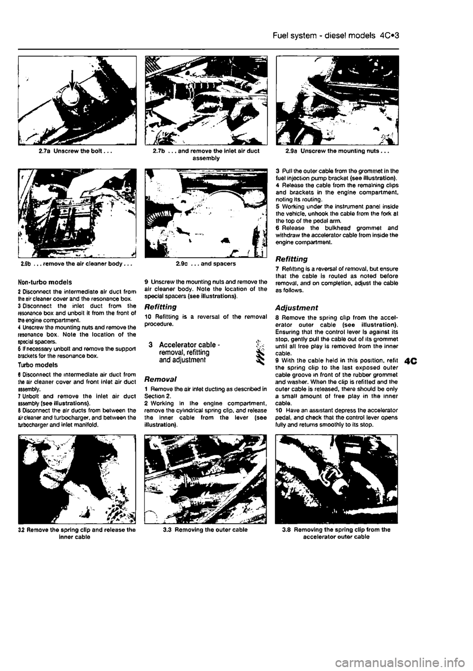
Fuel system - diesel models 4C*3
2.7a Unscrew the bolt... 2.7b ... and remove the Inlet air duct assembly
2.9b ... remove the air cleaner body...
Non-turbo models 2 Disconnect the intermediate air duct from
the
sir cleaner cover and the resonance box. 3 Disconnect the inlet duct from the resonance box and unbolt It from the front of
the
engine compartment. 4 Unscrew tho mounting nuts and remove the resonance box. Note the location of the special spacers. 6 If necessary unbolt and remove the support Brackets for the resonance box. Turbo models 6 Disconnect the intermediate air duct from the air cleaner cover and front Inlet air duct assembly. 7 Unbolt and remove the inlet oir duct tssembty (see illustrations). 6 Disconnect the air ducts from between the
air
cleaner and turbocharger. and between the turbocharger and Inlet manifold.
2.9c ... and spacers
9 Unscrew the mounting nuts and remove the air cleaner body. Note the location of the special spacers (see illustrations).
Refitting 10 Refitting is a reversal of the removal procedure.
3 Accelerator cable -removal, refitting and adjustment
Removal 1 Remove the air inlet ducting as described in Section 2. 2 Working In Ihe engine compartment, remove the cylindrical spring clip, and release the Inner cable from the lever (see illustration).
2.9a Unscrew the mounting nuts...
3 Pull the outer cable from the grommet in the fuel injection pump bracket (see illustration). 4 Release the cable from the remaining clips and brackets in the engine compartment, noting Its routing. 5 Working under the Instrument panel inside the vehicle, unhook the cable from the fork at the top of the pedal arm. 6 Release the bulkhead grommet and withdraw the accelerator cable from inside the engine compartment.
Refitting 7 Refitting Is a reversal of removal, but ensure that the cable is routed as noted before removal, and on completion, adjust the cable as follows.
Adjustment 8 Remove the spring clip from the accel-erator outer cable (see illustration). Ensuring that the control lever Is against its stop, gently pull the cable out of Its grommet until all Iree play is removed from the inner cable. 9 With the cable held In this position, refit the spring clip to the last exposed outer cable groove in front of the rubber grommet and washer. When the clip is refitted and the outer cable is released, there should be only a small amount of free play in the inner cable. 10 Have an assistant depress the accelerator pedal, and check that the control lever opens lulty and returns smoothly to its stop.
4C
32 Remove the spring clip and release the inner cable 3.3 Removing the outer cable 3.8 Removing the spring clip Irom the accelerator outer cable
Page 143 of 225
Fuel system - diesel models 4C*3
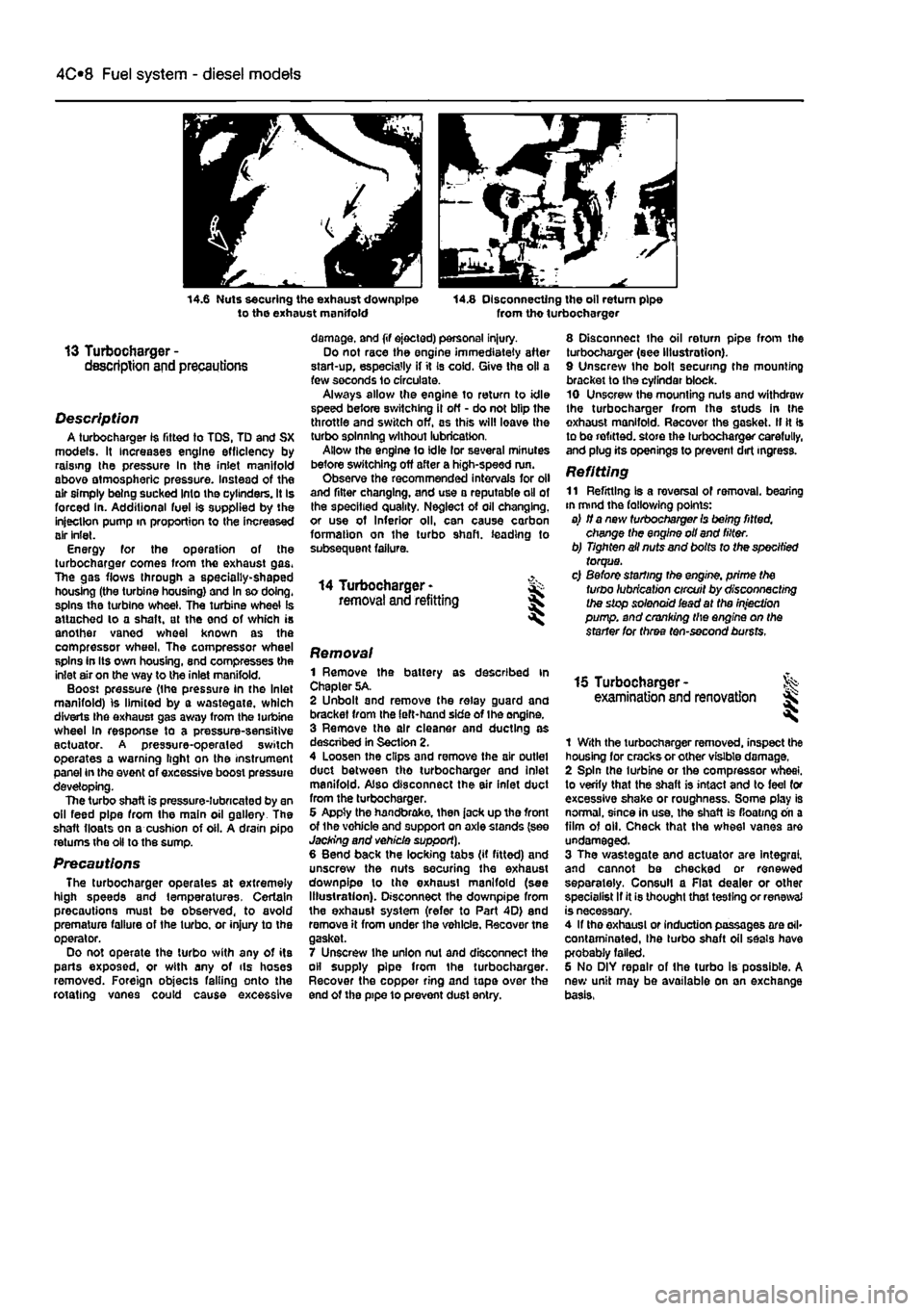
14.6 Nuts securing the exhaust downpipe to the exhaust manifold 14.8 Disconnecting the oil return pipe from tho turbocharger
13 Turbocharger -description and precautions
Description A turbocharger 1$ fitted to TDS, TD and SX models. It increases engine efficiency by raising the pressure In the inlet manifold above atmospheric pressure. Instead of the air simply being sucked Into the cylinders. It Is forced in. Additional fuel is supplied by the injection pump in proportion to the increased air inlet. Energy for the operation of the turbocharger comes from the exhaust gas. The gas flows through a specially-shaped housing (the turbine housing) and In so doing, spins the turbine wheel. The turbine wheel is attached lo a shaft, at the end of which is another vaned wheel known as the compressor wheel, The compressor wheel spins in Its own housing, snd compresses the inlet air on the way to the inlet manifold. Boost pressure (the pressure in the Inlet manifold) is limited by a wastegate, which diverts Ihe exhaust gas away from the turbine wheel In response to a pressure-sensitive actuator. A pressure-operaled switch operates a warning light on the instrument panel in the event of excessive boost pressure developing. The turbo shaft is pressure-lubricated by an oil feed pipe from the main oil gallery The shaft floats on a cushion of oil. A drain pipo returns the oil to the sump.
Precautions The turbocharger operates at extremely high speeds and temperatures. Certain precautions must be observed, to avoid premature failure of the turbo, or injury to the operator. Do not operate the turbo with any of its parts exposed, or with any of ils hoses removed. Foreign objects falling onto the rotating vanes could cause excessive
damage, and (if ejected) personal injury. Do not race the engine immediately after start-up, especially if it Is cold. Give the oil a few seconds lo circulate. Always allow the engine to return to idle speed before switching il off - do not blip the throttle and switch off, as this will leave the turbo spinning without lubrication. Allow the engine to idle lor several minutes before switching off after a high-speed run. Observe the recommended intervals for oil and filter changing, and use a reputable oil of the specified quality. Neglect of oil changing, or use of Inferior oil, can cause carbon formation on the turbo shaft, leading to subsequent failure.
14 Turbocharger -removal and refitting
8 Disconnect the oil return pipe from the turbocharger (see Illustration). 9 Unscrew the bolt securing the mounting bracket to the cyfindar block. 10 Unscrew the mounting nuts and withdraw the turbocharger from the studs in Ihe exhaust manifold. Recover the gasket. II It Is to be refitted, store the turbocharger carefully, and plug its openings to prevent dirt ingress.
Refitting 11 Refitting Is a reversal of removal, bearing in mind the fallowing points: a) if a new turbocharger Is being fitted, change the engine oil and filter. b) Tighten ail nuts and bolts to the specified torque. c) Before starting the engine, prime the turbo lubrication circuit by disconnecting the stop solenoid iead at the injection pump, and cranking the engine on the starter for three ten-second bursts.
Removal 1 Remove the battery as described in Chapter 5A. 2 Unbolt and remove the relay guard and bracket from the left-hand side of Ihe engine. 3 Remove the air cleaner and ducting as descnbed in Section 2. 4 Loosen the clips and remove the air outlet duct between tho turbocharger and inlet manifold. Also disconnect the air inlet duct from the turbocharger. 6 Appty the handbrake, then jack up tho front of the vohicle and support on axle stands (see Jacking and vehicle support). 6 Bend back the locking tabs (if fitted) and unscrew the nuts securing the exhaust downpipe lo the exhaust manifold (see Illustration). Disconnect the downpipe from the exhaust system (refer to Part 4D) end remove it from under the vehicle. Recover tne gasket. 7 Unscrew ihe union nut and disconnect the oil supply pipe from the turbocharger. Recover the copper ring and tape over the end of the pipe 10 prevent dust entry.
15 Turbocharger -examination and renovation l
1 With the turbocharger removed, inspect the housing for cracks or other visible damage. 2 Spin the turbine or the compressor wheel, to verify that the shaft is intact and to feel for excessive shake or roughness. Some play is normal, since in use, the shaft is floating on a film of oil. Check that the wheel vanes are undamaged. 3 The wastegate and actuator are Integral, and cannot be checked or renewed separately. Consul! a Flat dealer or other specialist If it is thought that testing or renewal is necessary. 4 If tho exhaust or induction passages are ail* contaminated, Ihe turbo shaft oil seals have probably failed. 6 No DIY repair of the turbo is possible. A new unit may be available on an exchange basis,
Page 150 of 225
5A«2 Starting and charging systems
Maintenance-free battery -charging Note: The following is intended as a guide only. Always refer to the manufacturer's recommendations (often printed on a label attached to the battery) before charging a battery. 13 This battery type takes considerably longer lo fully recharge than the standard type, the time taken being dependent on the extent of discharge, but it can take anything
up
to three days. 14 A constant voltage type charger is required, tooe set, when connected, to 13.9 to 14.9 votts wth a charger current below 25 amps. Using
mis
method, the battery should be usable within three hours, giving a voltage reading of 12.5 vofts. but this Is for a partially discharged battery and, as mentioned, full charging can
take
considerably longer. 15 If Ihe battery is to be charged from a fully discharged state {condition reading loss lhan 12.2 volts), have it recharged by your FIAT dealer or local automotive electrician, as Ihe charge rate is higher and constant super-vision during charging Is necessary.
3 Battery -removal and refitting
Note: Refer to Disconnecting the battery in ifte Reference Section of this manual before proceeding.
Removal 1 Slacken the clamp bolts and disconnect the ctamp from the battery negative (earth) terminal. 2 Remove the insulation cover (where fitted)
and
disconnect the positive terminal lead(s) in
Die same
way. 3 At the base of the battery, unscrew the bolt from the battery holding clamp plate and remove the clamp plate (see Illustration). A Remove the battery from Ihe engine compartment. 5 II necessary the mounting tray may be removed by unscrewing the bolts. On diesel models it will be necessary to remove the relay guard bolts as well.
Refitting 6 Refitting is a reversal of removal but make sure that the positive terminal is connected first followed by the negative terminal.
4 Alternator/charging system - >%•> testing in vehicle
Note: Refer to the warnings given in Safety first! and in Section 1 of this Chapter before starting work. 1 If the ignition warning light fails to Illuminate when the ignition is switched on, first check the alternator wiring connections for security. If satisfactory, check that the warning light bulb has not blown, and that the bulbholder is secure in its location in the instrument panel. If the light still fails to illuminate, check the continuity of the warning light feed wire from the alternator to the bulbholder. If all is satisfactory, the alternator is at fault and should be renewed or taken to an auto-electrician for testing and repair. 2 If the ignition warning light Illuminates when the engine Is running, stop the engine and check that the drivebelt is correctly tensioned (see Chapter 1A or 18) and that the alternator connections are secure. If all is so far satisfactory, have the alternator checked by an auto-electrician. 3 If the alternator output is suspect even though the warning light functions correctly, the regulated voltage may be checked as follows. 4 Connect a voltmeter across the battery terminals and start the engine. 5 Increase the engine speed until the voltmeter reading remains steady; the reading should be approximately 12 to 13 volts, and no more than 14 volts. 6 Switch on as many electrical accessories (eg. the headlights, heated rear window and heater blower) as possible, and check that the alternator maintains the regulated voltage at around 13 to 14 volts. 7 If ihe regulated voltage is not as stated, the fault may be due to worn brushes, weak brush springs, e faulty voltage regulator, a faulty diode, a severed phase winding or worn or damaged slip rings. The alternator should be renewed or taken to an auto-electrician for testing and repair.
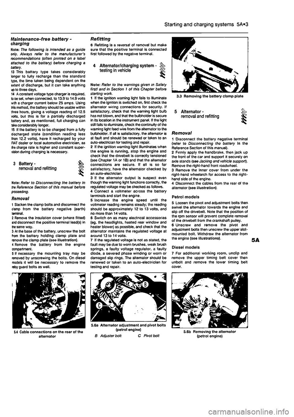
3.3 Removing the battery clamp plate
5 Alternator -removal and refitting
Removal 1 Disconnect the battery negative terminal {refer to Disconnecting the battery In the Reference Section of this manual). 2 Firmly apply the handbrake, then jack up the front of the car and support it securely on axle stands (see Jacking and vehicle support). Remove tho right-hand front roadwheel. 3 Remove Ihe Inner cover from under the right-hand wheelarch for access to tho right-hand side of the engine. 4 Disconnect the cables from the rear Of the alternator (see illustration).
Petrol models 5 Loosen the pivot and adjustment bolts then swivel the alternator towards the engine and slip off the drivebelt. Note that the position of the rpm sensor will prevent complete removal of the drivebelt from the crankshaft puiley. 6 Unscrew and remove the pivot and adjustment bolts then unscrew the upper slot-mounted bolt. Withdraw the alternator from the engine (see illustrations).
Diesel models 7 For additional working room, unclip and remove the upper timing belt cover then unbolt and remove the lower timing belt cover.
5.4 Cable connections on the rear of the alternator
5.6a Alternator adjustment and pivot bolts (petrol engine) B Adjuster bolt C Pivot bolt 5.6b Removing the alternator (petrol engine)
Page 212 of 225
Bodywork and fittings
11
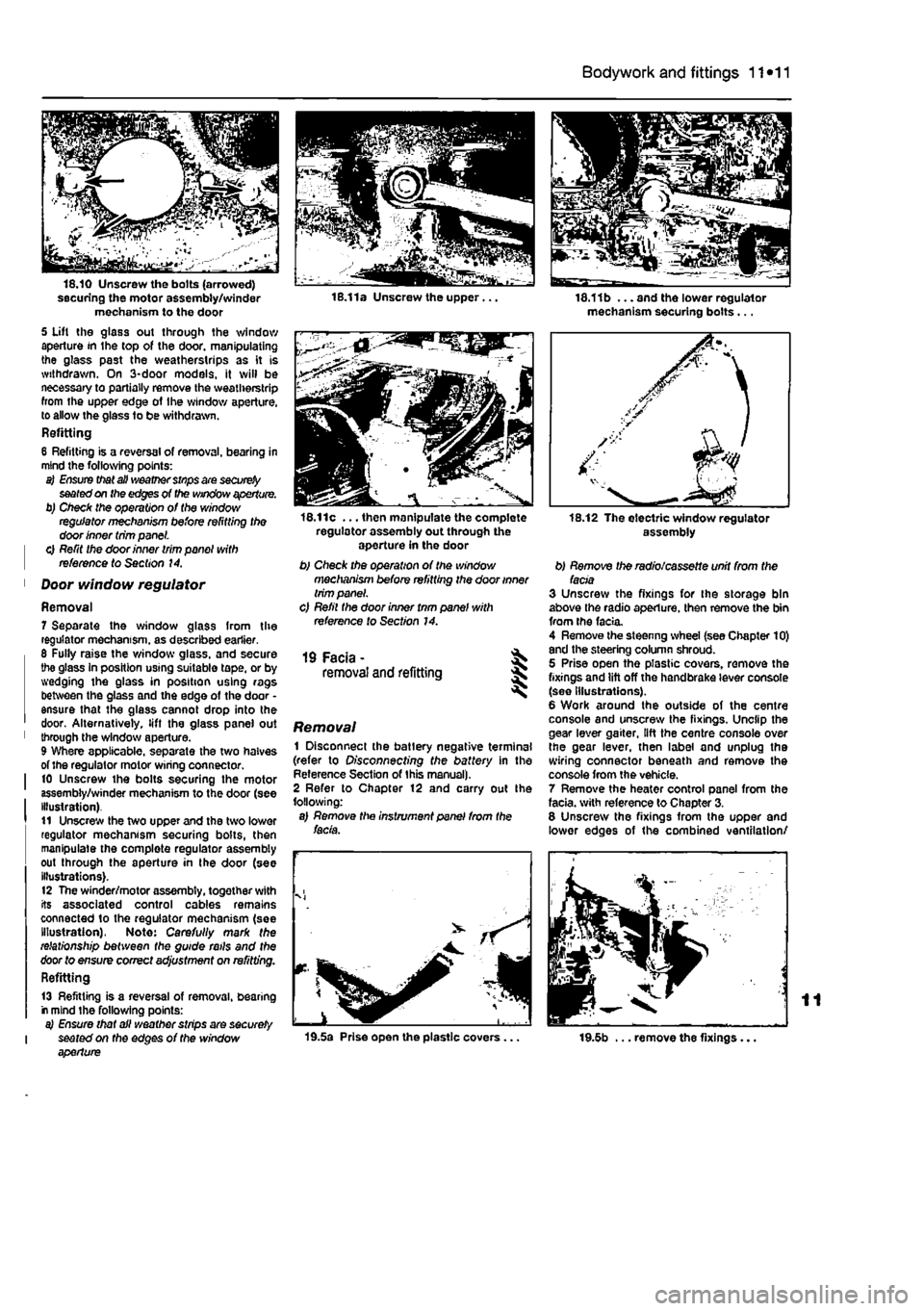
*11
securing the motor assembly/winder mechanism to the door 5 Uft the glass out through the window aperture in the top of the door, manipulating the glass past the weatherstrips as it is withdrawn. On 3-door models, it will be necessary to partially remove the weatherstrip from the upper edge of Ihe window aperture, to allow the glass to be withdrawn. Refitting 6 Refitting is a reversal of removal, bearing in mind the following points: a) Ensure that all weather stnps are
securely
seated on the edges of the window aperture. b) Check the operation of the window regulator mechanism before refitting the door inner trim panel. | 0 Refit the door inner trim panel with | reference to Section 14.
1 Door window regulator
Removal 7 Separate the window glass from the regulator mechanism, as described earlier. 6 Fully raise the window glass, and secure the glass In position using suitable tape, or by wedging the glass in position using rags between the glass and the edge of the door • ensure that the glass cannot drop into the door. Alternatively, lift the glass panel out 1 through the window aperture. 9 Where applicable, separate the two halves of the regulator motor wiring connector. I 10 Unscrew the bolts securing the motor assembly/winder mechanism to the door (see Illustration). t1 Unscrew the two upper and the two lower regulator mechanism securing bolts, then manipulate the complete regulator assembly out through the aperture in the door (see illustrations). 12 The winder/motor assembly, together with its associated control cables remains connected to the regulator mechanism (see Illustration), Note: Carefully mark the relationship between the guide rails and the door to ensure correct adjustment on refitting. Refitting
13 Refitting is a reversal of removal, bearing r mind the following points: a) Ensure that all weather strips are securely I seated on the edges of the window aperture
16.11c ... then manipulate the complete regulator assembly out through the aperture in the door b) Check the operation of the window mechanism before refitting the door inner trim panel. c) Refil the door inner tnm panel with reference to Section 14.
19 Facia - ^ removal and refitting 5
Removal 1 Disconnect the batlery negative terminal (refer to Disconnecting the battery in the Reference Section of this manual). 2 Refer to Chapter 12 and carry out Ihe following: a) Remove the instrument panel from the facia.
19.5a Prise open the plastic covers...
18.11b ... and the lower regulator mechanism securing bolts...
assembly
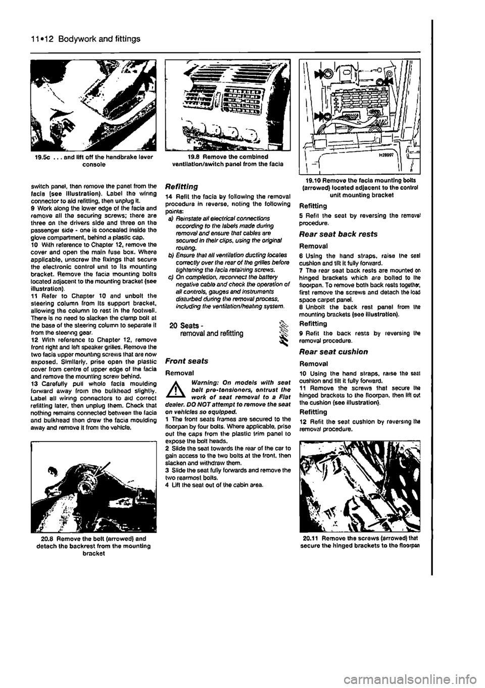
b) Remove the radio/cassette unit from the facia 3 Unscrew the fixings for the storage bin above the radio aperture, then remove the bin from the facia. 4 Remove the steenng wheel (see Chapter 10) and the steering column shroud. 5 Prise open the plastic covers, remove the fixings and lift off the handbrake lever console (see Illustrations). 6 Work around the outside of the centre console and unscrew the fixings. Unclip the gear lever gaiter, lift the centre console over the gear lever, then label and unplug the wiring connector beneath and remove the console from the vehicle. 7 Remove the heater control panel from the facia, with reference to Chapter 3. 8 Unscrew the fixings from the upper and lower edges of the combined ventilation/
19.5b ... remove the fixings...
Page 213 of 225
11 *12 Bodywork and fittings
switch panel, then remove the panel from the facia (see illustration). Label tho wiring connector to aid refitting, then unplug It. 0 Work along the lower edge of Ihe facia and remove all the securing screws; there are three on the drivers side and three on the passenger side - one is concealed inside the glove compartment, behind a plastic cap. 10 Wilh reference to Chapter 12, remove the cover and open the main fuse box. Where applicable, unscrew the fixings that secure the electronic control unit to Its mounting bracket. Remove the facia mounting bolts located adjacent to the mounting bracket (see illustration). 11 Refer to Chapter 10 and unbolt the steering column from Its support bracket, allowing the column to rest in the footwell. There is no need to slacken the clamp bolt at Ihe base of the steering column to separate it from the steering gear. 12 With reference to Chapter 12, remove front right and left speaker grilles. Remove the two facis upper mounting screws ihat are now exposed. Similarly, prise open the plastic cover from centre of upper edge of the fada and remove the mounting screw behind. 13 Carefully pull whole facia moulding forward away from tho bulkhead slightly. Label all wiring connectors to aid correct refitting later, then unplug Ihem. Check that nothing remains connected between the facia and bulkhead then draw the facia moulding away and remove It from the vehicle.
20.8 Remove the bolt (arrowed) and detach the backrest from the mounting bracket
Refitting 14 Refit the facia by following the removal procedure in reverse, noting the following points: a) Reinstate all electrical connections according to (he labels made during removal and ensure that cables are secured in their clips, using the origins/ routing. b) Ensure thai all ventilation ducting locates correctly over the rear of the grilles before tightening the facia retaining screws. c) On completion, reconnect the battery negative cable and chock the operation of all controls, gauges and Instruments disturbed during the removal process, Including the ventilation/heating system.
20 Seats -removal and refitting JS:
Front seats
Removal
A
Warning: On models with seat belt pre-tonsionors, entrust the work of seat removal to a Flat dealer. DQNOTattempt to remove the seat on vehicles so equipped. 1 The front seats frames are secured to the fioorpan by four bolts. Whero applicable, prise out the caps from the plastic trim panel lo expose the bolt heads. 2 Slide the seat towards the rear of the car to gain access to the two bolts at the front, Ihen slacken and withdraw them. 3 Slide Ihe seat fully forwards and remove the two rearmost bolls. 4 Ufl the seat out of the cabin area.
(arrowed) located adjacent to the control unit mounting bracket Refitting 5 Refil the seat by reversing the remove! procedure. Rear seat back rests
Removal 6 Using the hand straps, raise the seal cushion and lilt it fully forward. 7 The rear seat back rests are mounted or hinged brackets which aro boiled to Ihe fioorpan. To remove both back rests together, first remove the screws and detach the load space carpet panel. 8 Unbolt the back rest panel from the mounting brackets (see illustration). Refitting 9 Refit tho back rests by reversing Ihe removal procedure. Rear seat cushion
Removal 10 Using the hand straps, raise the seat cushion and tilt it fully forward. 11 Remove ihe screws Ihat secure Ihe hinged brackets to tho fioorpan. then lift out the cushion (see illustration}. Refitting 12 Refit the seat cushion by reversing Ihe removal procedure.
20.11 Remove the screws (arrowed) that secure the hinged brackets to the fioorpan
Page 214 of 225
10*1
Chapter 12
Body electrical systems
Contents
Bulbs (exterior lights) - renewal 4 Bulbs (interior lights) - renewal 5 Electrical fault finding - general information 2 Exterior light units - removal and refitting 6 Fuses and relays - general Information 3 General information and precautions 1 Headlight beam alignment • general Information 6 Horn • removal and refitting 9 Instrument panel - removal and refitting 7 Loudspeakers - removal and refitting 10
Degrees of difficulty
Radio aerial - removal and refitting 11 Radio/cassette player • removal and refitting 12 Speedometer drive cable - removal and refitting 13 Switches - removal end refitting 14 Tailgate wiper motor - removal and refitting 15 Windscreen wiper motor - removal and refitting 17 Windscreen/tailgate washer system components • removal and refitting 16 Wiper arm • removal and refitting 18
Easy,
statable for ^
novice with liffle
|| experience ^
Fairly
easy,
suitable for beginner with ^ some experience ^
Fabtycffficiit,
suitable
for competent ^
DIY
mechanic ^
Difficult, suitable for
^ experienced DIY JR mechanic
Very difficult,
A,
suitable
for
expert DIY
Sj or professional ^
Specifications
Bulb ratings Watts Headlights 60/55 Front long range driving light 55 Front fogllght 55 Front direction Indicator light 21 Front sidelight 5 Front direction indicator repeater light 5 Stop light 21 Tall light 5 Rear direction indicator light 21 Reversing light 21 near fogllght 21 Hear number plate light 5 Courtesy light 10 Map reading light 5
1 Genera! information and precautions
A
Warning: fie/Ore carrying out any work on the electrical system, read through the precautions given in Safety first! at the beginning of this manual, and in Chapter 8. The electrical system is of 12-volt negative earth type. Power for the lights and all electrical accessories is supplied by a lead/acid type battery, which is charged by the alternator. This Chapter covers repair and service procedures for the various electrical components not associated with the engine. Information on the battery, alternator and starter motor can be found in Chapter 5. It should be noted that, prior to working on any component In the electrical system, the
battery negative terminal should first be disconnected, to prevent the possibility of electrical short-circuits and/or fires. Caution: Before proceeding, refer to Disconnecting the battery In the Reference Section of this manual for further information.
2 Electrical fault finding-general information
Note: Refer to the precautions given In Safety first! and in Section 1 of this Chapter before starting work. The following tests relate to testing ot the main electrical circuits, and should not be used to test delicate electronic circuits (such as antHock braking systems), particularly where an electronic con fro/ module is used.
General 1 A typical electrical circuit consists of an electrical component, any switches, relays, motors, fuses, fusible links or circuit breakers related to that component, and the wiring and connectors which link the component to both the battery and the chassis. To help to pinpoint a problem in an electrical circuit, wiring diagrams are Included at the end of this manual. 2 Before attempting to diagnose an electrical fault, first study the appropriate wiring diagram, to obtain a more complete understanding of the components included In the particular circuit concerned. The possible sources of a fault can be narrowed down by noting whether other components related to the circuit are operating properly. If several components or circuits fait at one time, the problem Is likely to be related to a shared fuse or earth connection.