jack points FIAT PUNTO 1995 176 / 1.G Workshop Manual
[x] Cancel search | Manufacturer: FIAT, Model Year: 1995, Model line: PUNTO, Model: FIAT PUNTO 1995 176 / 1.GPages: 225, PDF Size: 18.54 MB
Page 6 of 225
Safety first! 0.5
Working on your ear can be dangerous. This page shows just some of the potential risks and hazards, with the aim of creating a safety-conscious attitude.
General hazards
Scalding • Don't remove the radiator or expansion tank cap while the engine is hot. • Engine oil, automatic transmission fluid or power steering fluid may also be dangerously hot if the engine has recently been running.
Burning • Beware of burns from the exhau3t system and from any part of the engine. Brake discs and drums can also be extremely hot immediately after use.
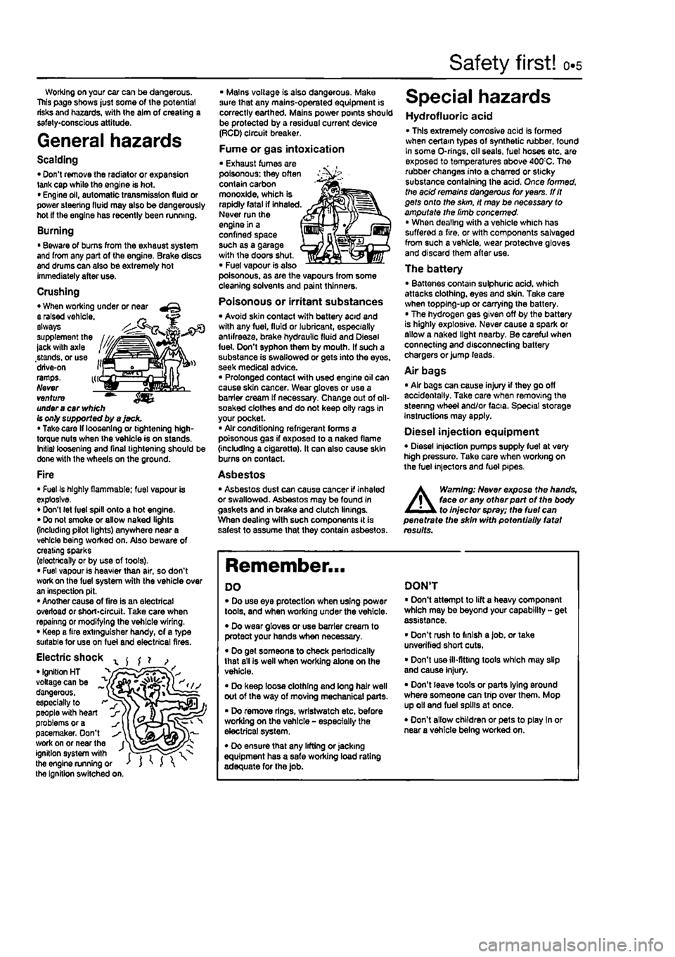
Crushing • When working under or near a raised vehicle. ~ always supplement the ' ' -jack with axle stands, or use ... drive-on i'j ramps. kr Never venture ™ under
a
car
vv/j/ch
Is only supported by a jack. • Take card if loosening or tightening high-torque nuts when the vehicle is on stands. Initial loosening and final tightening should be done with the wheels on the ground.
Fire • Fuel Is highly flammable; fuel vapour is explosive. • Don't (et fuel spill onto a hot engine. • Do not smoke or allow naked lights (including pilot lights) anywhere near a vehicle being worked on. Also beware of creating sparks (electrically or by use of toots). • Fuel vapour is heavier than air, so don't work on the fuel system with the vehicle over an inspection pit. • Another cause of fire is an electrical overload or short-circuit. Take care when repainng or modifying the vehicle wiring. • Keep a fire extinguisher handy, of a type suitable for use on fuel and electrical fires.
Electric shock x ^ ^ ? , • Ignition HT _ " voltage can be ^ dangerous, ~ especially to > people with heart problems or a pacemaker. Don't work on or near the f^ ignition system with fT") the engine running or ' J ' J the Ignition switched on.
• Mains voltage is also dangerous. Make sure that any mains-operated equipment is correctly earthed. Mains power points should be protected by a residual current device (RCD) circuit breaker.
Fume or gas intoxication • Exhaust fumes are poisonous: they often contain carbon monoxide, which is rapidly fatal if inhaled. Never run the engine in a confined space such as a garage with the doors shut, • Fuel vapour is also poisonous, as are the vapours from some cleaning solvents and paint thinners.
Poisonous or irritant substances • Avoid skin contact with battery acid and with any fuel, fluid or lubricant, especially antifreeze, brake hydraulic fluid and Diesel fuel. Don't syphon them by mouth. If such a substance is swallowed or gets into the eyes, seek medical advice. « Prolonged contact with used engine oil can cause skin cancer. Wear gloves or use a barrier cream If necessary. Change out of oll-soaked clothes and do not keep oily rags in your pocket. • Air conditioning refrigerant forms a poisonous gas if exposed to a naked flame {including a cigarette). It can also cause skin burns on contact.
Asbestos • Asbestos dust can cause cancer if inhaled or swallowed. Asbestos may be found In gaskets and in brake and clutch linings. When dealing with soch components It is safest to assume that they contain asbestos.
Special hazards
Hydrofluoric acid • This extremely corrosive acid is formed when cerlam types of synthetic rubber, found In some O-rings, oil seals, fuel hoses etc. are exposed to temperatures above 400;C. The rubber changes into a charred or sticky substance containing the acid. Once formed, the acid remains dangerous for years, tfit gets onto the skin, it may be necessary to amputate the limb concerned. • When dealing with a vehicle which has suffered a fire, or with components salvaged from such a vehicle, wear protective gloves and discard them after use.
The battery • Batteries contain sulphuric acid, which attacks clothing, eyes and skin. Take care when topping-up or carrying the battery. • The hydrogen gas given off by the battery is highly explosive. Never cause a spark or allow a naked light nearby. Be careful when connecting and disconnecting battery chargers or jump leads.
Air bags • Air bags can cause injury if they go off accidentally. Take care when removing the steenng wheel and/or facia. Special storage instructions may apply.
Diesel injection equipment • Diesel injection pumps supply fuel at very high pressure. Take care when working on the fuel injectors and fuel pipes.
A
Warning: Never expose the hands, face or any otfterpart of the body to injector spray; the fuel can penetrate the skin with potentially fatal results.
Remember...
DO • Do use eye protection when using power tools, and when working under the vehicle. • Do wear gloves or use barrier cream to protect your hands when necessary. • Do get someone to check periodically that all is well when working alone on the vehicle. • Do keep loose clothing and long hair well out of the way of moving mechanical parts. • Do remove rings, wrtstwatch etc. before working on the vehicle - especially the electrical system, • Do ensure that any lifting or jacking equipment has a safe working load rating adequate for the job.
DON'T • Don't attempt to lift a heavy component which may be beyond your capability - get assistance. • Don't rush to finish a job. or take unverified short cuts. • Don't use ill-fitting toots which may slip and cause injury. • Don't leave tools or parts lying around where someone can trip over them. Mop up oil and fuel spills at once. • Don't allow children or pets to play In or near a vehicle being worked on.
Page 143 of 225
Fuel system - diesel models 4C*3
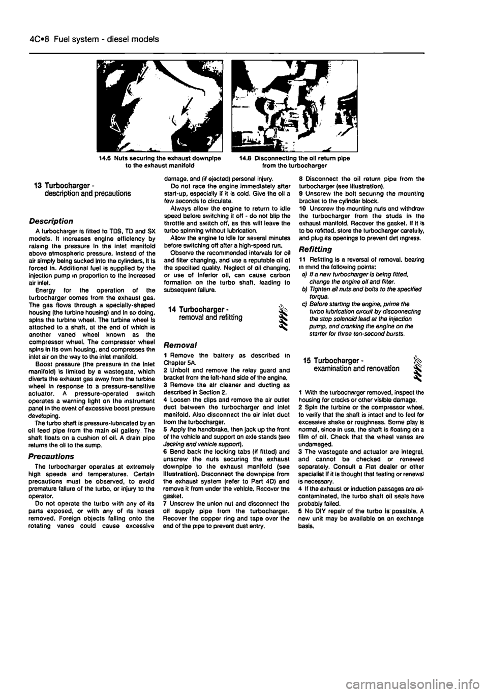
14.6 Nuts securing the exhaust downpipe to the exhaust manifold 14.8 Disconnecting the oil return pipe from tho turbocharger
13 Turbocharger -description and precautions
Description A turbocharger 1$ fitted to TDS, TD and SX models. It increases engine efficiency by raising the pressure In the inlet manifold above atmospheric pressure. Instead of the air simply being sucked Into the cylinders. It Is forced in. Additional fuel is supplied by the injection pump in proportion to the increased air inlet. Energy for the operation of the turbocharger comes from the exhaust gas. The gas flows through a specially-shaped housing (the turbine housing) and In so doing, spins the turbine wheel. The turbine wheel is attached lo a shaft, at the end of which is another vaned wheel known as the compressor wheel, The compressor wheel spins in Its own housing, snd compresses the inlet air on the way to the inlet manifold. Boost pressure (the pressure in the Inlet manifold) is limited by a wastegate, which diverts Ihe exhaust gas away from the turbine wheel In response to a pressure-sensitive actuator. A pressure-operaled switch operates a warning light on the instrument panel in the event of excessive boost pressure developing. The turbo shaft is pressure-lubricated by an oil feed pipe from the main oil gallery The shaft floats on a cushion of oil. A drain pipo returns the oil to the sump.
Precautions The turbocharger operates at extremely high speeds and temperatures. Certain precautions must be observed, to avoid premature failure of the turbo, or injury to the operator. Do not operate the turbo with any of its parts exposed, or with any of ils hoses removed. Foreign objects falling onto the rotating vanes could cause excessive
damage, and (if ejected) personal injury. Do not race the engine immediately after start-up, especially if it Is cold. Give the oil a few seconds lo circulate. Always allow the engine to return to idle speed before switching il off - do not blip the throttle and switch off, as this will leave the turbo spinning without lubrication. Allow the engine to idle lor several minutes before switching off after a high-speed run. Observe the recommended intervals for oil and filter changing, and use a reputable oil of the specified quality. Neglect of oil changing, or use of Inferior oil, can cause carbon formation on the turbo shaft, leading to subsequent failure.
14 Turbocharger -removal and refitting
8 Disconnect the oil return pipe from the turbocharger (see Illustration). 9 Unscrew the bolt securing the mounting bracket to the cyfindar block. 10 Unscrew the mounting nuts and withdraw the turbocharger from the studs in Ihe exhaust manifold. Recover the gasket. II It Is to be refitted, store the turbocharger carefully, and plug its openings to prevent dirt ingress.
Refitting 11 Refitting Is a reversal of removal, bearing in mind the fallowing points: a) if a new turbocharger Is being fitted, change the engine oil and filter. b) Tighten ail nuts and bolts to the specified torque. c) Before starting the engine, prime the turbo lubrication circuit by disconnecting the stop solenoid iead at the injection pump, and cranking the engine on the starter for three ten-second bursts.
Removal 1 Remove the battery as described in Chapter 5A. 2 Unbolt and remove the relay guard and bracket from the left-hand side of Ihe engine. 3 Remove the air cleaner and ducting as descnbed in Section 2. 4 Loosen the clips and remove the air outlet duct between tho turbocharger and inlet manifold. Also disconnect the air inlet duct from the turbocharger. 6 Appty the handbrake, then jack up tho front of the vohicle and support on axle stands (see Jacking and vehicle support). 6 Bend back the locking tabs (if fitted) and unscrew the nuts securing the exhaust downpipe lo the exhaust manifold (see Illustration). Disconnect the downpipe from the exhaust system (refer to Part 4D) end remove it from under the vehicle. Recover tne gasket. 7 Unscrew ihe union nut and disconnect the oil supply pipe from the turbocharger. Recover the copper ring and tape over the end of the pipe 10 prevent dust entry.
15 Turbocharger -examination and renovation l
1 With the turbocharger removed, inspect the housing for cracks or other visible damage. 2 Spin the turbine or the compressor wheel, to verify that the shaft is intact and to feel for excessive shake or roughness. Some play is normal, since in use, the shaft is floating on a film of oil. Check that the wheel vanes are undamaged. 3 The wastegate and actuator are Integral, and cannot be checked or renewed separately. Consul! a Flat dealer or other specialist If it is thought that testing or renewal is necessary. 4 If tho exhaust or induction passages are ail* contaminated, Ihe turbo shaft oil seals have probably failed. 6 No DIY repair of the turbo is possible. A new unit may be available on an exchange basis,
Page 146 of 225
4D*3 Exhaust and emission control systems
Refitting 8 Refitting is a reversal of the removal pro-cedure but fit new gaskets. Tighten the nuts lo the specified torque.
Diesel models Note: On diesel models the inlet and exhaust
manifolds
are located on the rear of the engine
end
share the same securing nuts and gasket. Removal 8 Remove the inlet manifold as described In Part
C
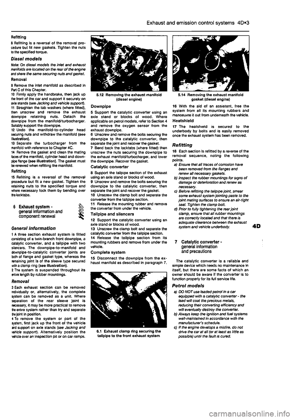
of this Chapter. 10 Firmly apply the handbrake, then jack up lite front of tho car and support it securely on axle stands (see Jacking and vehicle support). 11 Straighten the tab washers (where fitted), then unscrew and remove the exhaust downpipe retaining nuts. Detach the downpipe from the manifold/turbocharger. Suitably support the downpipe. 12 Undo the manifold-to-cylinder head securing nuts and withdraw the manifold (see Illustration). 13 Separate the turbocharger from the manifold with reference to Chapter 4C. 14 Remove the gasket and clean the mating
(aces
of the manifold, cylinder head and down-pipe flange (see illustration). The gasket must
be
renewed when refitting the manifold, Refitting
15 Refitting is a reversal of the removal procedure but fit a new gasket. Tighten the retaining nuts to the specified torque and where necessary lock them by bending over
the
tocktabs.
6 Exhaust system - % general information and ^ component renewal
Genera/ Information 1 A three section exhaust system is fitted consisting of a twin-branch front downpipe, a catalytic converter, and a tailpipe with two silencers. The downpipe-to-manifold and downpipe-to-catalytic converter joints are both of flange and gasket type, whereas the remaining joint Is of the sleeve type secured
witn
a clamp ring (see illustration). 2 The system is suspended throughout its entire length by rubber mountings.
Removal 3 Each exhaust section can be removed individually or, alternatively, the complete system can be removed as a unit. Where separation of the rear sleeve Joint is necessary, it may be more practical to remove
the
entire system rather than try and separate
the Joint
In position. 4 To remove the system or part of the system, first jack up the front of the vehicle and support on axle stands (see Jacking and nhlcle support), Alternatively position the
vehicle
over an inspection pit or on car ramps.
5.12 Removing the exhaust manifold (diesel engine) Downpipe 5 Support the catalytic converter using an axle stand or blocks of wood. Where applicable on petrol models, refer to Section 4 and remove the oxygen sensor from the exhaust downpipe. 6 Unscrew and remove the bolts securing the downpipe to tha catalytic converter, then separate the joint and recover the gasket. 7 Bend back the locktabs (where fitted) then unscrew the nuts securing the downpipe to the exhaust manifold/turbocharger. and lower the downpipe, Recover the gasket. Catalytic converter
8 Support the tailpipe section of the exhaust using an axle stand or blocks of wood. 9 Unscrew and remove the bolts securing the downpipe to the catalytic converter, then separate the joint and recover the gasket. 10 Unscrew the clamp bolt and separate the converter from the tailpipe section. 11 Release the mounting rubber and remove the converter from under the vehicle. Tailpipe and silencers 12 Support the catalytic converter using an axle stand or blocks of wood. 13 Unscrew the clamp bolt and separate the catalytic converter from the tailpipe section. 14 Release the tailpipe section from its mounting rubbers and remove from under the vehicle. Complete system 15 Disconnect the downpipe from the ex-haust manifold as described in paragraph 7.
6.1 Exhaust clamp ring securing the tailpipe to the front exhaust system
5.14 Removing the oxhaust manifold gasket (diesel engine) 16 With the aid of an assistant, free the system from all its mounting rubbers and manoeuvre it out from underneath the vehicle. Heatshield 17 The heatshield is secured to the underbody by bolts and Is easily removed once the exhaust system has been removed.
Refitting 18 Each section is refitted by a reverse of the removal sequence, noting the following points. a) Ensure that all traces of corrosion have been removed from the flanges and renew ail necessary gaskets. b) Inspect the rubber mountings for signs of damage or deterioru tion and renew
as
necessary. c) Before refitting the tailpipe joint, smear some exhaust system jointing paste to the joint mating surfaces to ensure an air-tight seal. Tighten the clamp bolt. d) Prior to fully tightening the rear joint damp, ensure that all rubber mountings are correctly /ocafed and that there is adequate clearance between the exhaust system and vehicle underbody.
7 Catalytic converter -general information and precautions
The catalytic converter is a reliable and simple device which needs no maintenance In itself, but there are some facts of which an owner should be aware if the converter is to function properly for its full service life.
Petrol models a) DO NOT use leaded petrot In a car equipped with a catalytic converter - Ihe lead will coat the precious metals, redudng their converting efficiency
and
will eventually destroy the converter. b) Always keep the ignition and fuel systems well-maintained in accordance with the manufacturer's schedule. c) If the engine develops a misfire, do not drive the car at all (or at least as little
as
possible) until the fault is cured.
Page 164 of 225
Manual transmission 7A*3
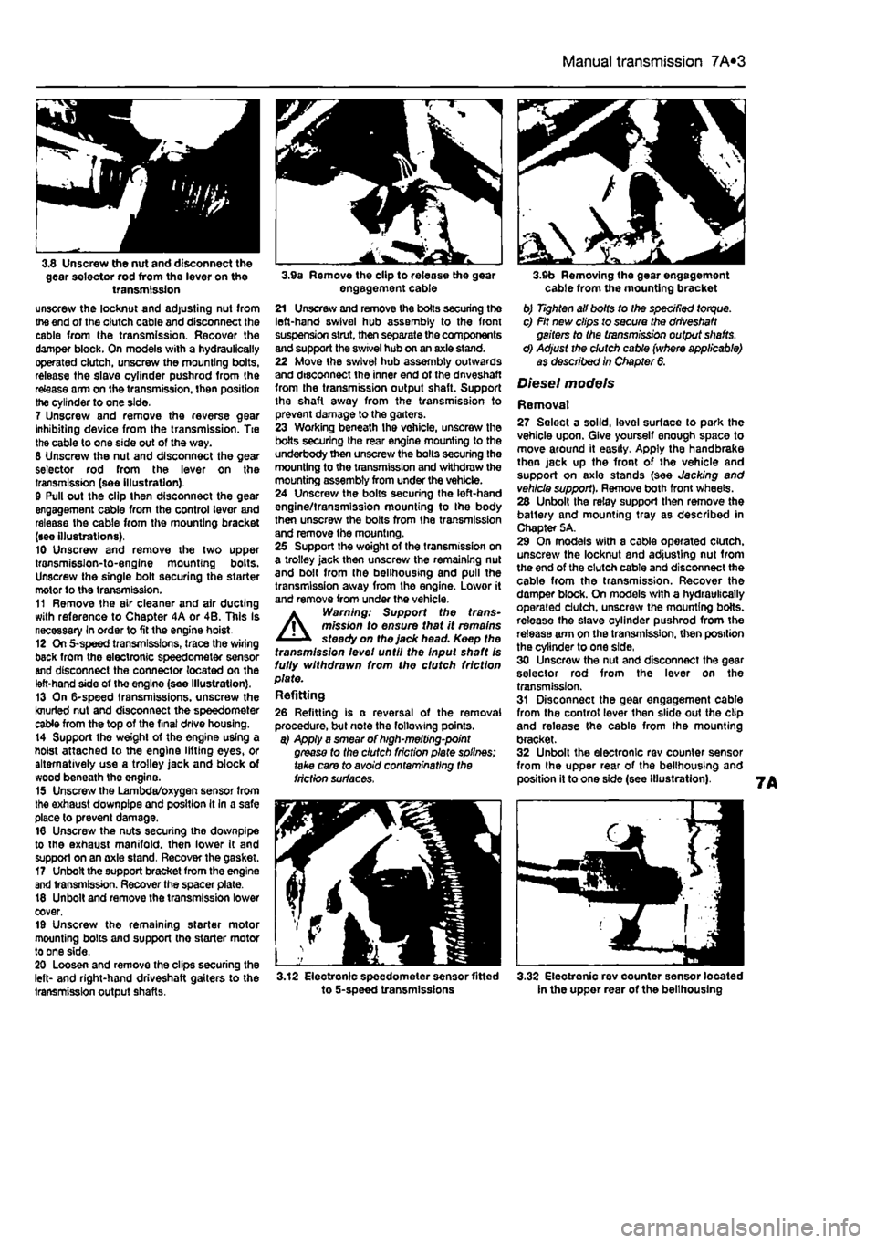
3,8 Unscrew the nut and disconnect the gear selector rod from the lever on the transmission unscrew the locknut and adjusting nut from the end of the clutch cable and disconnect the cable from the transmission. Recover the damper block. On models with a hydraulically operated clutch, unscrew the mounting bolts, release the slave cylinder pushrod from the re&ase arm on the transmission, then position the cylinder to one side.
7 Unscrew and remove the reverse gear Inhibiting device from the transmission. Tie the cable to one side out of the way. 8 Unscrew the nut and disconnect the gear selector rod from the lever on the transmission (see illustration). 9 Pull out the clip then disconnect the gear engagement cable from the control lever and release the cable from the mounting bracket (see illustrations). 10 Unscrew and remove the two upper transmisslon-to-englne mounting bolts. Unscrew the single bolt securing the starter motor to the transmission. 11 Remove the air cleaner and air ducting with reference to Chapter 4A or 4B. This Is necessary In order to fit the engine hoist 12 On 5-speed transmissions, trace the wiring back from the electronic speedometer sensor and disconnect the connector located on the left-hand side of the engine (see illustration). 13 On 6-speed transmissions, unscrew the knurled nut and disconnect the speedometer cable from the top of the final drive housing. 14 Support the weight of the engine using a hoist attached to the engine lifting eyes, or alternatively use a trolley jack and block of wood beneath Ihe engine. 15 Unscrew the Lambda/oxygen sensor from the exhaust downpipe and position It In a safe place to prevent damage. 16 Unscrew the nuts securing the downpipe to the exhaust manifold, then lower It and support on an axle stand. Recover the gasket. 17 Unbolt the support bracket from the engine and transmission. Recover the spacer plate. 18 Unbolt and remove the transmission lower cover, 19 Unscrew the remaining starter motor mounting bolts and support tho starter motor to one side. 20 Loosen and remove the clips securing the left- and right-hand driveshaft gaiters to the transmission output shafts.
3.9a Remove the clip to release the gear engagement cable 21 Unscrew and remove the boils securing the left-hand swivel hub assembly to the front suspension strut, then separate the components and support the swivel hub on an axle stand. 22 Move the swivel hub assembly outwards and disconnect the inner end of the dnveshaft from the transmission output shaft. Support the shaft away from the transmission to prevent damage to the garters. 23 Working beneath the vehicle, unscrew the botts securing the rear engine mounting to the underbody then unscrew the bolts securing the mounting to the transmission and withdraw the mounting assembly from under the vehicle. 24 Unscrew the bolts securing the left-hand engine/transmission mounting to Ihe body then unscrew the bolts from the transmission and remove the mounting. 25 Support the woight of the transmission on a trolley jack then unscrew the remaining nut and bolt from the belihousing and pull the transmission away from the engine. Lower it and remove from under the vehicle. A Warning: Support the trans-mission to ensure that it remains steady on the jack head. Keep the transmission levet until the Input shaft Is fully withdrawn from the clutch friction plate. Refitting
26 Refitting is a reversal of the removal procedure, but note the following points. a) Apply a smear of high-melting-point grease to the clutch friction plate splines; take care to avoid contaminating the friction surfaces.
3.12 Electronic speedometer sensor fitted to 5-speed transmissions
3.9b Removing the gear engagement cable from the mounting bracket b) Tighten all bolts to Ihe specified torque. c) Fit new clips to secure the driveshaft gaiters to the transmission output shafts. d) Adjust the clutch cable (where applicable) as described In Chapter 6.
Diesel models
Removal 27 Seloct a solid, level surface to park the vehicle upon. Give yourself enough space to move around it easily. Apply the handbrake then jack up the front of tho vehicle and support on axlo stands (see Jacking and vehicle support). Remove both front wheels. 28 Unbolt the relay support then remove the batlery and mounting tray as described in Chapter 5A. 29 On models with a cable operated clutch, unscrew the locknut and adjusting nut from the end of the clutch cable and disconnect the cable from the transmission. Recover the damper block. On models with a hydraulically operated clutch, unscrew the mounting botts. release the slave cylinder pushrod from the release arm on the transmission, then position the cylinder to one side, 30 Unscrew the nut and disconnect the gear selector rod from the lever on the transmission. 31 Disconnect the gear engagement cable from the control lever then slide out the clip and release the cable from the mounting bracket. 32 Unbolt the electronic rev counter sensor from the upper rear of the belihousing and position it to one side (see illustration).
3.32 Electronic rev counter sensor located in the upper rear of the belihousing
Page 165 of 225
7A«4 Manual transmission
33 Remove lha air cleaner front section and air ducting with reference to Chapter 4C. Also disconnect the injection pump vacuum pipe from the clips on the left-hand end of the cylinder head. This work is necessary in order to fit the engine hoist 34 Support the weight of the engine using a hoist attached to the engine lifting eyes, or alternatively use a trolley Jack and block of wood beneath the engine. 35 Unscrew the nuts securing the downpipe to the exhaust manifold, then lower it and support on an axle stand. Recover the gasket. 36 Unscrew the starter motor mounting bolts and support the starter motor to one side. 37 Disconnect the wiring from the reversing light switch on the front of the transmission. 38 Unscrew the nut and disconnect the earth cable from its stud. 39 Trace the wiring back from the electronic speedometer sensor and disconnect the connector located on the left-hand side ot the engine. If a mechanical speedometer Is fitted unscrew the knurled collar and disconnect the cabte from the transmission. 40 Unbolt and remove the transmission lower cover. 41 Using an Allen key unscrew the bolts securing the inner end of the left-hand driveshaft to the transmission flange. Remove the bolts and recover the spacer plates. Support the driveshaft on an axle stand. 42 Unscrew and remove the bolts securing the left-hand swivel hub assembly to the front suspension strut, then separate the components and support the swivel hub on an axle stand. 43 Move the swrvel hub assembly outwards and support the driveshaft away from Ihe transmission. 44 Using an Allen key unscrew the bolts securing the Inner end of the right-hand driveshaft to the intermediate shaft flange. Remove the bolts and recover the spacer plates. Support the driveshaft on an axle stand. 45 Remove the intermediate driveshaft with reference to Chapter 8. 46 Working beneath the vehicle, unscrew the bolts securing the rear engine mounting to the underbody then unscrew the bolts securing the mounting to the transmission and withdraw the mounting assembly from under the vehicle.
47 Unscrew the bolts securing the left-hand engine/transmission mounting to the body then unscrew Ihe bolts from the transmission and remove the mounting. 48 Support the weight of the transmission on a trolley jack then unscrew the remaining nut and bolts from the bellhousing and pull the transmission away from the engine.
A
Warning: Support the trans-mission to ensure that It remains steady o/i the jack head. Keep the transmission level until the Input shaft
1$
fully withdrawn from the clutch friction plate.
Refitting 48 Refitting is a reversal of the removal procedure, but note the following points. a) Appiy a smear* of high-meiting-point grease to the clutch friction piate splines; take care to avoid contaminating the friction surfaces. b) Tighten all bolts to the specified torque. c) Fit new clips to secure the driveshaft gaiters to the transmission output shafts. d) Adjust the clutch cable (where applicable) as described In Chapter 6.
4 Manual transmission overhaul -general Infomtatlon
Overhauling a manual transmission is a difficult and Involved Job for the DIY home mechanic. In addition to dismantling and reassembling many small parts, clearances must be precisely measured and, if necessary, changed by selecting shims and spacers. Internal transmission components are also often difficult to obtain, and in many Instances, extremely expensive. Because of this, If the transmission develops a fault or becomes noisy. Ihe best course of action is to have the unit overhauled by a specialist repairer, or to obtain an exchange reconditioned unit. Nevertheless, it is not impossible for the more experienced mechanic to overhaul the transmission, provided the special tools are available, and the Job is done in a deliberate step-by-step manner, so that nothing is overlooked.
The tools necessary for an overhaul include internal and external clrclip pliers, bearing pullers, a slide hammer, a sat of pin punches, a dial test Indicator, and possibly a hydraulic press. In addition, a large, sturdy workbench 8od a vice will be required. During dismantling o1 the transmission, make careful notes of how each component
1$
fitted, to make reassembly easier and more accurate. Before dismantling the transmission, it will help if you have some idea what area is malfunctioning. Certain problems can be closely related to specific areas In the transmission, which can make component examination and replacement easier. Refer to the Fault Finding Section at the end of this manual for more Information.
5 Reversing light switch -testing, removal and refitting ||
Testing 1 The reversing light circuit is controlled by a plunger-type switch screwed into the front of the transmission casing. If a fault develops, first ensure that Ihe circuit fuse has not blown. 2 To test the switch, disconnect the wiring connector, and use a multimeter (set to the resistance function) or a battery-and-bulb test circuit to check that there is continuity between the switch terminals only when reverse gear is selected. If this is not the case, and there are no obvious breaks or other damage to the wires, the switch is faulty, and must be renewed.
Removal 3 Access to the reversing light switch Is best achieved from under the vehicle. Apply the handbrake then jack up Ihe front of the vehicle and support on axle stands (see Jacking and vehicle support). 4 Disconnect the wiring connector, then unscrew It from the transmission casing.
Refitting 5 Refit the switch and tighten securely. 6 Reconnect the wiring then lower the vehicle to the ground.
Page 169 of 225
7B*4 Automatic transmission
2 Automatic transmission - ^ removal and refitting St
Removal 1 Select a solid, level surface to park the vehicle upon. Give yourself enough space to move around it easily. Apply the handbrake then jack up the front of the vehicle and support on axle stands (see Jacking and vehicle support). Remove both front wheels, 2 Remove the battery and mounting tray as described In Chapter 5A. 3 Remove the air cleaner and air inlet duct as described In Chapter 4A. 4 Disconnect the kickdown cable at the sector on the throttle housing and detach It from the mounting on the camshaft cover. Also release the cable from the support on the left-hand end of the cylinder head. 5 Disconnect the wiring connectors on the transmission. 6 Disconnect the fluid inlet and outlet Unas from the heat exchanger on top of the transmission. 7 Pull the fluid level dipstick from Its tube on the front of the transmission and tape over the top of the tube to prevent dirt entry. 8 Unscrew and remove the retaining pin and disconnect the speed selector cable from the top of the transmission. 9 Unscrew the upper bolt securing the starter motor to the transmission. 10 Unscrew the upper bolts securing the transmission to the engine. 11 Support the weight of the engine using a hoist attached to the engine lifting eyes, or alternatively UBO a trolley jack and block of wood beneath the engine, 12 Remove the screws and remove the front wheel arch liner from under the left-hand wheel arch. 13 Unscrew the nut securing the earth cablo to the transmission. 14 Using a punch drive out the roll pins securing both driveshafts to the final drive output shafts. 15 Unscrew and remove the bolts securing the left-hand swivel hub assembly to the front suspension strut, then separate the components and support the swivel hub on an axle stand. 16 Move the swivel hub assembly outwards and slide the inner end of the driveshaft from the splines on the transmission output shaft. Support the shaft away from the transmission to prevent damage to the gaiters. 17 Unscrew the lambdafoxygen sensor from the exhaust downpipe and position it In a safe place to prevent damage. 18 Unscrew ihe nuts securing the downpipe to Ihe exhaust manifold, then lower It and suppon on an axle stand. Recover the gasket. 19 Unscrew the knurled nut and disconnect the speedometer cable from the top of the final drive housing.
3-2 Locking the flywheel when removing the electromagnetic clutch 20 Unscrew the remaining bolt securing the staner motor to the transmission 21 Unbolt and remove Ihe lower flywheel cover from the transmission. 22 Working beneath the vehicle, unscrew the bolts securing the rear engine mounting to the underbody then unscrew the bolts securing the mounting lo the transmission and withdraw the mounting assembly from under the vehicle. 23 Unscrew the bolts securing the left-hand engine/transmission mounting to the body thon unscrew the bolts from the transmission and remove the mounting. 24 Support the weight of the transmission on a trolley jack then unscrew the remaining nut and bolt from the bellhouslng and pull the transmission away from the engine. Lower it and remove from under the vehicle.
A
Warning: Support the transmission to ensure that It remains steady on the Jack head. Keep the transmission level until the Input shaft and pump shaft are fully withdrawn from the electromagnetic clutch housing.
Refitting 25 Refitting is a reversal of the removal procedure, but note the following points. a} Apply a smear of high-melting-point grease to the splines of the transmission input shaft and oil pump driveshaft.
3.6 Checking the resistance of the clutch windings 1 Slip rings
0) Tighten all nuts and bolts to the
specified
torque, where given, c) Renew both driveshaft roll pins.
3 Electro-magnetic clutch • & removal, inspection 5. and refitting ^
Removal 1 Remove Ihe transmission as described n Section 2. 2 Turn the flywheel so that two of the lour mounting bolts are accessible, Hold tha flywheel stationary then unscrew Ihe tvrt bolts. To hold the flywheel, Insert a wida bladed screwdriver In the ring gear teeth or alternatively use a piece of angle iron against one of the retaining bolts temporarily Inserted in the cylinder block (see illustration). 3 Turn the crankshaft half a turn and unscrew the remaining bolts, then withdraw the electromagnetic clutch.
Inspection 4 Turn the driven element by means of tha slip rings, and check that the bearing is not noisy or rough. 5 Inspect the slip rings for burning or other damage. Clean them if necessary using fid and a clean rag. 6 Check the resistance of the clutch windings, using an ohmmetor connected across the slip rings (see Illustration). The resistance at 20*0 should be 2 to 4 ohms. 7 Check the Insulation of the windings, using an ohmmeter connected between either sip ring and the body of the clutch (see illustration). Resistance should be Infinity. 8 If the clutch fails any of the foregoing checks, renew it. Apart from the brush gear, Individual spares are not available.
Refitting 9 Refitting is a reversal of removal but tighten all bolts to the specified torque.
windings
Page 178 of 225
9*2 Braking system
2.3a Release tho locking clip ...
1 General information
The braking system is of the vacuum servo-assisted. dual-circuit hydraulic type. The arrangement of Ihe hydraulic system is such that each circuit operates one front ond ono rear brake from a tandem master cylinder. Under normal circumstances, both circuits operate In unison However, in the event of hydraulic failure in one circuit, lull braking force will still be available at two diagonally-opposite wheels. All models covered in this manual are fitted with front disc brakes and rear drum brakes. The front disc brakes are aotuated by single-piston sliding lype calipers, which ensure lhat equal pressure is applied to each brake pad. The rear drum brakes incorporate leading and trailing shoes, which are actuated by twin-piston wheel cylinders. A self-adjust mechanism is incorporated, to automatically compensate for brako shoe wear. As the brake shoe linings wear, the footbrnke operation automatically operates the adjuster mechanism, which effectively lengthens the shoe strut and repositions the brake shoes, to remove the llning-to-drum clearance. The mechanical handbrake linkage operates the brake shoos via a lever attached to the trailing brake shoe.
2.3b ... and remove the pad wear indicator wiring and brake fluid line from the suspension strut Load sensitive proportioning valves operate on the rear brake hydraulic circuits, to prevent the possibility of the rear wheels locking before the front wheels under heavy braking. Note: When servicing any part of the system, work carefully and methodically; also observe scmpulous cleanliness when overhauling any part of the hydraulic sysiem. Always renew components (in axle sets, where applicable) if In doubt about their condition, and use only genuine Fiat replacement parts, or at least those of known good quality. Note the warnings given in Safety first and at relevant points in this Chapter concerning fhe dangers of asoestos dust and hydraulic fluid.
Models with anti-lock braking system (ABS) Available as an option on certain models, the anti-lock braking system prevents skidding which not only optimises stopping distances but allows full steering control to be maintained under maximum braking. By electronically monitoring the speed of each roadwheel in relation to the other wneete, Ihe system can detect when a wheel is about to lock-up, before control is actually lost. The brake fluid pressure applied to that wheel's brake caliper is then decreased and restored (or modulated) several times a second until control
£s
regained. The system components comprise an Electronic Control Unit (ECU), four wheel speed sensors, a hydraulic unit, brake lines and dashboard mounted warning lamps.
The hydraulic unit incorporates a tandem master cylinder, a valve block which modulates the pressure in the brake hydrauli: circuits during ABS operation, an accumulator which provides a supply of highly pressursed brake fluid, a hydraulic pump to charge Ihe accumulator and an integral electronic control unit (ECU). The four wheel sensors are mounted on the wheel hubs. The ECU uses the signals produced by the sensors to calculate Ihe rotational speed of each wheel, The ECU has a self-diagnostic capability and will inhibit the operation of the ABS il a fault is detected, lighting the dashboard mounted warning lamp. The braking system will then revert lo conventional. non-ABS operation. II the nature of the laull ie not immediately obvious upon inspection, the vehicle must be taken to a Fiat dealer, who will have the diagnostic equipment
required
lo interrogate the ABS ECU electronically and pin-point the problem
2 Front brake pads - & renewal S
A
Warning: Renew BOTH sets ol front brake pads at the same
time
- NEVER renew the pads on
only
one wheel, as uneven braking may result
A
Warning: Note that the dust created by wear of the pads
may
contain asbestos, which is a health hazard. Never blow It out with compressed air, and don't inhale any of
it.
An approved filtering mask should be worn when working on the brakes. DO NOT use petrol or petroleum-based solvents to clean brake parts; use proprietary braks cleaner or methylated spirit only. 1 Firmly apply the handbrake, then jack up the front of the car and support it securely
on
axle stands (see Jacking and vehicle supporti. Remove the front roadwheeis. 2 Wording on one side of the vehicle, puth the caliper piston into its bore by pulling the caliper outwards. If necessary, press the piston back into its bore using a large G-clamp or a piston retraction tool. Keep a careful eye on the level of brake llufd in Ihe I reservoir as you do this - ensure that the
level
I does not rise above the MAX marking. 3 Whore applicable, release the locking dp and remove the pad wear indicator
wiring end
brake fluid line from the bracket at Ihe
base of
the suspension strut (see illustrations).
Petrol models without ABS 4 Remove the locking clip and exlracl the lower guide pin from the caliper (see illustrations) 5 Pivot the caliper body upwards and support In position with a length of wire or a cabie-fc. Avoid straining the hydraulic hose.
2,4a Remove the locking clip ... 2.4b ... and extract the lower guide pin from the caliper (petrol models without ABS)
Page 186 of 225
9*10 Braking system
10.6 Disconnect the relevant handbrake inner cable (arrowed) from the draw bar 6 Working inside ihe vehicle, remove Ihe screws and lift off the handbrake lever trim panel (refer to Section 9 for more detail). At the base of the handbrake lever, full/ slacken off the handbrake adjusting screw and locknut, to remove oil tension from the cable draw bar, then disconnect the relevant handbrake inner cable from the cable draw bar (see illustration) 7 Release the cable grommet from tho floor-pan, then withdraw the cable from the vehicle.
Refitting 8 Refitting Is a reversal of removal, bearing in mind the following points: a) Ensure that the cables are securely fastened In the clips on the floorpan beetshield and lower suspension a/m. b) On completion, check the handbrake adiustment, as described in Section 9.
11 Hydraulic system -bleeding
A
Warning: Hydraulic fluid is poisonous; wash off immediately and thoroughly In the case ot skin contact, and seek immediate medical advice if any fluid is swallowed, or gets into the eyes. Certain types of hydraulic fluid are Inflammable, and may ignite when allowed into contact with hot components. When servicing any hydraulic system, it Is safest to assume that the fluid IS inflammable, and to take precautions
11.17 Bleeding a rear brake line
against the risk of fire as though it is petrol that Is being handled. Hydraulic fluid is also an effective paint stripper, and will attack plastics; If any is spilt, It should be washed off immediately, using copious quantities of fresh water. Finally, it Is hygroscopic (it absorbs moisture from the air) • old fluid may be contaminated and unfit tor further use. Whan topping-up or renewing the fluid, always use the recommended type, and ensure that It comes from a freshly-opened sealed container.
General 1 The correct operation of any hydraulic system is only possible after removing all air from the components and circuit; and this Is achieved by bleeding the syslem. 2 During the bleeding procedure, add only clean, unused hydraulic fluid of the recommended type; never re-use fluid that has already been bled from the system. Ensure that sufficient fluid is available before starting work. 3 If there is any possibility of incorrect fluid being already in the system, the brake com-ponents and circuit must be Flushed completely with uncontamlnated, correct fluid, and new seals should be fitted throughout the system. 4 If hydraulic fluid has been lost from the system, or air has ontered because of a leak, ensure that the fault is cured before proceeding further. 5 Park Ihe vehicle on level ground, switch off the engine and select first or reverse gear (or P), then chock the wheels and release the handbrake. 6 Cheek that all pipes and hoses are secure, unions tight and bleed screws closed. Remove Ihe dust caps (whore applicable), and clean any dirt from around the bleed screws. 7 Unscrew the master cylinder reservoir cap, and top Ihe master cylinder reservoir up to the MAX level line; refit the cap loosely. Rememoer to maintain the fluid level at least above the MIN level line throughout the procedure, otherwise there is a risk of further air entering the syslem. 8 There are a number of one-man. do-It-yourself brake bleeding kits currently available from motor accessory shops. It is recommended that one of these kits is used whenever possible, as they greatly simplify the bleeding operation, and also reduce the risk of expelled air and fluid being drawn back into the system. If such a kit is not available, the basic (two-man) method must be used, which is described in detail below. 9 If a kit Is to be used, prepare the vehicle as described previously, and follow the kit manufacturer's instructions, as Ihe procedure may vary slightly according to the type being used; generally, they are as outlined below in the relevant sub-section. 10 Whichever method is used, the same sequence must be followed (paragraphs 11 and 12) to ensure Ihe removal of all air from the system.
Bleeding sequence 11 If Ihe system has been only
partial!?
disconnected, and suitable precautions wwe taken to minimise fluid loss, it should be necessary to bteod only that part of the system (le the primary or secondary circuit). 12 If the complete system Is to be bled, then It should be done working in the following sequence: a) Left-hand rear wheel b) Right-hand front wheel. c) Right-hand rear wheel. d) Left-hand front wheel. Note: When bleeding the rear brakes
on a
vehicle ritled with load proportioning valves: i the rear of the vehicle has been jacked
up to
allow access to ihe brake wheel cylinder,
tha
rear suspension must be compressed
(eg
raising the beam axle with a trolley
jack) so
that the load proportioning valves
remain open
throughout the bleeding process.
Bleeding -basic (two~man) method 13 Collect a clean glass jar, a suitable length of plastic or rubber tubing which Is a light fit over the bleed screw, end a ring spanner lo
Rt
the screw. The help of an assistant will also tie required. 14 Remove the dust cap from the first screw In the sequence if not already done. Fit a suitable spanner and tube to the screw, place the other end of Ihe tube In the jar. and
pour in
sufficient fluid to cover the end of the tube. 15 Ensure that the master cylinder reservoir fluid level is maintained at least above the
MIN
level line throughout the procedure. 16 Have the assistant fully depress the brefce pedal several times to build up pressure, then maintain it on the final downstroke. 17 While pedal pressure is maintained, unscrew ihe bleed screw (approximately one turn) and allow the compressed fluid and orto flow into the
Jar,
The assistant should maintah pedal pressure, following the pedal down to the floor if necessary, and should not rrtaase Ihe pedal until instructed to do so. When ihe flow stops, tighten the bleed screw again, have the assistant retease the pedal sfowty, and recheck the reservoir fluid level (see Illustration). 18 Repeat Ihe steps given in paragraphs 16 end 17 until the fluid emerging from the bled screw is free from air bubbles. If Ihe master cylinder has been drained and refilled,
and
at Is being bled from the first screw In the sequence, allow approximately five seconds between cycles for the master cylinder passages to refill. 19 When no more air bubbles appear, tighter, the bleed screw securely, remove Ihe tube arc spanner, and refit the dust cap (where applicable). Do not overtighten the bleed sew. 20 Repeat the procedure on tho remaining screws In the sequence, until ail air is removed from the system, and the brake pedal feels firm again.
Page 195 of 225
Suspension and steering
10*195
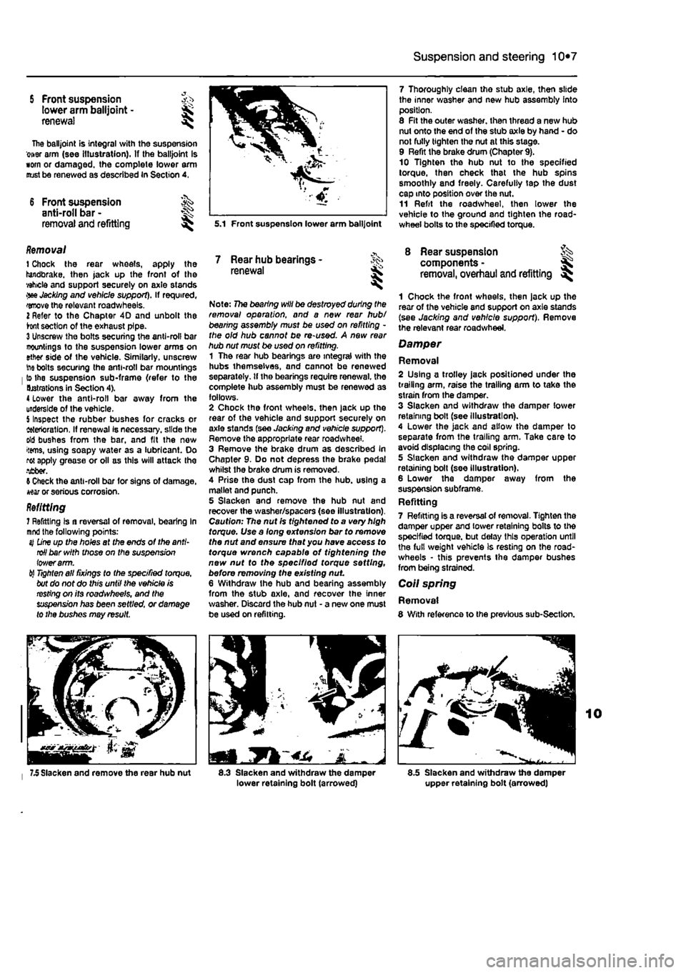
5 Front suspension >,•> tower arm balljoint -renewal ^
The balljoint is integral with the suspension ower arm (see Illustration). If the balljoint is worn or damaged, the complete lower arm oust be renewed as described In Section 4.
6 Front suspension ^ anti-roll bar -
removal and refitting s^
Removal 1 Chock the rear wheels, apply the handbrake, then jack up the front of the vehicle and support securely on axle stands •we Jacking and vehicle support). If required, wove the relevant roadwheels. 2 Refer to the Chapter 4D and unbolt the hnt section of the exhaust pipe. 3 Unscrew the bolts securing the anti-roll bar mountings to the suspension lower arms on ether side of the vehicle. Similarly, unscrew
ine
bolts securing the anti-roll bar mountings lo the suspension sub-frame (refer to the Derations in Section 4). 4 lower the anti-roll bar away from the underside of the vehicle. 5 Inspect the rubber bushes for cracks or ietertoratlon, If renewal Is necessary, slide the dd bushes from the bar, and fit the now items, using soapy water as a lubricant. Do rot apply grease or oil as this will attack the •ifiber. 9 Check the anti-roll bar for signs of damage, war or serious corrosion. Refitting 7 Refitting Is a reversal of removal, bearing In
mnd
the following points: sj
D'rw
up the holes af the ends of the anti-roll bar with those on the suspension iov/erarm. til
Tighten
all fixings to the specified torque, but do not do this until the vehicle is resting on its roadwheels, and the suspension has been settled, or damage to the bushes may result.
7.5 Slacken and remove the rear hub nut
5.1 Front suspension lower arm balljoint
7 Rear hub bearings -renewal
Note: 77ie bearing will be destroyed during the removal operation, and a new rear hub/ bearing assembly must be used on refitting -the old hub cannot be re-used. A new rear hub nut must be used on refitting. 1 The rear hub bearings are integral with the hubs themselves, and cannot be renewed separately, tf the bearings require renewal, the complete hub assembly must be renewed as follows. 2 Chock the front wheels, then jack up the rear of the vehicle and support securely on axle slands (see Jacking and vehicle support). Remove the appropriate rear roadwheel. 3 Remove the brake drum as described In Chapter 9. Do not depress the brake pedal whilst the brake drum is removed. 4 Prise the dust cap from the hub. using a mallet and punch. 5 Slacken and remove the hub nut and recover the washer/spacers (see illustration). Caution: The nut Is tightened to a very high torque. Use a long extension bar to remove the nut and ensure that you have access to torque wrench capable of tightening the new nut to the speclfiod torque setting, before removing the existing nut 6 Withdraw Ihe hub and bearing assembly from the stub axle, and recover the inner washer. Discard the hub nut - a new one must be used on refitting.
1
8.3 Slacken and withdraw the damper lower retaining bolt (arrowed)
7 Thoroughly clean tho stub axle, then slide the inner washer and new hub assembly into position. 8 Fit the outer washer, then thread a new hub nut onto the end of the stub axle by hand - do not fully tighten the nut at this stage. 9 Refit the brake drum (Chapter 9). 10 Tighten the hub nut to the specified torque, then check that the hub spins smoothly and freely. Carefully tap the dust cap into position over the nut. 11 Refit the roadwheel, then lower the vehicle to the ground and tighten the road-wheel bolts to the specified torque.
8 Rear suspension components -removal, overhaul and refitting ^
1 Chock the front wheels, then jack up the rear of the vehicle and support on axle stands (see Jacking and vehicle support). Remove the relevant rear roadwheel.
Damper
Removal 2 Using a trolley jack positioned under the trailing arm, raise the trailing arm to take the strain from the damper. 3 Slacken and withdraw the damper lower retaining boll (see Illustration). 4 Lower the jack and allow the damper to separate from the trailing arm. Take care to avoid displacing the coil spring. 5 Slacken and withdraw the damper upper retaining bolt (see illustration). 6 Lower the damper away from the suspension subframe. Refitting 7 Refitting is a reversal of removal. Tighten the damper upper and lower retaining bolts to the specified torque, but delay this operation until the full weight vehicle is resting on the road-wheels • this prevents the damper bushes from being strained.
Coil spring
Removal 8 With reference to the previous sub-Section.
8.5 Slacken and withdraw the damper upper retaining bolt (arrowed)
Page 196 of 225
Suspension and steering 10*8
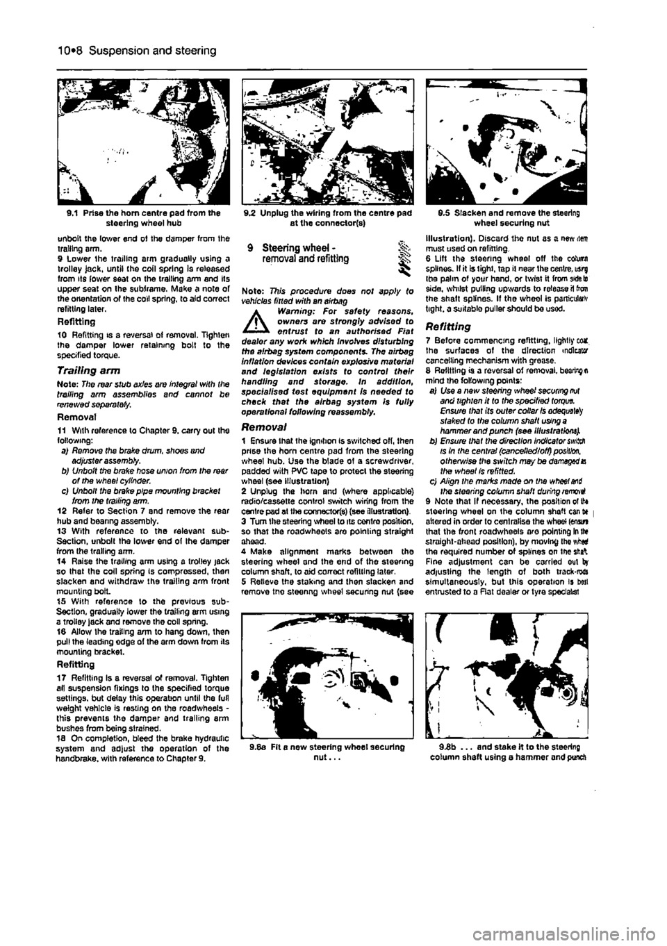
9.1 Prise the horn centre pad from the steering wheel hub unbolt the lower end of the damper from the trailing arm. 9 Lower the trailing arm gradually using a trolley jack, until the coil spring Is released from its lower seat on the trailing arm and its upper seat on the subframe. Make a note of the orientation of the coll spring, to aid correct refitting later. Refitting 10 Refitting is a reversal of removal, lighten the damper lower retaining bolt to the specified torque. Trailing arm Note: The rear stub axles are integral with the trailing arm assemblies and cannot be renewed separately. Removal 11 With reference to Chapter 9. carry out the following: a) Remove the brake drum, shoes and adjuster assembly. b) Unbolt the brake hose union from the
rear
of the wheel cylinder. c) Unbolt the brake pipe mounting bracket from the trailing arm. 12 Refer to Section 7 and remove The rear hub and beanng assembly. 13 With reference to the relevant sub-Section, unbolt the lower end of Ihe damper from the trailing arm. 14 Raise the trailing arm using a trolley jack so that the coll spring Is compressed, then slacken and withdraw the trailing arm front mounting bolL 15 With reference to the previous sub-Section, gradually lower the trailing arm using a trolley lack and remove the coll spring. 16 Allow Ihe trailing arm to hang down, then pull the leading edge of the arm down from its mounting bracket. Refitting 17 Refitting Is a reversal of removal. Tighten all suspension fixings to the specified torque settings, but delay this operation until the full weight vehicle is resting on the roadwheeis -this prevents the damper and trailing arm bushes from being strained. 18 On completion, bleed the brake hydraulic system and adjust the operation of the handbrake, with reference to Chapter 9.
9.2 Unplug the wiring from the centre pad at the connector(s)
9 Steering wheel - % removal and refitting ^
Note: This procedure does not apply to vehicles fitted with an airbag A Warning: For safety reasons, owners are strongly advisod to entrust to an authorised Fiat dealer any work which involves disturbing the airbeg system components. The airbag inflation devices contain explosive material and legislation exists to control their handling and storage. In addition, specialised test equipment Is needed to check thet the alrbag system Is fully operational following reassembly.
Removal 1 Ensure that the ignition is switched off, then prise the horn centre pad from the steering wheel hub. Use the blade of a screwdriver, padded with PVC tape to protect the steering wheel (see illustration) 2 Unplug the horn and (where applicable) radio/cassette control switch wiring from the centre pad at the connectors) (see illustration) 3 Turn the steering wheel to its centre position, so that the roadwheeis are pointing straight ahead. 4 Make alignment marks between the steering wheel and the end of the steering column shaft, to aid correct refitting later, 5 Relieve the staking and then slacken and remove tne steenng wheel securing nut (see
9.5 Slacken and remove the steering wheel securing nut Illustration). Discard the nut as a new item must used on refitting. 6 Lift the steering wheel off the column splines. If it is tight, tap il near the centre, usrg the palm of your hand, or twist it from
side to
side, whilst pulling upwards to release il ton the shaft splines. If the wheel is particular tight, a suitable puller should be used.
Refitting 7 Before commencing refitting, lightly eca. Ihe surfaces of the direction indicator cancelling mechanism with grease. 8 Refitting is a reversal of ren>oval.
bearing a
mind the following points: a) Use a new steering wheel
securing not
and tighten it to the specified
torque.
Ensure that its outer collar
Is adequate^
staked to the column shaft
using a
hammer and punch (see Illustrations). b) Ensure that the direction Indicator
swiith
is in the central (cancelled/off)
position,
otherv/ise the sivitch may be damaged X the wheel Is refitted. c) Align the marks made on the
wheel and
Ihe steering column shaft during removeI 9 Note that if necessary, the position of tf* steering wheel on the column shaft cant* | altered in order to centralise the wheel (enstn that the front roadwheeis aro pointing
In the
straight-ahead position), by moving the vMti the required number of splines on the
sfcafc
Fine adjustment can be carried out by adjusting the length of both track-rwa simultaneously, but this operation is best entrusted to a Rat dealer or tyre specialist
9.8a Fit a new steering wheet securing nut... 9.3b ... and stake it to the steering column shaft using o hammer and punch