relays FIAT PUNTO 1995 176 / 1.G Workshop Manual
[x] Cancel search | Manufacturer: FIAT, Model Year: 1995, Model line: PUNTO, Model: FIAT PUNTO 1995 176 / 1.GPages: 225, PDF Size: 18.54 MB
Page 80 of 225
2C*2 Diesel engine in-car repair procedures
Refitting 6 Locate a new gasket on the cylinder head and make sure tt Is correctly seated. 7 Lower the cover onto the gasket making sure the gasket Is not displaced, 8 Insert the mounting bolts and tighten them securely In a progressive sequence. Position Ihe support brackets as noted during removal. 9 Clip ihe coolant hoses in position then refil the air ducting.
7 Camshaft oil seal -renewal
8 Crankshaft oil seals -renswal I
9 Cylinder head -
removal
and refitting
1 Remove the timing belt and camshaft sprocket as descnbed in Sections 4 and 5. 2 Using a suitable hooked instrument, remove tho oil seal from the cylinder head taking care nol to damage the surface of the camshafl. Alternatively drill a small hole In tho oil seal and Insert a self-topping screw - the seal can then be removed by pulling on the screw with a pair of pliers. 3 Clean the seating In the cylinder head and tho end of the camshaft To prevent damage to the new oil seal as It is being fitted, wrap some adhesive tape around the end ol the camshaft and lightJy oil it. 4 Dip tho new ail s«al In oil then locate it over Ihe camshaft making sure that the sealing lips are facing inwards. 5 Using a suitable tubular drift, drive the oil seal squarely into the cylinder h*ad. Remove the adhesive tap© 6 Refit the camshaft sprocket and timing belt with reference to Sections 6 and 4.
Front (right-hand side) oil seal t The front oil seal is located in the oil pump casing on the front of the crankshaft. Remove the timing belt as described in Section 4 and the crankshaft sprocket as described in Section 5, 2 Using a suitable hooked instrument, remove the oil seal from the oil pump casing taking care not to damage the surface of the crankshaft. Alternatively drill a small hole In the oil soal and insert a self-tapping screw - the seal can then be removed by pulling on the screw with a pair of pliers. 3 Clean the seating in the oH pump and the surface of the crankshaft. To prevent damage to the new off seal as It Is being fitted, wrap some adhesive tape around the end of tha crankshaft and lightly oil it. 4 Oip the new oii seal In oil then otter it up to the oil pump casing making sure that the sealing Hps are facing inwards,
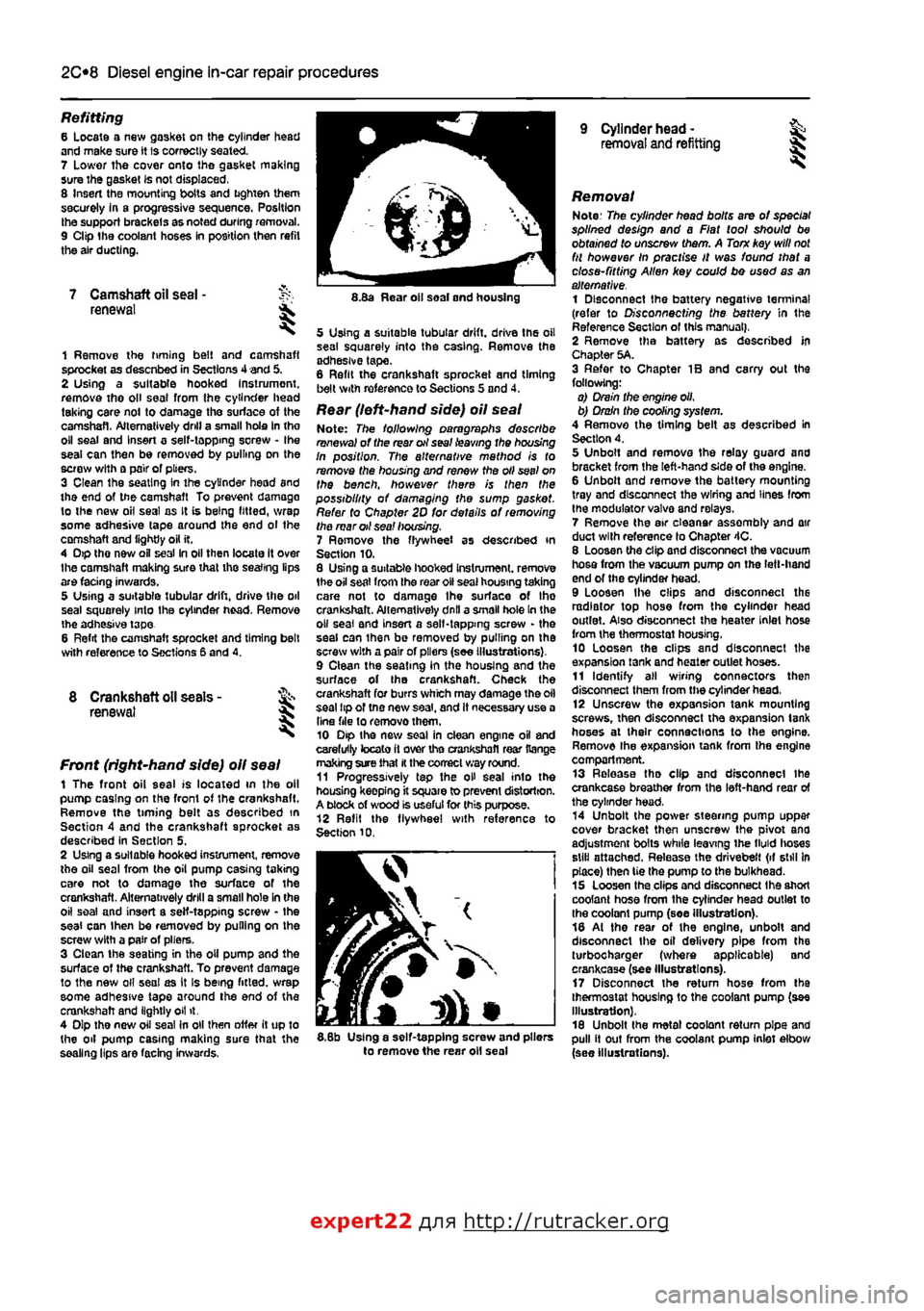
8.Ba Rear oil soal and housing
5 Using a suitable tubular drift, driva the oil sea! squarely into the casing. Remove the adhesive tape. 6 Refit the crankshaft sprocket and timing belt with reference to Sections 5 and 4.
Rear (left-hand side) oil seal Note: The following paragraphs describe renewal of the rear oil seal leaving the housing In position. The alternative mathod is to remove the housing and renew the oil seel on the bench, however there is then the possibility of damaging the sump gasket. Refer to Chapter 2D for details of removing the mar oil sea! housing. 7 Ramove the flywheel as described in Section 10. 8 Using a suitable hooked Instrument. remove 1he oil seat from the roar oil seal housing taking care not to damage Ihe surface of Ihe crankshaft. Alternatively dnll a small hole In the o» seal and insert a self-tapping screw - the seal can ihan be removed by pulling on the screw with a pair of pliers (see Illustrations), 9 Clean the seating in the housing and the surface of the crankshaft. Check the crankshaft for burrs which may damage the oil seal tip of tno new saal, and It necessary use a Una file to removothem. 10 Dip the new soal in clean engine oil and carefully tocato it over tho crankshafl rear Range making sure that
H
the correct way round. 11 Progressively tap the oH seal into the housing keepfng it square to prevent distortion. A block of wood is useful for this purpose. 12 Refit the flywheel with reference to Section 10.
I
5.8b Using a self-tapping screw and pliers to remove the rear oil seal
Removal Note: The cylinder head bolts are of special splined design and a Fiat tool should be obtained to unscrew them. A Torn key will
not
fit however In practise It was found that a close-fitting Allen key could bo used as an alternative. 1 Disconnect the battery negative terminal (refer to Disconnecting the battery in the Reference Section of this manual), 2 Remove tha battery as described In Chapter 5A. 3 Refer to Chapter IB and carry out the following: o) Drain the engine oil, b) Drain the cooling system. 4 Remove the timing belt as described in Section 4. 5 Unbolt and remova the relay guard and bracket from the left-hand side of the engine. 6 Unbolt and remove the battery mounting tray and disconnect the wiring and lines from the modulator valva and relays. 7 Remove the air eleanar assembly and air duct with reference lo Chapter 4C. 8 Loosen the clip and disconnect the vacuum hosa from the vacuum pump on the left-hand end of the cylinder head. 9 Loosen Ihe clips and disconnect the radiator top hose from the cylinder head outlet. Also disconnect the heater inlet hose from the thermostat housing, 10 Loosen the clips and disconnect the expansion tank and heater outlet hoses. 11 Identify all wiring connectors then disconnect them from the cylinder head, 12 Unscrew the expansion tank mounting screws, then disconnect tha expansion tank hoses at their connections to the engine. Remove the expansion tank from tha engine compartment. 13 Release tha clip and disconnect ihe crankcase breather from the left-hand rear of the cylinder head. 14 Unbolt the power steering pump uppar cover bracket then unscrew the pivot ana adjustment bolts while leaving ihe tMd lioses still attached. Release the drivebelt (if still In place) then tie the pump to the bulkhead. 15 Loosen tha clips and disconnect Ihe short coolant hose from the cylinder head outlet to the coolant pump (soe illustration). 18 At the rear of the engine, unbolt and disconnect the oil delivery pipe from the turbocharger (where applicable) and crankcase (see Illustrations). 17 Disconnect the return hose from tha thermostat housing to the coolant pump (see Illustration), 18 Unbolt the metal coolant return pipe and pull it out from the coolant pump inlet elbow (see Illustrations).
expert22 flna http://rutracker.org
Page 125 of 225
Ihe right-hand front roadwheel and the protective plastic cover under the wheelarch. 37 Disconnect the sensor wiring plug on the front of the engine. 38 Detach the sensor from its mounting. Refitting 39 After refitting Ihe sensor use a feeler blade to check that the gap between sensor and the serrated part of the crankshaft pulley Is between 0.5 and 1.S mm. No adjustment is possible and if the gap is incorrect the sensor and pulley should be checked for possible damage.
Electronic control unit (ECU)
Removal Note: 77ie engine management system has a (earning capability which allows the ECU to store details of the engine's running
characteristics
in its memory,
This
memory
will
tie erased by the disconnection of the battery
cables,
with the resuit that the engine may idle
roughly,
or lack performance for a while, until
the
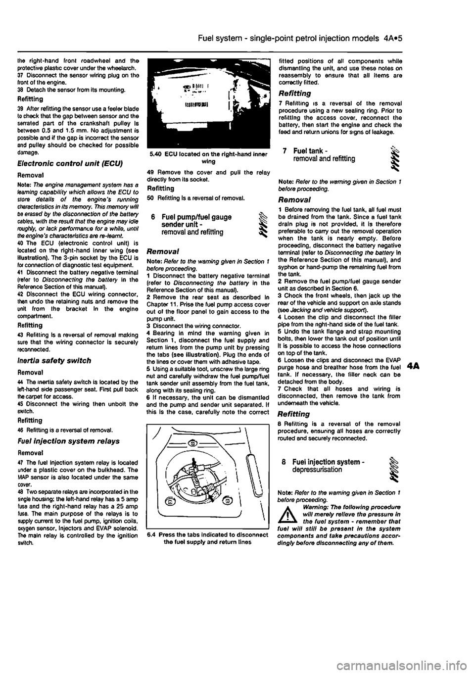
engine's characteristics are re-teamt. 40 The ECU {electronic control unit) is located on the right-hand Inner wing (see illustration). The 3-pin socket by the ECU is for connection of diagnostic test equipment. 41 Disconnect the battery negative terminal (refer to D/sconnecffng the battery in the Reference Section of this manual). 42 Disconnect the ECU wiring connector, then undo the retaining nuts and remove the unit from the bracket In the engine compartment. Refitting 43 Refitting Is a reversal of removal making sure that the wiring connector is securely reconnected. Inertia safety switch
Removal 44 The inertia safety switch is located by the left-hand side passenger seat. First pull back
the
carpet for access. 45 Disconnect the wiring then unbolt the switch. Refitting 48 Refitting is a reversal of removal.
Fuel injection system relays
Removal 47 The fuel injection system relay is located under a plastic cover on the bulkhead. The MAP sensor is also located under the same cover. 48 Two separate relays are incorporated in the single housing; the left-hand relay has a 5 amp fuse and the right-hand relay has a 25 amp fuse. The main purpose of the relays is to supply current to the fuel pump, ignition coils, oxygen sensor. Injectors and EVAP solenoid. The main relay is controlled by the ignition switch.
4A*2 Fuel system - single-point petrol Injection models
6 Fuel pump/fuel gauge sender unit -removal and refitting
Removal Note: Refer to the warning given in Section 1 before proceeding. 1 Disconnect the battery negative terminal (refer to Disconnecting the battery in the Reference Section of this manual). 2 Remove the rear seat as described in Chapter 11. Prise the fuel pump access cover out of the floor panel to gain access to the pump unit. 3 Disconnect the wiring connector. 4 Bearing in mind the warning given in Section t, disconnect the fuel supply and return lines from the pump unit by pressing the tabs (see illustration). Plug the ends of the lines or cover them with adhesive tape. 5 Using a suitable toot, unscrew the large ring nut and carefully withdraw the fuel pump/fuel tank sender unit assembly from the fuel tank, along with its sealing ring. 6 If necessary, the unit can be dismantled and the pump and sender unit separated. If this is the case, carefully note the correct
fitted positions of oil components while dismantling the unit, and use these notes on reassembly to ensure that all items are correctly fitted.
Refitting 7 Refitting is a reversal of the removal procedure using a new sealing ring. Prior to refitting the access cover, reconnect the battery, then start the engine and check the feed and return unions for signs of leakage.
5.40 ECU located on the right-hand inner wing 49 Remove the cover and pull the relay directly from its socket. Refitting 50 Refitting Is a reversal of removal.
7 Fuel tank -removal and refitting
6.4 Press the tabs Indicated to disconnect the fuel supply and return tines
Note: Refer to the warning given in Section 1 before proceeding.
Removal 1 Before removing the fuel tank, all fuel must be drained from the tank. Since a fuel tank drain plug is not provided, it is therefore preferable to carry out the removal operation when the tank is nearly empty. Before proceeding, disconnect the battery negative terminal (refer to Disconnecting the battery In the Reference Section of this manual), and syphon or hand-pump the remaining fuel from the tank. 2 Remove the fuel pump/fuel gauge sender unit as described in Section 6. 3 Chock the front wheels, then jack up the rear of the vehicle and support on axle stands (see Jacking and vehicle support). 4 Loosen the clip and disconnect the filler pipe from the nght-hand side of the fuel tank. 5 Undo the tank flange and strap mounting bolts, then lower the tank out of position until It is possible to access the hose connections on top of the tank. 6 Loosen the clips and disconnect the EVAP purge hose and breather hose from the fuel tank. If necessary, the filler neck can be detached from the body. 7 Check that all hoses and wiring is disconnected, then remove the tank from underneath the vehicle. Refitting 8 Refitting is a reversal of the removal procedure, ensuring all hoses are correctly routed and securely reconnected.
8 Fuel injection system - ^ depressurisation
Note: Refer to the warning given In Section t before proceeding.
A
Warning; The following procedure will merely relievo the pressure in the fuel system • remember that fuel will still be present In the system components and take precautions accor-dingly before disconnecting any of them.
Page 132 of 225
4A*2 Fuel system -
single-point
petrol Injection models
b) Ensure that the injector retaining clips are securely seated c) Make sure the fuel supply and return hoses are correctly fitted as noted on removal, d) Check that all vacuum and electrical connections are remade
correcily
and securely. e) On completion check the fuel rail and injectors for fuel leaks.
Fuel pressure regulator Note: On J998 models onward, the fuel pressure regulator is an integral pad of the fuel pump and cannot be renewed separately. The following procedure applies to pre-1998 models only. Removal 17 Remove the air cleaner and inlet air ducts as described In Section 2. 18 Oepressurise the fuel system as described in Section 9. 19 Disconnect the vacuum hose from the port on the side of the regulator. 20 Extract the retaining clip and pull the pressure regulator out of Ihe fuel rail. 21 Remove the O-ring seal. Refitting 22 Refit the fuel pressure regulator by following Ihe removal procedure in reverse, noting the following points: a) Renew the O'ting seal and smear it with a little Vaseline before assembling. b) When fitting the retaining clip, use a suitable socket or metal tube (o press In the three anchorage points at Ihe same time. c) Refit the vacuum hose securely.
Idle control stepper motor
23 Refer to Chapter 4A.
Throttle potentiometer 24 Refer to Chapter 4A,
Intake air temperature sensor 25 Refer to Chapter 4A.
Manifold absolute pressure (MAP) sensor 26 Reler to Chapter 4A.
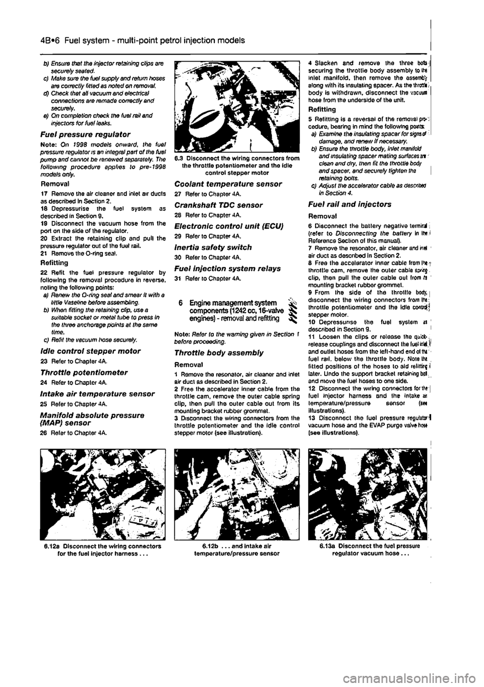
6.12a Disconnect the wiring connectors for the fuel injector harness ...
6.3 Disconnect the wiring connectors from the throttle potentiometer and the idle control stepper motor
Coolant temperature sensor 27 Refer to Chapter 4A. Crankshaft TDC sensor 28 Refer to Chapter 4A. Electronic control unit (ECU)
29 Refer to Chopter 4A.
Inertia safety switch 30 Refer to Chapter 4A. Fuel injection system relays 31 Refer to Chapter 4A.
6 Engine management system ^ components
(1242
cc,16-vatve S engines) - removal and refitting ^
Note: Refer to the warning given in Section t before proceeding.
Throttle body assembly
Removal 1 Remove the resonator, air cleaner and inlet air duct as described in Section 2. 2 Free Ihe accelerator inner cab
4 Slacken and remove the three bob j securing the throttle body assembly to ite inlet manifold. Ihen remove the assent?/ along with its insulating spacer. As the
throaii 1-
body is withdrawn, disconnect the vacuum hose from the underside of the unit. Refitting 5 Refitting is a reversal of the removal pi>: cedure, bearing in mind the following pants a) Examine the insulating spacer for signs d damage, and renew if necessary. b) Ensure the throttle body, inlet
manddd
and insulating spacer mating surfaces at -clean and dry. then fit the throttle
btxty
and spacer, and securely tighten the retaining bolts. c) Adjust Ute accelerator cable as desciter /nSecfw?4.
Fuel rail and injectors
Removal 6 Disconnect the battery negative termrul; (refer to Disconnecting the battery in ir*J Reference Section ol this manual), 7 Remove the resonator, air cleaner arid io«l 1 air duct as descnbed in Section 2. 8 Free the accelerator Inner cablc from l>*
1
throttle cam, remove the outer cable sprig. clip, then pull the outer cable out from
>H
mounting bracket rubber grommet, 9 From the side of the throttle bod/, | disconnect the wiring connectors from Ihs: throttle potentiometer and the idle cofttro^ stepper motor. 10 Oepressunse the fuel system si ' described in Section 9. ' 11 Loosen the clips or release tho quick-. release couplings and disconnect the fuel MdJ' and outlet hoses from the left-hand end oftfu fuel rail, below the throttle body. Note IM fitted positions ol the hoses to aid relirtirf i later. Undo the support bracket retaining bol and move the fuel hoses to one side. 12 Disconnect Ihe wiring connectors forth* fuel injector harness and the Intake an temperature/pressure sensor (m illustrations). 13 Disconnect the fuel pressure regulator-! vacuum hose and the EVAP purgo vaive h«* (see illustrations).
6.13a Disconnect the fuel pressure regulator vacuum hose...
Page 134 of 225
4A*2 Fuel system -
single-point
petrol Injection models
Refitting 37 Refitting Is a reversal of removal making sure that the wiring connector is securely reconnected.
Inertia safety switch 36 Refer to Chapter 4A, Fuel injection system relays Removal 39 The fuel injection system twin relay Is located under a plastic cover on the engine compartment bulkhead. 40 The main purpose of the relay Is to supply current to the fuel pump, ignition coils, oxygen sensor, Injectors and EVAP solenoid. The relay is controlled by the ignition switch. A15 amp fuse, protecting ihe fuel pump, oxygen sensor and EVAP solenoid is located adjacent to the relay. 41 Remove the cover and pull the relay directfy from Its socket. Refitting 42 Refitting is a reversal of removal.
7 Fuel pump and fuel gauge sender unit - JK removal
and
refitting ^
Removal Note: Refer fo (he warning given in Section 1 before proceeding. 1 Disconnect the battery negative terminal (refer to Disconnecting the battery In the Reference Section of this manual). 2 Depreasurise the fuel system as described in Section 9. 3 Remove the rear soat as described In Chapter 11. Prise the fuel pump access cover out of the floor panel to gain access to the pump unit. On later models, undo the three retaining screws to release the cover. 4 Disconnect the wiring connector. 5 Bearing In mind the warning given In Section t, disconnect Ihe fuel supply and, where applicable, the return lines from tho pump unit by pressing the tabs. Plug the ends of the lines or cover them with adhesive tape. 6 Using a suitable tool, unscrew the large ring nut and carefully withdraw the fuel pump/fuel tank sender unit assembly from the fuel tank, along with its sealing rtng. 7 If necessary, the unit can be dismantled and the pump and sender unit separated. If this is (he case, carefully note the correct fitted positions of all components while dismantling the unit, and use these notes on reassembly to ensure that all items are correctly fitted.
Refitting 8 Refitting is a reversal of the removal procedure using a new sealing ring. Prior to refitting the access cover, reconnect the battery, then start the engine and check the fuel line unlon(s) (or signs of i
Fuel
tank -removal and refitting
Refer to Chapter 4A.
9 Fuel injection system -depressurisatton
Note: Refer to the warning given In Section 1 before proceeding.
A
Warning: The following procedure will merely relieve the pressure In the fuel system • remember that fuel will still be present In the system components and take precautions accord-ingly before disconnecting any of them. 1 The fuel system referred to in this Section is defined as the lank-mounted fuel pump, tha fuel filter, the fuel rail, the fuel injectors, and the metal pipes and flexible hoses of the fuel lines between these components. All these contain fuel which will be under pressure while the engine Is running and/or while the Ignition is switched on. The pressure will remain for some time after the Ignition has been switched off. and must be relieved before any of these components are disturbed for servicing work. 2 Disconnect the battery negative terminal (refer to Disconnecting the battery In the Reference Section of this manual). 3 Have a large rag ready to cover the union to be disconnected and, if possible, place a con-tainer beneath the relevant connection/union. 4 Slowly loosen the connection or union nut (as applicable) to avoid a sudden release of pressure, and ensure that the rag is wrapped around the connection to catch any fuef spray which may be expelled. Once the pressure is released, disconnect the fuel line, and Insert plugs to minimise fuel loss and prevent the entry of dirt Into the fuel system. Note that on later models, quick-release fuel couplings are used on many of the fuel line connections. To release these couplings, depress the two clips on the side of the coupling while keeping the fuel line pushed In. With the clips depressed, slowly withdraw the fuel line from the coupling allowing the fuel pressure to release, then withdraw the fuel line fully.
10 Inlet manifold-removal
and
refitting
Note: Refer fo the warning given in Section 1 before proceeding.
1242 cc (8-valve) engines
Removal 1 Remove ihe throttle body assembly as described in Section 5.
2 Remove the fuel rail and injectors at described in Section 5. 3 Drain the cooling system ss described n Chapter 1A. 4 Disconnect the wiring connector from ih* coolant temperature sensor (situated on it* left-hand side of the manifold). 5 Undo the bolt securing the accelerator cable mounting bracket to the manifold, am position it clear of the manifold. 6 Slacken the retaining clip and disconnect the coolant hose from the rear of the mandold 7 Disconnect the brake vacuum hose, 6 Undo the seven manifold retaining nuisw bolts, and remove the manifold from tta engine. Remove the gasket and discard tti new one should be used on refitting. Refitting
9 Refitting is a reverse of the removjf procedure, noting the following points: a) Ensure that the manifold and cylinder lim mating surfaces are dean and
dry.
and fill new manifold gasket. Refit the
manifold
and securely tighten Its retaining
nuts.
b) Ensure all relevant hoses are recorwscfed fo their original positions and are
sacurtfy
held (Where necessary; by the
retaining
clips. c) Refit the fuel rail and injectors, and
the
throttle body assembly with
reference to
Sect/on 5. d) On completion, refill the cooling
system
as described in Chapter 1A. 1242 cc (16-valve) engines
Removal 10 Disconnect the battery negative ternnncf (refer to Disconnecting the battery in ths Reference Section of this manual). 11 Remove the resonator, air cleaner and inlet air duct as described In Section 2. 12 Drain the cooling system as described r, Chapter 1A. 13 Free the accelerator inner cable from IN throttle cam. remove the outer cable spring dip. then pull the outer cable out from itt mounting bracket rubber grommet. 14 From the side of the throttle boOf, disconnect the wiring connectors from the throttle potentiometer and the Idle contrd stepper motor. Disconnect the coolant temperature sensor wiring connector located in the Inlet manilold below the throttie bodr, and disconnect the brake servo vacuum hose. 15 Disconnect Ihe wiring connectors for the fuel in|ector harness and the Intake a* temperature/pressure sensor, thtn disconnect the fuel pressure regulator vacuum hose and the EVAP purge valve
hose
(see illustration). 16 Undo Ihe two bolts securing the plastic Inlet manifold upper section to the lower section. Release the spark plug HT lead from the location groove in the manifold upper section, then lift Ihe upper section, complete with throttle body, off the engine. Recover
the
O-rings from the manifold pons.
Page 144 of 225
4D«1
Chapter 4 Part D:
Exhaust and emission control systems
Contents
Catalytic converter - general Information and precautions 7 Crankcase emission system • general information 3 Evaporative loss emission control system • information and component renewal 2
Degrees of difficulty
Exhaust manifold - removal and refitting 5 Exhaust system - general information and component renewal .... 6 General information 1 Lambda oxygen sensor - removal and refitting 4
Easy, suitable
tor novice with fittie ^
1 experience
Fairly easy, suitable for beginner with ^ some experience ^
Fairiy dfficult, lb suitable for competent ^ DIY mechanic ^
Difficult, suitable for experienced DIY ^ mechanic
Very difficult, ^ suitable far expert DIY or professional
Specifications
Torque wrench settings Exhaust down pipe to manifold Exhaust manifold Exhaust system mounting Exhaust to catalytic converter: M8 M10x1.25
Nm Ibfft 24 18 24 18 27 20
24 18 40 30 53 39
1 General information
Emission control systems All petrol engine models use unleaded petrol and are controlled by engine management systems that are 'tuned' to give the best compromise between driveability. luel consumption and exhaust emission production. In addition, a number of systems are fitted that help to minimise other harmful emissions: a crankcase emission-control system (petrol models only) that reduces the release of pollutants from the crankcase, an evaporative loss emission control system (petrol models only) to reduce the release of hydrocarbons from the fuel tank, a catalytic converter (petrol and diesel models) to reduce exhaust gas pollutants, and an Exhaust Gas Recirculation (EGR) system (turbo diesel models only) to reduce exhaust emissions. Crankcase emission control To reduce the emission of unburned hydrocarbons from the crankcase Into the atmosphere, the engine is sealed and the blow-by gases and oil vapour are drawn from inside the crankcase, through a flame trap.
into the inlet tract to be burned by the engine during normal combustion. Under conditions of high manifold depression (idling, deceleration) the gases will by sucked positively out of the crankcase. Under conditions of low manifold depression (acceleration, full-throttle running) ihe gases are forced out of the crankcase by the (relatively) higher crankcase pressure: if the engine is worn, the raised crankcase pressure (due to increased blow-by) will cause some of the flow to return under all manifold conditions. Exhaust emission control -petrol models To minimise the amount of pollutants which escape Into the atmosphere, a catalytic converter is fitted In the exhaust system. The fuel system is of the closed-loop type, in which a Lambda (or oxygen) sensor In the exhaust system provides the engine management system ECU with constant feedback, enabling the ECU to adjust the air/fuel mixture to optimise combustion. The Lambda sensor has a heating element built-in that Is controlled by the ECU through the Lambda sensor relay to quickly bring the sensor's tip to Its optimum operating temperature. The sensor's tip Is sensitive to oxygen and relays a voltage signal to the ECU
that varies according on the amount of oxygen In the exhaust gas. If the inlet air/fuel mixture is too rich, the exhaust gases are low in oxygen so the sensor sends a low-voltage signal, the voltage rising as the mixture weakens and the amount of oxygen rises In the exhaust gases. Peak conversion efficiency of all major pollutants occurs if the inlet air/fuel mixture Is maintained at the chemlcally-con*ect ratio for the complete combustion of petrol of 14.7 parts (by weight) of air to
1
part of fuel (the stoichiometric ratio). The sensor output voltage alters in a large step at this point, the ECU using the signal change as a reference point and correcting the Inlet air/fuel mixture accordingly by altering the fuel Injector pulse width. Exhaust emission control -diesel models An oxidation catalyst is fitted in the exhaust system of all diesel engine models. This has the effect of removing a large proportion of the gaseous hydrocarbons, carbon monoxide and particulates present in the exhaust gas. An Exhaust Gas Recirculation (EGR) system Is fitted to all turbo diesel engine models. This reduces the level of nitrogen oxides produced during combustion by Introducing a proportion of the exhaust gas back into the inlet manifold, under certain engine operating
Page 214 of 225
10*1
Chapter 12
Body electrical systems
Contents
Bulbs (exterior lights) - renewal 4 Bulbs (interior lights) - renewal 5 Electrical fault finding - general information 2 Exterior light units - removal and refitting 6 Fuses and relays - general Information 3 General information and precautions 1 Headlight beam alignment • general Information 6 Horn • removal and refitting 9 Instrument panel - removal and refitting 7 Loudspeakers - removal and refitting 10
Degrees of difficulty
Radio aerial - removal and refitting 11 Radio/cassette player • removal and refitting 12 Speedometer drive cable - removal and refitting 13 Switches - removal end refitting 14 Tailgate wiper motor - removal and refitting 15 Windscreen wiper motor - removal and refitting 17 Windscreen/tailgate washer system components • removal and refitting 16 Wiper arm • removal and refitting 18
Easy,
statable for ^
novice with liffle
|| experience ^
Fairly
easy,
suitable for beginner with ^ some experience ^
Fabtycffficiit,
suitable
for competent ^
DIY
mechanic ^
Difficult, suitable for
^ experienced DIY JR mechanic
Very difficult,
A,
suitable
for
expert DIY
Sj or professional ^
Specifications
Bulb ratings Watts Headlights 60/55 Front long range driving light 55 Front fogllght 55 Front direction Indicator light 21 Front sidelight 5 Front direction indicator repeater light 5 Stop light 21 Tall light 5 Rear direction indicator light 21 Reversing light 21 near fogllght 21 Hear number plate light 5 Courtesy light 10 Map reading light 5
1 Genera! information and precautions
A
Warning: fie/Ore carrying out any work on the electrical system, read through the precautions given in Safety first! at the beginning of this manual, and in Chapter 8. The electrical system is of 12-volt negative earth type. Power for the lights and all electrical accessories is supplied by a lead/acid type battery, which is charged by the alternator. This Chapter covers repair and service procedures for the various electrical components not associated with the engine. Information on the battery, alternator and starter motor can be found in Chapter 5. It should be noted that, prior to working on any component In the electrical system, the
battery negative terminal should first be disconnected, to prevent the possibility of electrical short-circuits and/or fires. Caution: Before proceeding, refer to Disconnecting the battery In the Reference Section of this manual for further information.
2 Electrical fault finding-general information
Note: Refer to the precautions given In Safety first! and in Section 1 of this Chapter before starting work. The following tests relate to testing ot the main electrical circuits, and should not be used to test delicate electronic circuits (such as antHock braking systems), particularly where an electronic con fro/ module is used.
General 1 A typical electrical circuit consists of an electrical component, any switches, relays, motors, fuses, fusible links or circuit breakers related to that component, and the wiring and connectors which link the component to both the battery and the chassis. To help to pinpoint a problem in an electrical circuit, wiring diagrams are Included at the end of this manual. 2 Before attempting to diagnose an electrical fault, first study the appropriate wiring diagram, to obtain a more complete understanding of the components included In the particular circuit concerned. The possible sources of a fault can be narrowed down by noting whether other components related to the circuit are operating properly. If several components or circuits fait at one time, the problem Is likely to be related to a shared fuse or earth connection.
Page 215 of 225
12*2 Body electrical systems
3 Electrical problems usually stem from simple causes, such as loose or corroded connections, a faulty earth connection, a blown fuse, a melted lusible link, or a fautty relay {refer to Section 3 for details of testing relays). Visually inspect the condition of all (uses, wires and connections in a problem circuit before testing the components. Use the wiring diagrams lo determine which terminal connections will need to be checked, in order to pinpoint the trouble-spot. 4 The basic tools required for electrical fault-finding include a circuit tester or voltmeter (a 12-volt bulb with a set of lest leads can also be used for certain tests}; a self-powered test light (sometimes known as a continuity tester); an ohmmeter (to measure resistance): a battery and set of tesi leads: and a lumper wire, preferably with u circuit breaker or fuse incorporated, which can be used to bypass susoect wires or electrical components. Before attempting to locate a problem with tost instruments, use the wiring diagram to determine where to make the connections. 5 To find the source of an intermittent wiring fault (usually due to a poor or dirty connection, or damaged wiring Insulation), a wiggle test can be performed on the wiring. This involves wiggling the wiring by hand, to see if tha fault occurs as the wiring Is moved. It should be possible to narrow down the source of the fault to a particular section of wiring. This method of testing can be used in conjunction with any of the tests descnbed in the following sub-Sections. 6 Apart from problems due to poor connections, two basic types of fault can occur in an electrical circuit - open-circuit, or short-circuit. 7 Open-circuit faults are caused by a break somewhere in the circuit, which prevents current from flowing. An open-circuit fault will prevent a component from working, but will not cause the relevant circuit fuse to blow 8 Short-circuit faults are caused by a shod somewhere in the circuit, which allows Die current flowing In the circuit to escape along an alternative route, usually to earth. Short-circuit faults are normally caused by a breakdown in wiring insulation, which allows a feed wire to touch either another wire, or an earthed component such as the bodysheli. A short-circuit fault will normally cause the relevant circuit fuse to blow.
Finding an open-circuit 9 To check for an opon-circuit, connect one lead of a circuit tester or voltmoter to either the negative battery terminal or a known good earth. 10 Connect the other lead to a connector in the circuit being tested, preferably nearest to the batter/ or luse. 11 Switch on the circuit, bearing In mind that some circuits are live only when tho ignition switch is moved to a particular position. 12 If voltage is present (Indicated either by
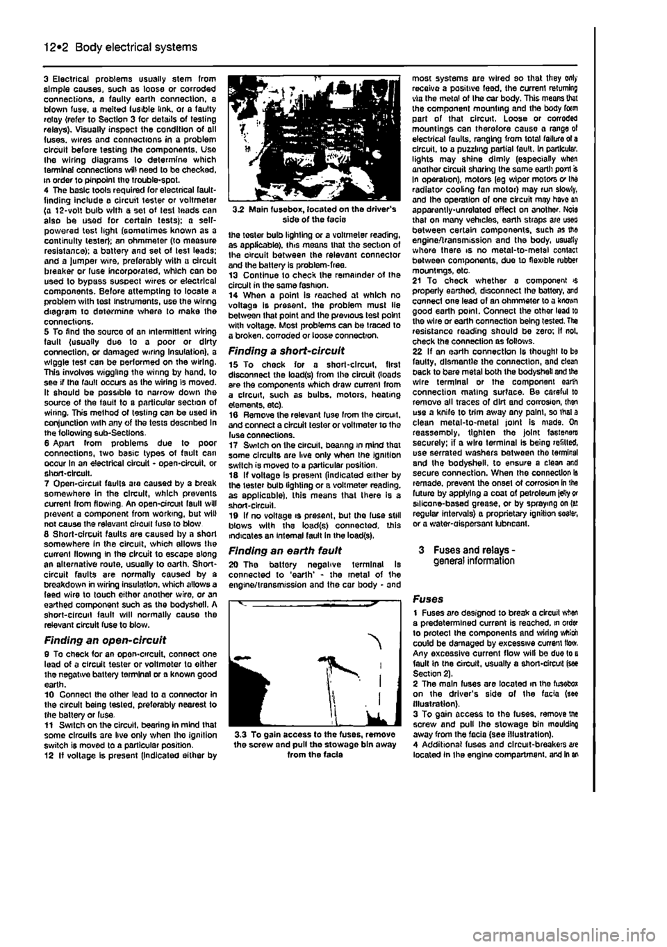
3.2 Main fuse box, located on the driver's side of the facie the toster bulb lighting or a voltmeter reading, as applicable), this means that tho section of Ihe circuit between the relevant connector and the battery is problem-free. 13 Continue to check the remainder ot the circuit in the same fashion. 14 When a point is reached at which no voltage Is present, the problem must lie between that point and the previous test point with voltage. Most problems can be traced to a broken, corroded or loose connection.
Finding a short-circuit 15 To check for a short-circuit, first disconnect the load(s) from the circuit (loads are the components which draw current from a circuit, such as bulbs, motors, heating elements, etc). 16 Remove the relevant luse Irom the circuit, and connect a circuit tester or voltmeter to the luse connections. 17 Switch on the circuit, beanng in mind that some circuits are live only when the ignition switch is moved to a particular position. 18 If voltage is present (indicated either by the tester bulb lighting or a voltmeter reading, as applicable), this means that there Is a short-circuit. 19 If no voltage is present, but the fuse still blows with the load(s) connected, this indicates an internal fault in the load(s).
Finding an earth fault 20 The battery negative terminal Is connected to 'earth' - the metal of the engine/transmission and the car body - and
I
IK
J 3.3 To gain access to the fuses, remove the screw and pull the stowage bin away from the facia
most systems are wired so that they only receive a positive feed, the current returning via the metal of Ihe car body. This means that the component mounting and the body form part of that circuit. Loose or corroded mountings can therefore cause a range of electrical faults, ranging from total failure ot a circuit, to a puzzling partial fault. In particular, lights may shine dimly (especially when another circuit sharing the same earth port In operation), motors (eg wiper motors v Ihe radiator cooling fan motor) may run slowly, and Ihe operation of one circuit may have an apparently-unrelated effect on another. Ncie that on many vehicles, earth straps axe uses between certain components, such as the engine/transmission and the body, usually whore there is no metal-to-metal contact between components, due to flexible rubber mountings, etc. 21 To check whether a component $ properly earthed, disconnect Ihe battery, and connect one lead of an ohmmeter to a kwwi good earth point. Connect the other lead to the wire or earth connection being tested. Tha resistance reading should be zero; if not. check the connection as follows. 22 If an earth connection Is thought to be faulty, dismantle the connection, and clean pack to bare metal both the bodysheli and ite wire terminal or the component earth connection mating surface. Be careful to remove all traces of dirt and corrosion, then use a knife to trim away any palm, so thai a clean metal-to-metal joint Is mads. On reassemoly, tighten the joint fasteners securely: if a wire terminal Is being refitted, use serrated washers between tho terminal and the bodysheli. to ensure a clean and secure connection. When the connection is remade, prevent the onset ot corrosion in the future by applying a coat of petroleum idly
or
stlicone-based grease, or by spraying on (a: regular intervals} a proprietary ignition eoater, or a water-aispersant lubneant.
3 Fuses and relays -general information
Fuses 1 Fuses are designod to break a circuit when a predetermined current is reached, in order to protect the components and wiring wttioh could be damaged by excessive current How. Any excessive current flow will be due to a fault in the circuit, usually a short-circuit (see Section 2). 2 The main fuses are located in the fusefcox on the driver's side of the facia (see illustration). 3 To gain access to the fuses, remove tne screw and pull the stowage bin moulding away from the facia (see illustration). 4 Additional fuses and circuit-breakers are located In the engine compartment, and in an
Page 216 of 225
Body electrical systems 12*3
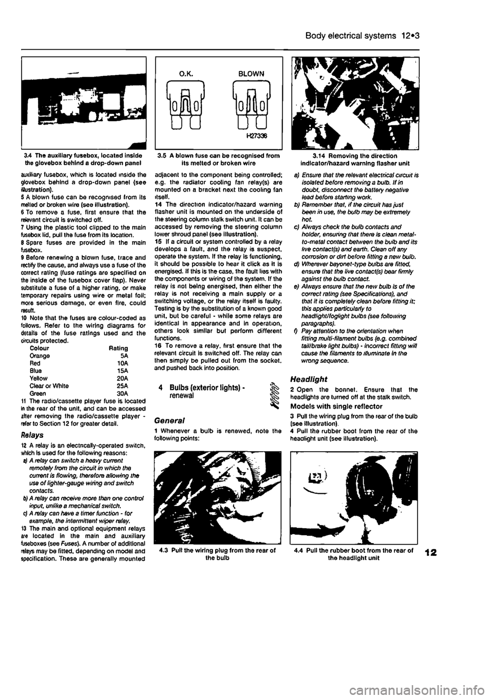
3.4 The auxiliary fusebox, located inside the glovebox behind a drop-down panel auxiliary fusebox, which is located inside the glovebox behind a drop-down panel (see Illustration). 5 A blown fuse can be recognised from its melted or broken wire (see illustration). 6 To remove a fuse, first ensure that the relevant circuit is switched off. 7 Using the plastic tool clipped to the main fusebox lid, pull the fuse from its location. 8 Spare fuses are provided in the main fusebox. 9 Before renewing a blown fuse, trace and rectify the cause, and always use a fuse of the correct rating (fuse ratings are specified on the inside of the fusebox cover flap). Never substitute a fuse of a higher rating, or make temporary repairs using wire or metal foil; more serious damage, or even fire, could result. 10 Note that the fuses are colour-coded as follows. Refer to the wiring diagrams for details of the fuse ratings used and the circuits protected. Colour Rating Orange 5A Red 10A Blue 15A Yellow 20A Clear or White 25A Green 30A 11 The radio/cassette player fuse is located In the rear of the unit, and can be accessed after removing the radio/cassette player -refer to Section 12for greater detail.
Relays 12 A relay is an electncally-operated switch, which Is used for the following reasons: 4 A relay can switch a heavy current remotely from the circuit in which the current is flowing, therefore allowing the use of lighter-gauge wiring and switch contacts.
b)
A relay can receive more than one control input, unlike a mechanical switch. c) A relay can have a timer function - for example, the intermittent wiper relay. 13 The main and optional equipment relays are located in the main and auxiliary toseboxes (see Fuses). A number of additional relays may be fitted, depending on model and specification. These are generally mounted
3.5 A blown fuse can be recognised from its melted or broken wire adjacent lo the component being controlled; e.g. the radiator cooling fan relay(s) are mounted on a bracket next the cooling fan itself. 14 The direction Indicator/hazard warning flasher unit is mounted on the underside of the steering column slalk switch unit. It can be accessed by removing the steering column lower shroud panel (see illustration). 15 If a circuit or system controlled by a relay develops a fault, and the relay is suspect, operate the system. If the relay is functioning, it should be possible to hear it click as it is energised, if this is Ihe case, the fault lies with the components or wiring of the system. If the relay is not being energised, then either the relay is not receiving a main supply or a switching voltage, or the relay itself is faulty. Testing is by the substitution of a known good unit, but be careful - while some relays are identical in appearance and in operation, others look similar but perform different functions. 16 To remove a relay, first ensure that the relevant circuit is switched off. The relay can then simply be pulled out from the socket, and pushed back into position.
4 Buibs (exterior lights) -renewal
General 1 Whenever a bulb is renewed, note the following points:
3.14 Removing the direction indlcator/ha2ard warning flasher unit
a) Ensure that the relevant electrical circuit is isolated before removing a bulb. If in doubt, disconnect the battery negative lead before starting work. b) Remember that, if the circuit has just been in use, the bulb may be extremely hot. c) A/ways check the bulb contacts and holder, ensuring that there is clean metal-to-metal contact between the bulb and its live contacts) and earth. Clean off
any
corrosion or dirt before fitting a nevt bulb. d) Wherever bayonet-type bulbs are fitted, ensure that the live contacts) bear firmly against the bulb contact. e) Always ensure that the new bulb is of the correct rating (see Specifications), and that it is completely clean before fitting it; this applies particularly to headlight/foglight bulbs (see following
0 Pay attention to the orientation when fitting multi-filament bulbs (e.g. combined tail/brake light bulbs) • incorrect fitting will cause the filaments to illuminate In the wrong sequence.
Headlight 2 Open the bonnet. Ensure that the headlights are turned off at the stalk switch. Models with single reflector 3 Pull the wiring plug from the rear of the bulb (see illustration). 4 Pull the rubber boot from the rear of the headlight unit (see Illustration).
4.3 Pull the wiring plug from the rear of the bulb 4.4 Pull the rubber boot from the rear of the headlight unit