seat adjustment FIAT PUNTO 1995 176 / 1.G Workshop Manual
[x] Cancel search | Manufacturer: FIAT, Model Year: 1995, Model line: PUNTO, Model: FIAT PUNTO 1995 176 / 1.GPages: 225, PDF Size: 18.54 MB
Page 28 of 225
Every 10 000 miles - petrol models ia.q
10 Pollen filter renewal
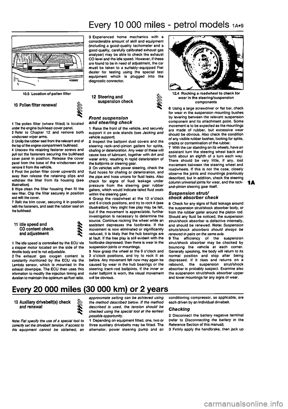
1 The pollen filter (where fitted) is located under the engine bulkhead cover panel. 2 Refer to Chapter 12 and remove both svindscreen wiper arms. 3 Unclip the rubber
seal
from the relevant end of
the
top of the engine compartment bulkhead. 4 Unscrew the retaining fastener screws and pull out the fasteners securing the bulkhead cover panel in position. Release the cover panel Irom the base of the windscreen and remove it from the vehicle. 5 Pivot the pollen filter cover upwards and away then release the retaining clips and withdraw the filter from its housing (see illustration). 6 Wipe clean the filter housing then fit the new filter. Clip the filter securely in position and refit the cover. 7 Refit the trim cover, securing it in position with Ihe fasteners, and seat the rubber seal on
the
bulkhead.
11 Idle speed and ^
CO
content check J and adjustment ^
1 The idle speed is controlled by the ECU via a stepper motor located on the side of the throttle body and is not adjustable. 2 The exhaust gas oxygen content is constantly monitored by the ECU via the Lambda sensor, which is mounted in the exhaust down pipe. The ECU then uses this information to modify the injection timing and duration to maintain the optimum air/fuel ratio.
3 Experienced home mechanics with a considerable amount of skill and equipment (including a good-quality tachometer and a good-quality, carefully calibrated exhaust gas analyser) may be able to check the exhaust CO level and the idle speed. However, if these are found to be in need of adjustment, the car must be taken to a suitably-equipped Fiat dealer for testing using the special test equipment which is plugged into the diagnostic connector.
12 Steering and ^ suspension check
front suspension and steering check 1 Raise the front of the vehicle, and securely support it on axle stands (see Jacking and
vehicle support).
2 Inspect the balljoint dust covers and the steehng rack-and-pinion gaiters for spirts, chafing or deterioration. Any wear of these will cause loss of lubricant, together with dirt and water entry, resulting in rapid deterioration of the balljoints or steering gear. 3 On vehicles with power steering, check the fluid hoses for chafing or deterioration, and the pipe and hose unions for fluid leaks. Also check for signs of fluid leakage under pressure from the steering gear rubber gaiters, which would indicate failed fluid seals within the steering gear. 4 Qrasp the roadwheel at the 12 o'clock and 6 o'clock positions, and try to rock it (see illustration). Very slight free play may be felt, but if the movement is appreciable, further investigation Is necessary to determine the source. Continue rocking the wheel while an assistant depresses the footbrake. If the movement is now eliminated or significantly reduced, it is likely that the hub bearings are at fault. If the free play is still evident with the footbrake depressed, then there is wear in the suspension joints or mountings. 5 Now grasp the wheel at the 9 o'clock and 3 o'clock positions, and try to rock it as before. Any movement felt now may again be caused by wear in the hub bearings or the steering track-rod balljoints. If the inner or outer balljoint is worn, the visual movement will be obvious.
12.4 Rocking a roadwheel to check for wear in the steering/suspension components 6 Using a large screwdriver or flat bar, check for wear in the suspension mounting bushes by levering between the relevant suspension component and its attachment point. Some movement is to be expected as the mountings are made of rubber, but excessive wear should be obvious. Also check the condition of any visible rubber bushes, looking for splits, cracks or contamination of the rubber. 7 With the car standing on its wheels, have an assistant tum the steering wheel back and forth about sn eighth of a turn each way. There should be very little, if any. lost movement between the steering wheel and roadwheels. If this is not the case, closely observe the joints and mountings previously described, but in addition, check the steering column universal joints for wear, and the rack-and-pinion steering gear itself.
Suspension strut/ shock absorber check 8 Check for any signs of fluid leakage around the suspension strut/shock absorber body, or from the rubber gaiter around the piston rod. Should any fluid be noticed, the suspension strut/shock absorber is defective internally, and should be renewed. Note: Suspension struts/shock absorbers should always be renewed in pairs on the same axle. 9 The efficiency of the suspension strut/shock absorber may be checked by bouncing the vehicle at each corner. Generally speaking, ihe body will return to its normal position and stop after being depressed. If it rises and returns on a rebound, the suspension strut/shock absorber is probably suspect. Examine also the suspension strut/shock absorber upper and lower mountings for any signs of wear.
Every 20 000 miles (30 000 km) or 2 years
13 Auxiliary drivebelt{s) check % and renewal ^
Note: Fiat specify the use of a special tool to cooectfyset the drivebelt tension. If access to ibis equipment cannot be obtained, an
approximate setting can be achieved using the method described below. If the method described is used, the tension should be checked using the special tool at the earliest possible opportunity. 1 Depending on equipment fitted, one. two or three auxiliary drivebelts may be fitted. The alternator, power steering pump and air
conditioning compressor, as applicable, are each driven by an Individual drivebelt.
Checking 2 Disconnect the battery negative terminal (refer to Disconnecting the battery in the Reference Section of this manual). 3 Firmly apply the handbrake, then jack up
Page 73 of 225
2C«1
Chapter 2 PartC:
Diesel engine in-car repair procedures
Contents
Auxiliary drivebelts - removal and refitting See Chapter 1B Camshaft cover - removal and refitting 6 Camshaft oil seal - renewal 7 Camshaft - removal and refitting See Chapter 20 Crankshaft oil seats - renewal 8 Cylinder compression test « 3 Cylinder head - dismantling and overhaul See Chapter 20 Cylinder head - removal and refitting 9 Engine mountings - inspection and renewal 11 Engine oil and fitter - renewal See Chapter 18 Engine oil level check See Weekly checks
Degrees of difficulty
Flywheel * removal, inspection and refitting 10 General information 1 Location of TDC on No 1 cylinder 2 Oil cooler - removal and refitting 14 Oil pump and pick-up tube • removal, Inspection and refitting 13 Sump • removal and refitting 12 Timing belt and covers • removal and refitting 4 Timing belt tensioner and sprockets - removal, Inspection and refitting 5 Valve clearance check and adjustment See Chapter 1B
Easy,
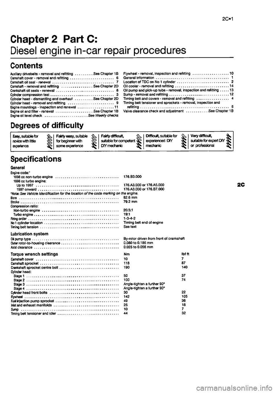
suitable for novice
with Irttle
|| experience g^
FaMy
eesy,
suitable ^
forbeglnnerwilti
some experience ^
Falrtydfficult, ^ suitable
for
competent DIYmechanic ^
Difficult, suitable
for & experienced DIY mechanic ^
Very
difficult,
^ suitable
for
expert
DfY
jR or professional ^
Specifications
General Engine code:' 1698 cc non-turbo engine 176.B3.000 1698 cc turbo engine: Up to 1997 t76.A3.00aor176.A5.000 1997 onward 176.A3.000or176.B7.000 •Note: See Vehicle Identification for the location of the code marking on the engine. Bore 82.6 mm Stroke 79.2 mm Compression ratio: Non-turbo engine 20.5:1 Turbo engine 19:1 Firing order 1-3-4-2
No 1
cylinder location Timing belt end of engine Titling belt tension See text
Lubrication system Oi pump type By-rotor driven from front of crankshaft Outer rotor-to-houslng clearance 0.080 to 0.186 mm Axial clearance 0.025 to 0.056 mm
Torque wrench settings Nm ibf ft Camshaft cover 10 7 Camshaft sprocket 11B 87 Crankshaft sprocket centre bolt 190 140 Cylinder head: Stage 1 50 37 Stage 2 100 74 StageS Angle-tighten a furtfier 90" Stage 4 Angle-tighten a further 90° CySnder head front bolts 30 22 Flywheel 142 105
Fuel
injection pump sprocket 49 36 Inlet and exhaust manifolds 25 18 Sump 10 7 Timing belt tensioner and idler 44 32
Page 80 of 225
2C*2 Diesel engine in-car repair procedures
Refitting 6 Locate a new gasket on the cylinder head and make sure tt Is correctly seated. 7 Lower the cover onto the gasket making sure the gasket Is not displaced, 8 Insert the mounting bolts and tighten them securely In a progressive sequence. Position Ihe support brackets as noted during removal. 9 Clip ihe coolant hoses in position then refil the air ducting.
7 Camshaft oil seal -renewal
8 Crankshaft oil seals -renswal I
9 Cylinder head -
removal
and refitting
1 Remove the timing belt and camshaft sprocket as descnbed in Sections 4 and 5. 2 Using a suitable hooked instrument, remove tho oil seal from the cylinder head taking care nol to damage the surface of the camshafl. Alternatively drill a small hole In tho oil seal and Insert a self-topping screw - the seal can then be removed by pulling on the screw with a pair of pliers. 3 Clean the seating In the cylinder head and tho end of the camshaft To prevent damage to the new oil seal as It is being fitted, wrap some adhesive tape around the end ol the camshaft and lightJy oil it. 4 Dip tho new ail s«al In oil then locate it over Ihe camshaft making sure that the sealing lips are facing inwards. 5 Using a suitable tubular drift, drive the oil seal squarely into the cylinder h*ad. Remove the adhesive tap© 6 Refit the camshaft sprocket and timing belt with reference to Sections 6 and 4.
Front (right-hand side) oil seal t The front oil seal is located in the oil pump casing on the front of the crankshaft. Remove the timing belt as described in Section 4 and the crankshaft sprocket as described in Section 5, 2 Using a suitable hooked instrument, remove the oil seal from the oil pump casing taking care not to damage the surface of the crankshaft. Alternatively drill a small hole In the oil soal and insert a self-tapping screw - the seal can then be removed by pulling on the screw with a pair of pliers. 3 Clean the seating in the oH pump and the surface of the crankshaft. To prevent damage to the new off seal as It Is being fitted, wrap some adhesive tape around the end of tha crankshaft and lightly oil it. 4 Oip the new oii seal In oil then otter it up to the oil pump casing making sure that the sealing Hps are facing inwards,
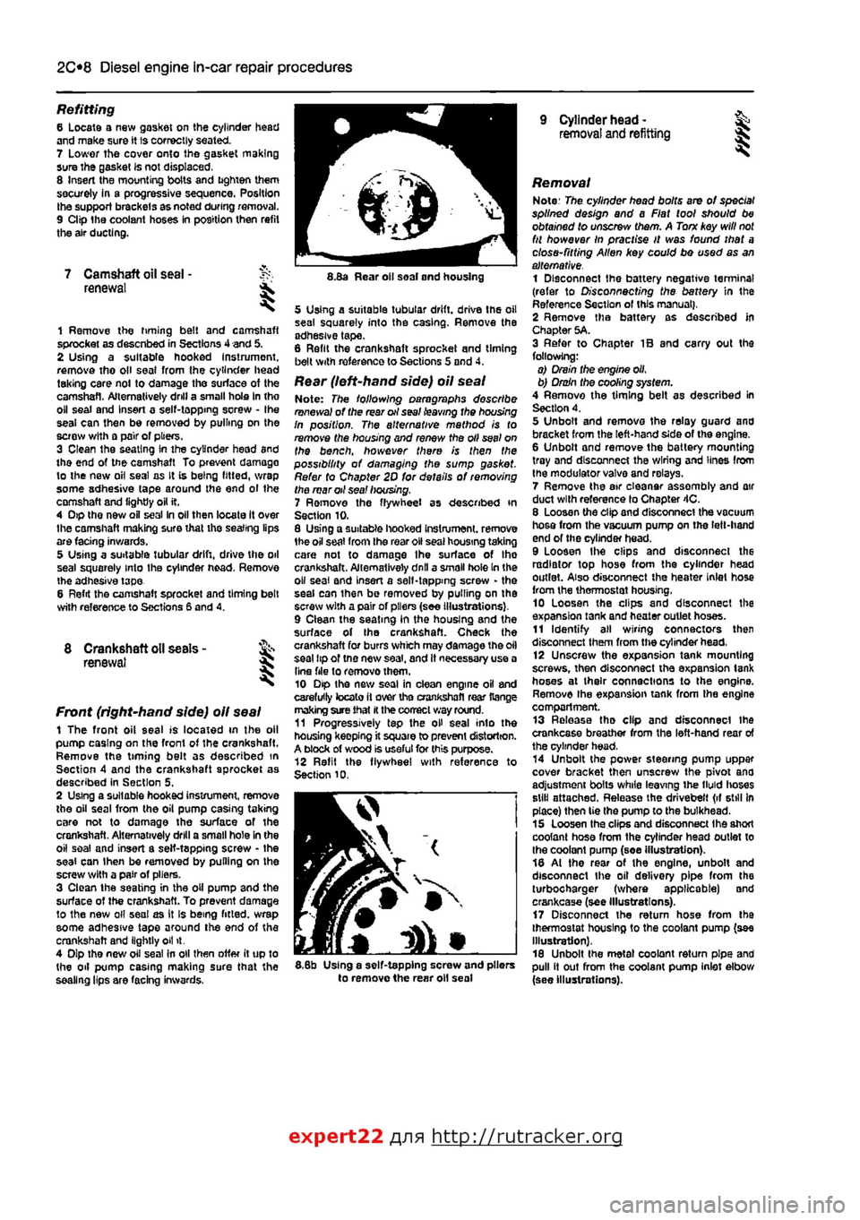
8.Ba Rear oil soal and housing
5 Using a suitable tubular drift, driva the oil sea! squarely into the casing. Remove the adhesive tape. 6 Refit the crankshaft sprocket and timing belt with reference to Sections 5 and 4.
Rear (left-hand side) oil seal Note: The following paragraphs describe renewal of the rear oil seal leaving the housing In position. The alternative mathod is to remove the housing and renew the oil seel on the bench, however there is then the possibility of damaging the sump gasket. Refer to Chapter 2D for details of removing the mar oil sea! housing. 7 Ramove the flywheel as described in Section 10. 8 Using a suitable hooked Instrument. remove 1he oil seat from the roar oil seal housing taking care not to damage Ihe surface of Ihe crankshaft. Alternatively dnll a small hole In the o» seal and insert a self-tapping screw - the seal can ihan be removed by pulling on the screw with a pair of pliers (see Illustrations), 9 Clean the seating in the housing and the surface of the crankshaft. Check the crankshaft for burrs which may damage the oil seal tip of tno new saal, and It necessary use a Una file to removothem. 10 Dip the new soal in clean engine oil and carefully tocato it over tho crankshafl rear Range making sure that
H
the correct way round. 11 Progressively tap the oH seal into the housing keepfng it square to prevent distortion. A block of wood is useful for this purpose. 12 Refit the flywheel with reference to Section 10.
I
5.8b Using a self-tapping screw and pliers to remove the rear oil seal
Removal Note: The cylinder head bolts are of special splined design and a Fiat tool should be obtained to unscrew them. A Torn key will
not
fit however In practise It was found that a close-fitting Allen key could bo used as an alternative. 1 Disconnect the battery negative terminal (refer to Disconnecting the battery in the Reference Section of this manual), 2 Remove tha battery as described In Chapter 5A. 3 Refer to Chapter IB and carry out the following: o) Drain the engine oil, b) Drain the cooling system. 4 Remove the timing belt as described in Section 4. 5 Unbolt and remova the relay guard and bracket from the left-hand side of the engine. 6 Unbolt and remove the battery mounting tray and disconnect the wiring and lines from the modulator valva and relays. 7 Remove the air eleanar assembly and air duct with reference lo Chapter 4C. 8 Loosen the clip and disconnect the vacuum hosa from the vacuum pump on the left-hand end of the cylinder head. 9 Loosen Ihe clips and disconnect the radiator top hose from the cylinder head outlet. Also disconnect the heater inlet hose from the thermostat housing, 10 Loosen the clips and disconnect the expansion tank and heater outlet hoses. 11 Identify all wiring connectors then disconnect them from the cylinder head, 12 Unscrew the expansion tank mounting screws, then disconnect tha expansion tank hoses at their connections to the engine. Remove the expansion tank from tha engine compartment. 13 Release tha clip and disconnect ihe crankcase breather from the left-hand rear of the cylinder head. 14 Unbolt the power steering pump uppar cover bracket then unscrew the pivot ana adjustment bolts while leaving ihe tMd lioses still attached. Release the drivebelt (if still In place) then tie the pump to the bulkhead. 15 Loosen tha clips and disconnect Ihe short coolant hose from the cylinder head outlet to the coolant pump (soe illustration). 18 At the rear of the engine, unbolt and disconnect the oil delivery pipe from the turbocharger (where applicable) and crankcase (see Illustrations). 17 Disconnect the return hose from tha thermostat housing to the coolant pump (see Illustration), 18 Unbolt the metal coolant return pipe and pull it out from the coolant pump inlet elbow (see Illustrations).
expert22 flna http://rutracker.org
Page 125 of 225
Ihe right-hand front roadwheel and the protective plastic cover under the wheelarch. 37 Disconnect the sensor wiring plug on the front of the engine. 38 Detach the sensor from its mounting. Refitting 39 After refitting Ihe sensor use a feeler blade to check that the gap between sensor and the serrated part of the crankshaft pulley Is between 0.5 and 1.S mm. No adjustment is possible and if the gap is incorrect the sensor and pulley should be checked for possible damage.
Electronic control unit (ECU)
Removal Note: 77ie engine management system has a (earning capability which allows the ECU to store details of the engine's running
characteristics
in its memory,
This
memory
will
tie erased by the disconnection of the battery
cables,
with the resuit that the engine may idle
roughly,
or lack performance for a while, until
the
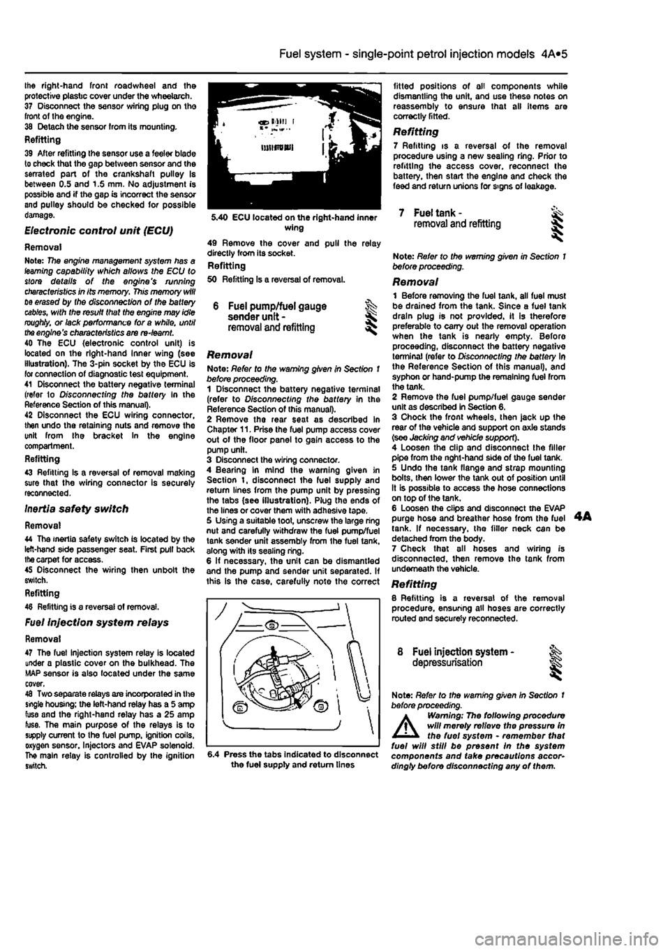
engine's characteristics are re-teamt. 40 The ECU {electronic control unit) is located on the right-hand Inner wing (see illustration). The 3-pin socket by the ECU is for connection of diagnostic test equipment. 41 Disconnect the battery negative terminal (refer to D/sconnecffng the battery in the Reference Section of this manual). 42 Disconnect the ECU wiring connector, then undo the retaining nuts and remove the unit from the bracket In the engine compartment. Refitting 43 Refitting Is a reversal of removal making sure that the wiring connector is securely reconnected. Inertia safety switch
Removal 44 The inertia safety switch is located by the left-hand side passenger seat. First pull back
the
carpet for access. 45 Disconnect the wiring then unbolt the switch. Refitting 48 Refitting is a reversal of removal.
Fuel injection system relays
Removal 47 The fuel injection system relay is located under a plastic cover on the bulkhead. The MAP sensor is also located under the same cover. 48 Two separate relays are incorporated in the single housing; the left-hand relay has a 5 amp fuse and the right-hand relay has a 25 amp fuse. The main purpose of the relays is to supply current to the fuel pump, ignition coils, oxygen sensor. Injectors and EVAP solenoid. The main relay is controlled by the ignition switch.
4A*2 Fuel system - single-point petrol Injection models
6 Fuel pump/fuel gauge sender unit -removal and refitting
Removal Note: Refer to the warning given in Section 1 before proceeding. 1 Disconnect the battery negative terminal (refer to Disconnecting the battery in the Reference Section of this manual). 2 Remove the rear seat as described in Chapter 11. Prise the fuel pump access cover out of the floor panel to gain access to the pump unit. 3 Disconnect the wiring connector. 4 Bearing in mind the warning given in Section t, disconnect the fuel supply and return lines from the pump unit by pressing the tabs (see illustration). Plug the ends of the lines or cover them with adhesive tape. 5 Using a suitable toot, unscrew the large ring nut and carefully withdraw the fuel pump/fuel tank sender unit assembly from the fuel tank, along with its sealing ring. 6 If necessary, the unit can be dismantled and the pump and sender unit separated. If this is the case, carefully note the correct
fitted positions of oil components while dismantling the unit, and use these notes on reassembly to ensure that all items are correctly fitted.
Refitting 7 Refitting is a reversal of the removal procedure using a new sealing ring. Prior to refitting the access cover, reconnect the battery, then start the engine and check the feed and return unions for signs of leakage.
5.40 ECU located on the right-hand inner wing 49 Remove the cover and pull the relay directly from its socket. Refitting 50 Refitting Is a reversal of removal.
7 Fuel tank -removal and refitting
6.4 Press the tabs Indicated to disconnect the fuel supply and return tines
Note: Refer to the warning given in Section 1 before proceeding.
Removal 1 Before removing the fuel tank, all fuel must be drained from the tank. Since a fuel tank drain plug is not provided, it is therefore preferable to carry out the removal operation when the tank is nearly empty. Before proceeding, disconnect the battery negative terminal (refer to Disconnecting the battery In the Reference Section of this manual), and syphon or hand-pump the remaining fuel from the tank. 2 Remove the fuel pump/fuel gauge sender unit as described in Section 6. 3 Chock the front wheels, then jack up the rear of the vehicle and support on axle stands (see Jacking and vehicle support). 4 Loosen the clip and disconnect the filler pipe from the nght-hand side of the fuel tank. 5 Undo the tank flange and strap mounting bolts, then lower the tank out of position until It is possible to access the hose connections on top of the tank. 6 Loosen the clips and disconnect the EVAP purge hose and breather hose from the fuel tank. If necessary, the filler neck can be detached from the body. 7 Check that all hoses and wiring is disconnected, then remove the tank from underneath the vehicle. Refitting 8 Refitting is a reversal of the removal procedure, ensuring all hoses are correctly routed and securely reconnected.
8 Fuel injection system - ^ depressurisation
Note: Refer to the warning given In Section t before proceeding.
A
Warning; The following procedure will merely relievo the pressure in the fuel system • remember that fuel will still be present In the system components and take precautions accor-dingly before disconnecting any of them.
Page 140 of 225
Fuel system - diesel models
4C*3
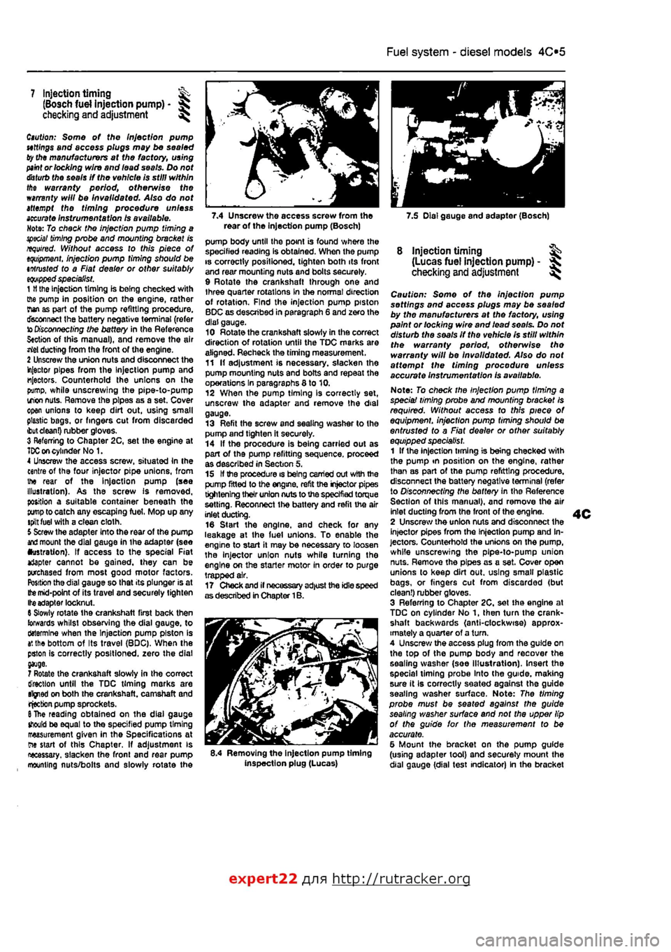
7.4 Unscrew the access screw from the 7.5 Dial gauge and adapter (Bosch) rear of the Injection pump (Bosch)
7 Injection timing ^ (Bosch fuel injection pump) -checking and adjustment ^
Caution: Some of the Injection pump uttlngs and access plugs may be sealed ty the manufacturers at the factory, using
paint
or locking wire and lead seals. Do not
disturb
the seals If the vehicle is still within the warranty period, otherwise the warranty will be invalidated. Also do not attempt the timing procedure unless
accurate
Instrumentation Is available. Note: To check the injection pump timing a special
timing
probe and mounting bracket is required. Without access to this piece of
tquipment.
injection pump timing should be intrusted to a Fiat dealer or other suitably
eqwpped
specialist. 1
H
the Injection timing is being checked with ffie pump in position on the engine, rather rian as part ot the pump refitting procedure, disconnect the battery negative terminal (refer to
Disconnecting
the battery in the Reference S«ction of this manual), and remove the air rtel ducting from the front of the engine. 2 Unscrew the union nuts and disconnect the injector pipes from the Injection pump and injectors. Counterhold the unions on the pump, while unscrewing the pipe-to-pump irion
nuts.
Remove the pipes as a set. Cover open unions to keep dirt out, using small plastic bags, or fingers cut from discarded
ibut clean!)
rubber gloves. 3 Referring to Chapter 2C, set the engine at
TDC on
cylinder No 1. 4 Unscrew the access screw, situated In the centre of the four injector pipe unions, from the rear of the Injection pump (see illustration). As the screw Is removed, position a suitable container beneath the
pump
to catch any escaping fuel, Mop up any tpilt fuel with a clean cloth. 5 Screw the adapter into the rear of the pump
and
mount the dial gauge in ihe adapter (see •ustration). If access to the special Fiat *Japter cannot be gained, they can be purchased from most good motor factors. Position the dial gauge so that its plunger is at
Ifce
mid-point of its travel and securely tighten Ite adapter locknut. 6 Slowly rotate the crankshaft first back then towards whilst observing the dial gauge, to ctotermlne when the Injection pump piston is
a',
the bottom of Its travel (BDC), When the pston Is correctly positioned, zero the dial
7 Rotate the crankshaft slowly in the correct direction until the TDC timing marks are tfjned on both the crankshaft, camshaft and rjecbon pump sprockets.
6
The reading obtained on the dial gauge should be equal to the specified pump timing measurement given in the Specifications at ew start of this Chapter, If adjustment is necessary, slacken the fronl and rear pump mounting nuts/bolts and slowly rotate the
pump body until the point is found where the specified reading Is obtained. When the pump is correctly posilioned, tighten both its front and rear mounting nuts and bolts securely. 9 Rotate the crankshaft through one and three quarter rotations in the normal direction of rotation. Find the injection pump piston BDC as described in paragraph 6 and zero the dial gauge. 10 Rotate the crankshaft slowly in the correct direction of rotation until the TDC marks are aligned. Recheck the timing measurement. 11 If adjustment is necessary, slacken the pump mounting nuts and bolts and repeat the operations In paragraphs 8 to 10. 12 When the pump timing Is correctly set, unscrew the adapter and remove the dial gauge. 13 Refit the screw and sealing washer to the pump and tighten it securely. 14 If the procedure is being carried out as part of the pump refitting sequence, proceed as described in Section 5, 15 If the procedure is being carried out with the pump fitted to the engine, refit the injector pipes tightening their union nuts to the specified torque setting. Reconnect the battery and refit the air inlet ducting. 16 Start the engine, and check for any leakage at the luel unions. To enable the engine to start it may be necessary to loosen the injector union nuts while turning tho engine on the starter motor in order to purge trapped air. 17 Check and if necessary adjust the idle speed as described in Chapter 1B.
8.4 Removing the injection pump timing inspection plug (Lucas)
8 injection timing ^ (Lucas fuel injection pump) - ^ checking
and
adjustment ^
Caution: Some of the injection pump settings and access plugs may be sealed by the manufacturers at the factory, using paint or locking wire and lead seo/s. Do not disturb the seals if the vehicle Is still within the warranty period, otherwise tho warranty will be Invalidated. Also do not affempf the timing procedure unless accurate instrumentation is available.
Note: To check the Injection pump timing a speciai timing probe and mounting bracket Is required. Without access to this piece of equipment, injection pump timing should be entrusted to a Fiat dealer or other suitably equipped specialist. 1 If the injection timing is being checked with the pump tn position on the engine, rather than as part of the pump refitting procedure, disconnect the battery negative terminal (refer to Disconnecting the battery in the Reference Section of this manual), and remove the air inlet ducting from the front of the engine. 2 Unscrew the union nuts and disconnect the injector pipes from the Injection pump and In-jectors. Counterhold the unions on the pump, while unscrewing the pipe-to-pump union nuts. Remove the pipes as a set. Cover open unions to keep dirt out. using smalt plastic bags, or fingers cut from discarded (but clean!) rubber gloves. 3 Referring to Chapter 2C, set the engine at TDC on cylinder No 1, then turn the crank-shaft backwards (anti-clockwise) approx-imately a quarter of a turn. 4 Unscrew the access plug from the guide on the top of the pump body and recover the sealing washer (soe Illustration). Insert the special liming probe Into the guide, making sure it Ib correctly seated against the guide seating washer surface. Note: The timing probe must be seated against the guide sealing washer surface and not the upper lip of the guide for the measurement to be accurate. 5 Mount the bracket on the pump guide (using adapter tool) and securely mount the dial gauge {dial test indicator) In the bracket
expert22 fl/i* http://rutracker.org
Page 141 of 225
Fuel system - diesel models 4C*3
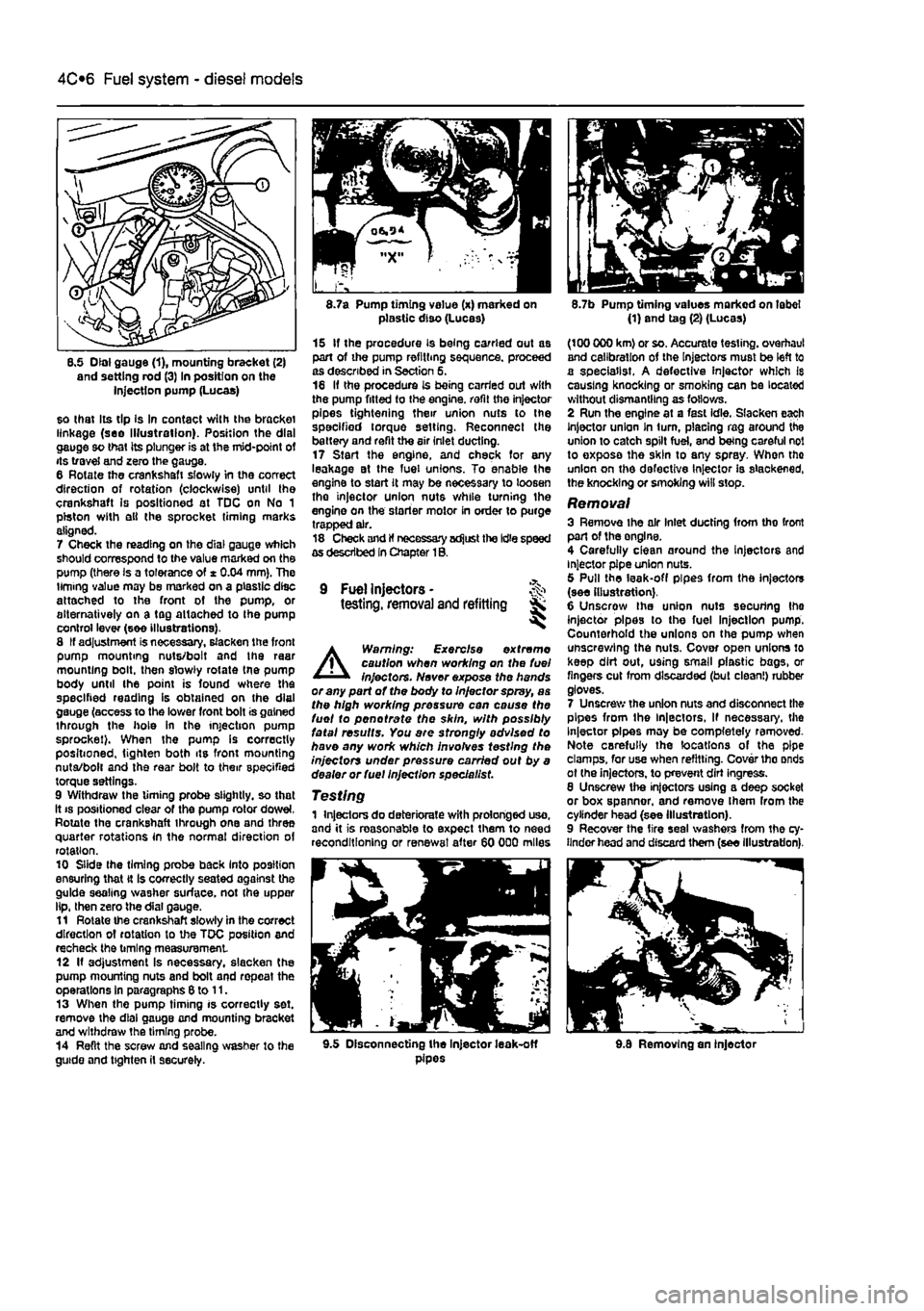
8.5 Dial gauge (1), mounting bracket (2) and setting rod (3) In position on the injection pump (Lucas)
so that Its tip Is In contact with the bracket linkage (see Illustration). Position the dial gauge so that its plunger is at the mid-point of its travel and zero the gauge. 6 Rotate the crankshaft slowly in the correct direction of rotation (clockwise) until the crankshaft is positioned at TDC on No 1 piston with ell the sprocket timing marks aligned. 7 Check the reading on the dial gauge which should correspond to the value marked on the pump (there is a tolerance of * 0.04 mm). The timing value may be marked on a plastic disc attached to the front of the pump, or alternatively on a tag attached to Ihe pump control lever (see illustrations). 8 If adjustment is necessary, slacken the front pump mounting nuts/bolt and the raar mounting bolt, then slowly rotate tne pump body until the point is found where the specified reading is obtained on the dial gauge (access to the lower front bolt is gained through the hole in the injection pump sprocket). When the pump Is correctly positioned, tighten both its front mounting nuta/bolt and the rear bolt to their specified torque settings. 9 Withdraw the timing probe slightly, so that it
8.7a Pump timing value (x) marked on plastic diso (Lucas)
15 If the procedure is being carried out as part of the pump refilling sequence, proceed as described in Section 5. 16 If the procedure is being carried out with the pump fitted to the engine, refit the injector pipes tightening their union nuts to the specified torque setting. Reconnect the battery and refit the air inlet ducting. 17 Start the engine, and check for any leakage at the fuel unions. To enable the engine to start it may be necessary to loosen tho injector union nuts while turning the engine on the starter motor in order to purge trapped air. 18 Check and If necessary adjust the Idle speed as described In Chapter 1B.
9 Fuel Injectors -testing, removal and refitting Sk ^
A
Warning: Exercise extreme caution when working on the fuel injectors. Never expose the hands or any part of the body to Injector spray, as the high working pressure can cause the fuel to pen ot rate the skin, with possibly fatal results. You are strongly advised to have any work which involves testing the injectors under pressure carried out by a dealer or fuel Injection specie list.
Testing 1 Injectors do deteriorate with prolonged uso, and it is reasonable to expect them to need reconditioning or renewal after 60 000 miles
8.7b Pump timing values marked on label (1) and tag (2) (Lucas)
(100 000 km) or so. Accurate testing, overhaul and calibration of the Injectors must be left to a specialist. A defective injector which Is causing knocking or smoking can be located without dismantling as follows. 2 Run the engine at a fast idle. Slacken each Injector union In turn, placing rag around the union to catch spilt fuel, and being careful not to exposa the skin to any spray. When tho union on the defective Injector is slackened, the knocking or smoking will stop.
Removal 3 Remove ihe air Inlet ducting from tho front part of the onglne. 4 Carefully clean around the Injectors and injector pipe union nuts. 5 Pull the leak-off pipes from the injectors (see illustration). 6 Unscrow the union nuts securing Ihe injector pipes to the fuel Injection pump. Counterhold the unions on the pump when unscrewing the nuts. Cover open unions lo keep dirt out, using small plastic bags, or fingers cut from discarded (but clean!) rubber gloves. 7 Unscrew the union nuts and disconnect the pipes from the ln|ectors, If necessary, the Injector pipes may be completely removed-Note carefully the locations of the pipe clamps, for use when refitting. Cover tho onds ot (he injectors, to prevent dirt ingress. 8 Unscrew the injectors using a deep socket or box spanner, and remove Ihem from the cylinder head (see Illustration). 9 Recover the tire seal washers from the cy-linder head and discard them (see illustration).
9.5 Disconnecting the Injector leak-off pipes 9.8 Removing an injector
Page 159 of 225
6*2 Clutch
3 Clutch cable -removal and refitting
Note: This procedure applies to models fitted with a cabfe-opemted dutch
release mechanism.
Removal 1 Remove the battery and tray as described In Chapter SA. If necessary, also remove the Inlet air ducting for Improved access as described In the relevant part of Chapter 4. 2 Unscrew the adjustment locknut and adjuster nut from the end of the cable fitting, (hen release the inner and outer cables from the transmission housing. Note the position of the damper biock. 3 Working Inside the vehicle, unhook the inner cable from the top of the clutch pedaL 4 Returning to the engine compartment, unscrew the nuts securing the outer cable to the bulkhead, then withdraw the cable assembly from the engine compartment. Refitting 5 Apply a smear of multi-purpose grease to the cable end fittings, then pass the cable through the bulkhead. Refit and tighten the nuts. 6 Inside the vehicle hook the inner cable onto the top of the clutch pedal. 7 in the engine compartment, attach the outer cable to the transmission housing and refit the damper block and nuts lo Ihe inner cable end. fi Adjust the cable as described in Section 2. 9 Refit the air ducting and battery with reference to Chapters 4 and 5A
4 Clutch hydraulic system -
i
Note: This procedure applies to models fitted with the hydraulicalty-operated clutch release mechanism.
A
Warning: Hydraulic fluid Is poisonous; thoroughly wash off spllfs from bare skin without delay. Seek Immediate medical advice If any fluid is swallowed or gets into the eyes. Certain types of hydraulic fluid are Inflammable and may ignite when brought into contact with hot components; when servicing any hydraulic system, It is safest to assume that the fluid IS Inflammable, and to take precautions against the risk of fire as though ft were petrof that was being handled. Hydraulic fluid Is an effective paint stripper and will also attack many plastics. If spillage occurs onto painted bodywork or fittings, ft should be washed off Immediately, using copious quantities of fresh water. It Is also hygroscopic - It can absorb moisture from the air, which then renders it useless. Old fluid may have
suffered contamination, and should never be re-used. When topping-up or renewing tho fluid, always use tha recommended grade, and ensure that It comes from a new seated container. General information 1 Whenever the clutch hydraulic lines are disconnected for service or repair, a certain amount of air will enter the system. The presence of air In any hydraulic system will Introduce a degree of elasticity, and in the clutch system this will translate into poor pedal feel and reduced travel, leading to inefficient gear changes and even clutch system failure. For this reason, the hydraulic lines must be sealed using hose clamps before any work la carried out and then on completion, topped up and bled to remove any air bubbles. 2 To seal off Ihe hydraulic supply to tha clutch slave cylinder, fit a proprietary brake hose clamp to the flexible section of the hose located over the transmission and tighten it securely. It will be necessary to remove the battery and battery tray to access the hose. 3 The most effective way of bleeding the clutch hydraulic system is to use a pressure brake bleeding kit. These are readily available in motor accessories shops and are extremely effective: the following sub-section describes bleeding the clutch system using such a kit. The alternative method is to bleed the system by depressing tho clutch pedal • refer to Chapter 9. Section 11, for details of this method.
Bleeding 4 Remove the protective cap from Ihe bleed nipple on the slave cylinder. Access can be improved by removing the battery and tray with reference to Chapter 5A. 5 Fit a ring spanner over the bleed nipple head, but do not slacken it at this point. Connect a length of dear plastic hose over the nipple and insert the other end into a clean container. Pour hydraulic fluid into the container, such that the end of the hose is covered. 6 Following the manufacturer's instructions, pour hydraulic fluid into the bleeding kit vessel 7 Unscrew the vehicle's fluid reservoir cap, then connect Ihe bleeding kit fluid supply hose to the reservoir. 8 Connect the pressure hose to a supply of compressed air - a spare tyre is a convenient source. Caution: Check that the pressure In the tyre does not exceed the maximum supply pressure quoted by the kit manufacturer, let soma sir escape to reduce the pressure, if necessary. Gently open the air valve and allow the air and fluid pressures to equalise. Check that there ere no teaks before proceeding. 9 Using the spanner, slacken the bleed pipe nipple until fluid and air bubbles can be seen to flow through the tube, into the container.
Maintain a steady flow until the emerging fluid la free of air bubbles; keep a watchful eye on the level of fluid in the bleeding kit vessel and the vehicle's fluid reservoir • if it Is allowed to drop too low, air may be forced into the system, defeating the object of the exercise. To refill the vessel, turn off the compressed air supply, remove the lid and pour In en appropriate quantity of clean fluid from a new container - do not re-use the fluid collected in the receiving container. Repeat as necessary until the ejected fluid is bubble-free. 10 On completion, pump the olutch pedal several times to assess its feel and travel. If firm, constant pedal resistance is not felt throughout the pedal stroke, it i6 probable that air Is still present in the system - repeat the bleeding procedure untii the pedal feel is restored. 11 Depressurise the bleeding kit and remove it from the vehicle. At this point, the fluid reservoir may be over-full; the excess should be removed using a clean pipette to reduce the level to the MAX mark. 12 Tighten the bleed pipe nipple using the spanner and remove the receiving container. Refit the protective cap. 13 On completion, assess the feel of the clutch pedal; if it exhibits any sponginess or looseness, further bleeding may be required. 14 Where removed, refit the battery and tray. 15 Finally, road test the vehicle and check the operation of the clutch system whilst changing up and down through the gsar9. whilst pulling away from a standstill and from a hill start.
5 Clutch master cylinder - & removal
and
refitting 5 S Note: This procedure applies to models
fitted
with the hydraulically-operated dutch
release
mechanism. Note: Refer to the warning at Ihe beginning
of
Section 4 regarding the hazards of
working
with hydraulic fluid.
Removal 1 Disconnect the battery negative terminal (refer lo Disconnecting the battery in the Reference Section of this manual). 2 Remove the air cleaner and air ducting as described in the relevant Part of Chapter 4. 3 For improved access on petrol engine models, remove the alternator as described In Chapter 5A. 4 Fit a brake hose clamp to the hose between the hydraulic fluid reservoir and the clutch master cylinder. Alternatively syphon ail the fluid from the reservoir. 5 Disconnect the fluid supply hose at the master cylinder, then unscrew the union nut and disconnect the hydraulic pipe from the cylinder outlet. Be prepared for some fluid loss by placing some rags beneath the master cylinder.
Page 187 of 225
Braking system 9®11
Bleeding • using a one-way valve kit 21 As their name implies, these kits consist ol a length of tubing with a one-way valve Fitted, to prevent expelled air and fluid being drawn back into the system; some kits include a translucent container, which can be positioned so that the air bubbles can be more easily seen flowing from the end of the tube. 22 The kit is connected to the bleed screw, which is then opened. The user returns to the driver's seat, depresses the brake pedal with a smooth, steady stroke, and stowty releases it; this is repeated until the expelled fluid is clear of air bubbles. 23 Note that these kits simplify work so much that It is easy lo forget the master cylinder reservoir fluid level; ensure that this Is maintained at least above the MIN level line at all times.
Bleeding -using a pressure-bleeding kit 24 These kits are usually operated by the reservoir of pressurised air contained in the spare tyre. However, note that it will probably be necessary to reduce the pressure lo a lower level than normal; refer to the instructions supplied with the kit. 2$ By connecting a pressurised, fluid-filled container to the master cylinder reservoir, bleeding can be carried out simply by opening each screw In turn (in the specified sequence), and allowing the fluid to flow out until no more air bubbles can be seen in the expelled fluid. 28 This method has the advantage that the large reservoir of fluid provides an additional safeguard against air being drawn into the system during bleeding. 27 Pressure-bleeding is particularly effective when bleeding 'difficult' systems, or when bleeding the complete system at the time of routine fluid renewal.
All methods 28 When bleeding is complete, and firm pedal feel is restored, wash off any split fluid, lighten the bleed screws securely, and refit their dust caps (where applicable). 29 Check the hydraulic fluid level in the master cylinder reservoir, and top-up if necessary. 30 Discard any hydraulic fluid thai has been Wed from the system; it will not be fit for re-use. 91 Check the feel of the brake pedal. If it feels at all spongy, air must still be present in Vie system, and further bleeding is required. Failure to bleed satisfactorily after a reasonable repetition of the bleeding procedure may be due to worn master cylinder seals.
12 Master cylinder- % removal
and
refitting SK
A
Warning: 8efore starting work, refer to the warning at the beginning of Section 11 concerning the dangers of hydraulic fluid.
Removal 1 Remove the master cylinder fluid reservoir cap, and syphon the hydraulic fluid from the reservoir. Note: Do not syphon the fluid by mouth, as It Is poisonous; use a syringe or an old poultry baster. Alternatively, open any convenient bleed screw In the system, and gently pump the brake pedal to expel (he fluid through a tube connected to the screw (see Section 11). Disconnect the wiring connector from the brake fiuld level sender unit. 2 Carefully prise the fiuld reservoir from the seals and release it from the top of the master cylinder. 3 Wipe clean Ihe area around the brake pipe unions on the side of the master cylinder, and place absorbent rags beneath the pipe unions to catch any surplus fluid. Make a note of the correct fitted positions of the unions, then unscrew the union nuts and carefully withdraw the pipes. Plug or tape over the pipe ends and master cylinder orifices, to minimise the loss of brake fluid, and to prevent the entry of dirt into the system. Wash off any spilt fluid immediately with cold wafer.
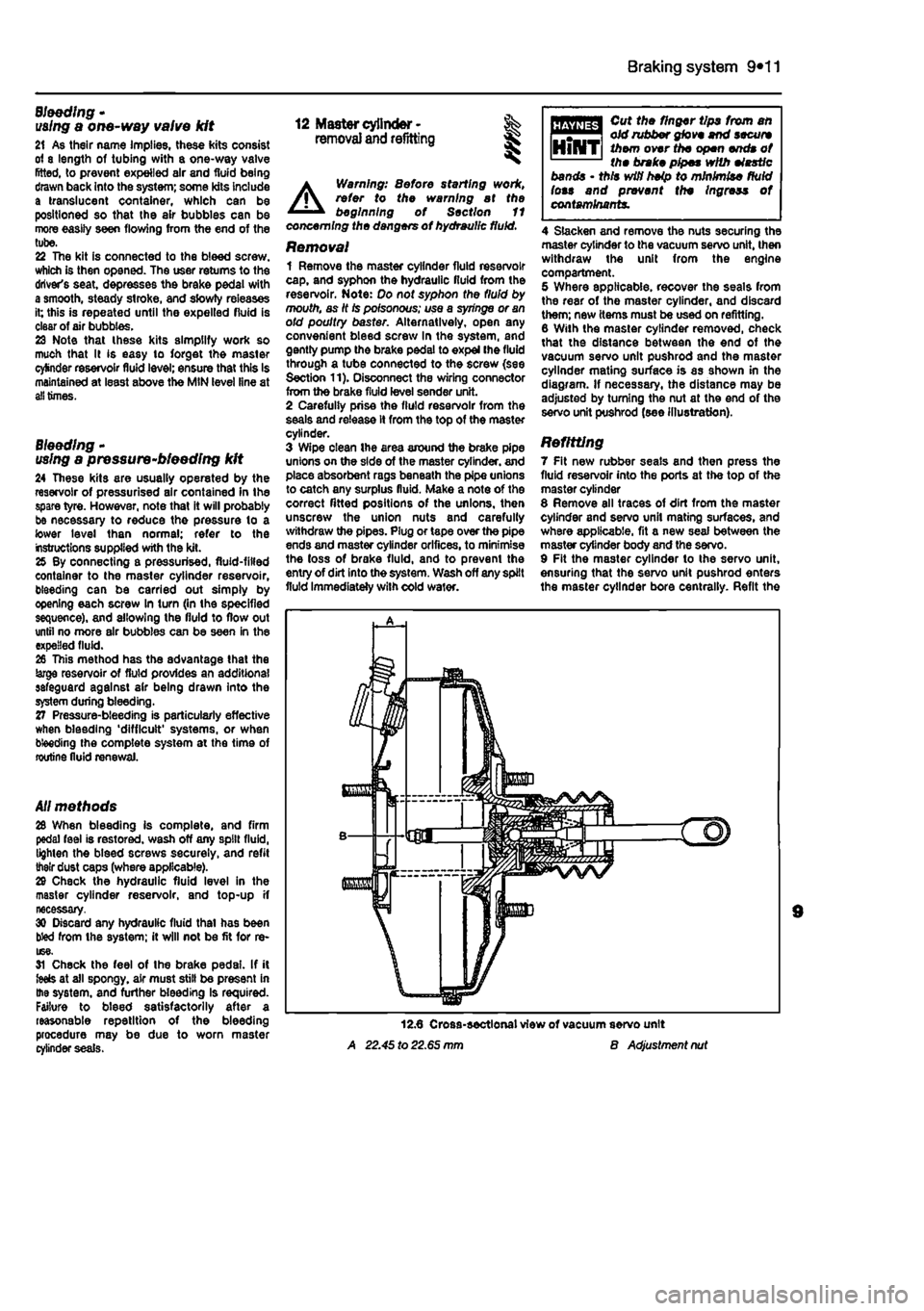
A 22.45 to 22.65 mm
Cut the finger tips from an old rubber glove end secure them over the open ends of the brake pipes with elastic bands • this wifi heip to minimise fluid lots and prevent the Ingress of contaminants.
4 Slacken and remove the nuts securing the master cylinder to the vacuum servo unit, then withdraw the unit from the engine compartment. 5 Where applicable, recover the seals from the rear of the master cylinder, and discard them; new items must be used on refitting. 8 With the master cylinder removed, check that the distance between the end of the vacuum servo unit pushrod and the master cylinder mating surface is as shown in the diagram. If necessary, the distance may be adjusted by turning the nut at the end of the servo unit pushrod (see illustration).
Refitting 7 Fit new rubber seals and then press the fluid reservoir into the ports at the top of the master cylinder 8 Remove all traces of dirt from the master cylinder and servo unit mating surfaces, and where applicable, fit a new seal between the master cylinder body and the servo. 9 Fit the master cylinder to the servo unit, ensuring that the servo unit pushrod enters the master cylinder bore centrally. Refit the
B Adjustment nut
Page 196 of 225
Suspension and steering 10*8
9.1 Prise the horn centre pad from the steering wheel hub unbolt the lower end of the damper from the trailing arm. 9 Lower the trailing arm gradually using a trolley jack, until the coil spring Is released from its lower seat on the trailing arm and its upper seat on the subframe. Make a note of the orientation of the coll spring, to aid correct refitting later. Refitting 10 Refitting is a reversal of removal, lighten the damper lower retaining bolt to the specified torque. Trailing arm Note: The rear stub axles are integral with the trailing arm assemblies and cannot be renewed separately. Removal 11 With reference to Chapter 9. carry out the following: a) Remove the brake drum, shoes and adjuster assembly. b) Unbolt the brake hose union from the
rear
of the wheel cylinder. c) Unbolt the brake pipe mounting bracket from the trailing arm. 12 Refer to Section 7 and remove The rear hub and beanng assembly. 13 With reference to the relevant sub-Section, unbolt the lower end of Ihe damper from the trailing arm. 14 Raise the trailing arm using a trolley jack so that the coll spring Is compressed, then slacken and withdraw the trailing arm front mounting bolL 15 With reference to the previous sub-Section, gradually lower the trailing arm using a trolley lack and remove the coll spring. 16 Allow Ihe trailing arm to hang down, then pull the leading edge of the arm down from its mounting bracket. Refitting 17 Refitting Is a reversal of removal. Tighten all suspension fixings to the specified torque settings, but delay this operation until the full weight vehicle is resting on the roadwheeis -this prevents the damper and trailing arm bushes from being strained. 18 On completion, bleed the brake hydraulic system and adjust the operation of the handbrake, with reference to Chapter 9.
9.2 Unplug the wiring from the centre pad at the connector(s)
9 Steering wheel - % removal and refitting ^
Note: This procedure does not apply to vehicles fitted with an airbag A Warning: For safety reasons, owners are strongly advisod to entrust to an authorised Fiat dealer any work which involves disturbing the airbeg system components. The airbag inflation devices contain explosive material and legislation exists to control their handling and storage. In addition, specialised test equipment Is needed to check thet the alrbag system Is fully operational following reassembly.
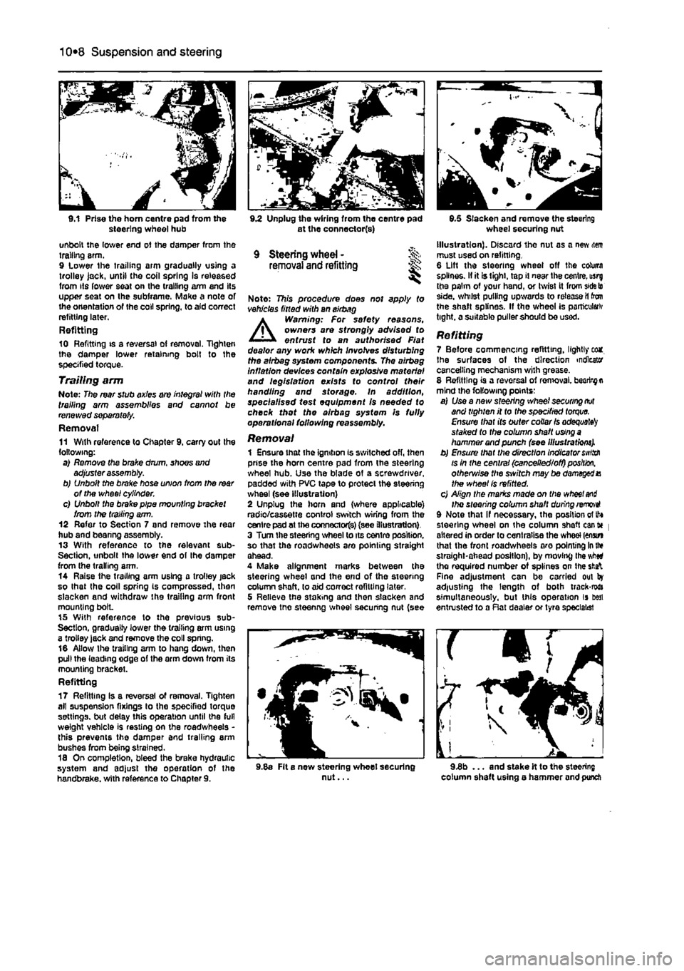
Removal 1 Ensure that the ignition is switched off, then prise the horn centre pad from the steering wheel hub. Use the blade of a screwdriver, padded with PVC tape to protect the steering wheel (see illustration) 2 Unplug the horn and (where applicable) radio/cassette control switch wiring from the centre pad at the connectors) (see illustration) 3 Turn the steering wheel to its centre position, so that the roadwheeis are pointing straight ahead. 4 Make alignment marks between the steering wheel and the end of the steering column shaft, to aid correct refitting later, 5 Relieve the staking and then slacken and remove tne steenng wheel securing nut (see
9.5 Slacken and remove the steering wheel securing nut Illustration). Discard the nut as a new item must used on refitting. 6 Lift the steering wheel off the column splines. If it is tight, tap il near the centre, usrg the palm of your hand, or twist it from
side to
side, whilst pulling upwards to release il ton the shaft splines. If the wheel is particular tight, a suitable puller should be used.
Refitting 7 Before commencing refitting, lightly eca. Ihe surfaces of the direction indicator cancelling mechanism with grease. 8 Refitting is a reversal of ren>oval.
bearing a
mind the following points: a) Use a new steering wheel
securing not
and tighten it to the specified
torque.
Ensure that its outer collar
Is adequate^
staked to the column shaft
using a
hammer and punch (see Illustrations). b) Ensure that the direction Indicator
swiith
is in the central (cancelled/off)
position,
otherv/ise the sivitch may be damaged X the wheel Is refitted. c) Align the marks made on the
wheel and
Ihe steering column shaft during removeI 9 Note that if necessary, the position of tf* steering wheel on the column shaft cant* | altered in order to centralise the wheel (enstn that the front roadwheeis aro pointing
In the
straight-ahead position), by moving the vMti the required number of splines on the
sfcafc
Fine adjustment can be carried out by adjusting the length of both track-rwa simultaneously, but this operation is best entrusted to a Rat dealer or tyre specialist
9.8a Fit a new steering wheet securing nut... 9.3b ... and stake it to the steering column shaft using o hammer and punch
Page 201 of 225
Suspension and steering 10*13
the skill required to use It properly, the checking and adjustment of these settings Is best left to a Fiat dealer or similar expert. Most tyre-fitting shops now possess sophisticated checking equipment. 3 For accurate checking, the vehicle must be at the kerb weight specified in Dimensions and weights. 4 Before starting work, check first that the tyre sizes and types are as specified (see Tyre pressures in Weekly checks), then check tyre pressures and tread wear. Also check roadwheel run-out, the condition of the hub bearings, the steering wheel free play and the condition of the front suspension components (Steering and suspension check in Chapter 1A or
1B).
Correct any faults found. 6 Park the vehicle on level ground, with the front roadwheeis in the straight-ahead position. Rock the rear and front ends to settle the suspension. Release the handbrake and roll the vehicle backwards approximately 1 metre, then forwards again, to relieve any stresses in the steering and suspension components. 6 Two methods are available to the home mechanic for checking the front wheel toe setting. One method is to use a gauge to measure the distance between the front and rear inside edges of the roadwheeis. The other method is to use a scuff plate, in which each front wheel is rolled across a movable plate which records any deviation, or scuff, of the tyre from the straight-ahead position as It moves across the plate. Such gauges are available in relatively-inexpensive form from accessory outlets. It Is up to the owner to decide whether the expense is justified, In view of the small amount of use such equipment would normally receive. 7 Prepare the vehicle 8S described in paragraphs 3 to 5 above.
8 If the measurement procedure is being used, carefully measure the distance between the front edges of the roadwheel rims and the rear edges of the rims. Subtract the front measurement from the rear measurement, and check that the result is within the specified range. If not, adjust the toe setting as described in paragraph 10. 9 If scuff plates are to be used, roll the vehicle backwards, check that the roadwheeis are in the straight-ahead position, then roll it across the scuff plates so that each front roadwheel passes squarely over the centre of its respective plate. Note the angle recorded by the scuff plates. To ensure accuracy, repeat the check three times, and take the average of the three readings, if the roadwheeis are running parallel, there will of course be no angle recorded; If a deviation value Is shown on the scuff plates, compare the reading obtained for each wheel with that supplied by the scuff plate manufacturers. If the value recorded is outside Ihe specified tolerance, the toe setting is incorrect, and must be adjusted as follows. Adjustment 10 Apply the handbrake, then jack up the front of the vehicle and support it securely on axle stands (see Jacking and vehicle support). Turn the steering wheel onto full-left lock, and record the number of exposed threads on the right-hand track-rod. Now turn the steering onto full-right lock, and record the number of threads on the left-hand side. If there are the same number of threads visible on both sides, then subsequent adjustment should be made equally on both sides. If there are more threads visible on one side than the other, it will be necessary to compensate for this during adjustment Note: It is important to ensure that, after adjustment, the same number of threads are visible on the end of each track-rod.
11 First clean the track-rod threads; If they are corroded, apply penetrating fluid before starting adjustment. Release the steering gear rubber gaiter outboard clips, then peel back the gaiters and apply a smear of grease, so that both gaiters are free and will not be twisted or strained as their respective track-rods are rotated. 12 Use a straight-edge and a scriber or similar to mark the relationship of each track-rod to the track-rod end. Working on each track-rod end in tum, unscrew its locking nut. 13 Alter the length of the track-rods, bearing In mind the note in paragraph 10, by screwing them into or out of the track-rod ends. Rotate the track-rod using an open-ended spanner fitted to the flats provided. If necessary, counterhold the track-rod end using a second spanner. Shortening the track-rods (screwing them Into their track-rod ends) will reduce toe-in and increase toe-out. 14 When the setting Is correct, hold the track-rods and securely tighten the locking nuts. Check that the balljoints are seated correctly In their sockets, and count the exposed threads on the ends of the track-rods. If the number of threads exposed is not the same on both sides, then the adjustment has not been made equally, and problems will be encountered with tyre scrubbing in turns; also, the steering wheel spokes will no longer be horizontal when the wheels are in the straight-ahead position. 15 When the track-rod lengths are the same, lower the vehicle to the ground and re-check the toe setting; readjust if necessary. When the setting is correct, tighten the locking nuts. Ensure that the steering gear rubber gaiters are seated correctly and are not twisted or strained, then secure them In position with new retaining clips.
10