Stop light FIAT PUNTO 1996 176 / 1.G User Guide
[x] Cancel search | Manufacturer: FIAT, Model Year: 1996, Model line: PUNTO, Model: FIAT PUNTO 1996 176 / 1.GPages: 225, PDF Size: 18.54 MB
Page 143 of 225
Fuel system - diesel models 4C*3
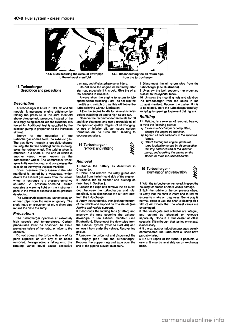
14.6 Nuts securing the exhaust downpipe to the exhaust manifold 14.8 Disconnecting the oil return pipe from tho turbocharger
13 Turbocharger -description and precautions
Description A turbocharger 1$ fitted to TDS, TD and SX models. It increases engine efficiency by raising the pressure In the inlet manifold above atmospheric pressure. Instead of the air simply being sucked Into the cylinders. It Is forced in. Additional fuel is supplied by the injection pump in proportion to the increased air inlet. Energy for the operation of the turbocharger comes from the exhaust gas. The gas flows through a specially-shaped housing (the turbine housing) and In so doing, spins the turbine wheel. The turbine wheel is attached lo a shaft, at the end of which is another vaned wheel known as the compressor wheel, The compressor wheel spins in Its own housing, snd compresses the inlet air on the way to the inlet manifold. Boost pressure (the pressure in the Inlet manifold) is limited by a wastegate, which diverts Ihe exhaust gas away from the turbine wheel In response to a pressure-sensitive actuator. A pressure-operaled switch operates a warning light on the instrument panel in the event of excessive boost pressure developing. The turbo shaft is pressure-lubricated by an oil feed pipe from the main oil gallery The shaft floats on a cushion of oil. A drain pipo returns the oil to the sump.
Precautions The turbocharger operates at extremely high speeds and temperatures. Certain precautions must be observed, to avoid premature failure of the turbo, or injury to the operator. Do not operate the turbo with any of its parts exposed, or with any of ils hoses removed. Foreign objects falling onto the rotating vanes could cause excessive
damage, and (if ejected) personal injury. Do not race the engine immediately after start-up, especially if it Is cold. Give the oil a few seconds lo circulate. Always allow the engine to return to idle speed before switching il off - do not blip the throttle and switch off, as this will leave the turbo spinning without lubrication. Allow the engine to idle lor several minutes before switching off after a high-speed run. Observe the recommended intervals for oil and filter changing, and use a reputable oil of the specified quality. Neglect of oil changing, or use of Inferior oil, can cause carbon formation on the turbo shaft, leading to subsequent failure.
14 Turbocharger -removal and refitting
8 Disconnect the oil return pipe from the turbocharger (see Illustration). 9 Unscrew the bolt securing the mounting bracket to the cyfindar block. 10 Unscrew the mounting nuts and withdraw the turbocharger from the studs in Ihe exhaust manifold. Recover the gasket. II It Is to be refitted, store the turbocharger carefully, and plug its openings to prevent dirt ingress.
Refitting 11 Refitting Is a reversal of removal, bearing in mind the fallowing points: a) if a new turbocharger Is being fitted, change the engine oil and filter. b) Tighten ail nuts and bolts to the specified torque. c) Before starting the engine, prime the turbo lubrication circuit by disconnecting the stop solenoid iead at the injection pump, and cranking the engine on the starter for three ten-second bursts.
Removal 1 Remove the battery as described in Chapter 5A. 2 Unbolt and remove the relay guard and bracket from the left-hand side of Ihe engine. 3 Remove the air cleaner and ducting as descnbed in Section 2. 4 Loosen the clips and remove the air outlet duct between tho turbocharger and inlet manifold. Also disconnect the air inlet duct from the turbocharger. 6 Appty the handbrake, then jack up tho front of the vohicle and support on axle stands (see Jacking and vehicle support). 6 Bend back the locking tabs (if fitted) and unscrew the nuts securing the exhaust downpipe lo the exhaust manifold (see Illustration). Disconnect the downpipe from the exhaust system (refer to Part 4D) end remove it from under the vehicle. Recover tne gasket. 7 Unscrew ihe union nut and disconnect the oil supply pipe from the turbocharger. Recover the copper ring and tape over the end of the pipe 10 prevent dust entry.
15 Turbocharger -examination and renovation l
1 With the turbocharger removed, inspect the housing for cracks or other visible damage. 2 Spin the turbine or the compressor wheel, to verify that the shaft is intact and to feel for excessive shake or roughness. Some play is normal, since in use, the shaft is floating on a film of oil. Check that the wheel vanes are undamaged. 3 The wastegate and actuator are Integral, and cannot be checked or renewed separately. Consul! a Flat dealer or other specialist If it is thought that testing or renewal is necessary. 4 If tho exhaust or induction passages are ail* contaminated, Ihe turbo shaft oil seals have probably failed. 6 No DIY repair of the turbo is possible. A new unit may be available on an exchange basis,
Page 150 of 225
5A«2 Starting and charging systems
Maintenance-free battery -charging Note: The following is intended as a guide only. Always refer to the manufacturer's recommendations (often printed on a label attached to the battery) before charging a battery. 13 This battery type takes considerably longer lo fully recharge than the standard type, the time taken being dependent on the extent of discharge, but it can take anything
up
to three days. 14 A constant voltage type charger is required, tooe set, when connected, to 13.9 to 14.9 votts wth a charger current below 25 amps. Using
mis
method, the battery should be usable within three hours, giving a voltage reading of 12.5 vofts. but this Is for a partially discharged battery and, as mentioned, full charging can
take
considerably longer. 15 If Ihe battery is to be charged from a fully discharged state {condition reading loss lhan 12.2 volts), have it recharged by your FIAT dealer or local automotive electrician, as Ihe charge rate is higher and constant super-vision during charging Is necessary.
3 Battery -removal and refitting
Note: Refer to Disconnecting the battery in ifte Reference Section of this manual before proceeding.
Removal 1 Slacken the clamp bolts and disconnect the ctamp from the battery negative (earth) terminal. 2 Remove the insulation cover (where fitted)
and
disconnect the positive terminal lead(s) in
Die same
way. 3 At the base of the battery, unscrew the bolt from the battery holding clamp plate and remove the clamp plate (see Illustration). A Remove the battery from Ihe engine compartment. 5 II necessary the mounting tray may be removed by unscrewing the bolts. On diesel models it will be necessary to remove the relay guard bolts as well.
Refitting 6 Refitting is a reversal of removal but make sure that the positive terminal is connected first followed by the negative terminal.
4 Alternator/charging system - >%•> testing in vehicle
Note: Refer to the warnings given in Safety first! and in Section 1 of this Chapter before starting work. 1 If the ignition warning light fails to Illuminate when the ignition is switched on, first check the alternator wiring connections for security. If satisfactory, check that the warning light bulb has not blown, and that the bulbholder is secure in its location in the instrument panel. If the light still fails to illuminate, check the continuity of the warning light feed wire from the alternator to the bulbholder. If all is satisfactory, the alternator is at fault and should be renewed or taken to an auto-electrician for testing and repair. 2 If the ignition warning light Illuminates when the engine Is running, stop the engine and check that the drivebelt is correctly tensioned (see Chapter 1A or 18) and that the alternator connections are secure. If all is so far satisfactory, have the alternator checked by an auto-electrician. 3 If the alternator output is suspect even though the warning light functions correctly, the regulated voltage may be checked as follows. 4 Connect a voltmeter across the battery terminals and start the engine. 5 Increase the engine speed until the voltmeter reading remains steady; the reading should be approximately 12 to 13 volts, and no more than 14 volts. 6 Switch on as many electrical accessories (eg. the headlights, heated rear window and heater blower) as possible, and check that the alternator maintains the regulated voltage at around 13 to 14 volts. 7 If ihe regulated voltage is not as stated, the fault may be due to worn brushes, weak brush springs, e faulty voltage regulator, a faulty diode, a severed phase winding or worn or damaged slip rings. The alternator should be renewed or taken to an auto-electrician for testing and repair.
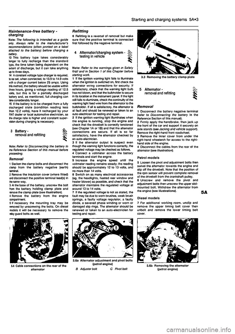
3.3 Removing the battery clamp plate
5 Alternator -removal and refitting
Removal 1 Disconnect the battery negative terminal {refer to Disconnecting the battery In the Reference Section of this manual). 2 Firmly apply the handbrake, then jack up the front of the car and support it securely on axle stands (see Jacking and vehicle support). Remove tho right-hand front roadwheel. 3 Remove Ihe Inner cover from under the right-hand wheelarch for access to tho right-hand side of the engine. 4 Disconnect the cables from the rear Of the alternator (see illustration).
Petrol models 5 Loosen the pivot and adjustment bolts then swivel the alternator towards the engine and slip off the drivebelt. Note that the position of the rpm sensor will prevent complete removal of the drivebelt from the crankshaft puiley. 6 Unscrew and remove the pivot and adjustment bolts then unscrew the upper slot-mounted bolt. Withdraw the alternator from the engine (see illustrations).
Diesel models 7 For additional working room, unclip and remove the upper timing belt cover then unbolt and remove the lower timing belt cover.
5.4 Cable connections on the rear of the alternator
5.6a Alternator adjustment and pivot bolts (petrol engine) B Adjuster bolt C Pivot bolt 5.6b Removing the alternator (petrol engine)
Page 155 of 225
Ignition system - petrol models 5B®3
Chapter 1A tor further information. Also check tnat tha accelerator cable is correctly adjusted
as
described in the relevant part of Chapter 4. If the engine is running very roughly, check the compression pressures and the valve clearances as descnbed In the relevant parts of Chapters 1 and 2. 2
H
these checks fall to reveal the cause of the problem, the vehicle should be taken to a suitably equipped Fiat dealer for testing. A wiring block connector Is Incorporated in the engine management circuit Into which a special electronic diagnostic tester can be plugged. The tester will locate the fault quickly and simply alleviating the need to test all the system components Individually which is a time consuming operation that carries a high risk of damaging the ECU. 3 The only Ignition system checks which can
oe
earned out by the home mechanic are those cescribed in Chapter 1A, relating to the spark plugs, and the ignition coll test descnbed In this Chapter. If necessary, the system wiring and wiring connectors can oe checked as descnbed in Chapter 12, Section 2, ensuring that the ECU wiring connector(s) have first
been
disconnected.
3 Ignition HT coil - ^ removal, testing and refitting
Removal 1 On 6-valve engines, unscrew the boll and remove the plastic cover from the left-hand
end
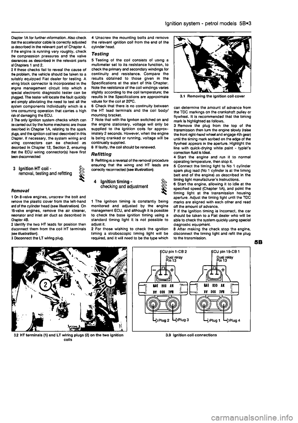
of the cylinder head (see Illustration). On 15-valve engines, remove the air cleaner, resonator and Inlet air duct as described in Chapter 4B. 2 Identify the two HT leads for position then disconnect them from the coil HT terminals jsee illustration). 3 Disconnect the LT wiring plug.
4 Unscrew the mounting bolts and remove the relevant ignition coil from the end of the cylinder head,
Testing 5 Testing of the coil consists of using a multimeter set to its resistance function, to check the primary and secondary windings for continuity and resistance. Compare the results obtained to those given In the Specifications at the start of this Chapter. Note the resistance of the coil windings varies slightly according to the coil temperature; the results In the Specifications are approximate values for the coil at 20°C. 6 Check that there is no continuity between the HT lead terminals and the coil body/ mourning bracket. 7 Note that with the ignition switched on and the engine stationary, voltage will only be supplied to the ignition cotls for approx-imately 2 seconds. However, when tho engine is being cranked or running, voltage will be continually supplied. 8 If faulty, the coil should be renewed.
Refitting 9 Refitting ts a reversal of the removal procedure ensuring that the winng and HT leads are correctly reconnected (see illustration).
4 ignition timing • checking and adjustment
1 The Ignition timing is constantly being monitored and adjusted by the engine management ECU, and although it is possible to check the base ignition liming using a standard timing light It is not possible to adjust it. 2 For those wishing to check the ignition timing a stroboscope timing light will be required, and it will need to be the type which
3.1 Removing the ignition coll cover
can determine the amount of advance from the TDC markings on the crankshaft pulley or flywheel. It Is recommended that the timing mark is highlighted as follows. 3 Remove the plug from the top of the transmission then turn tho engine slowly (raise the front right-hand wheel and engage 4th gear) until the timing mark scribed on the edge of the flywheel appears in the aperture. Highlight the line with quick-drying white paint - typist's correction fluid is ideal. 4 Start the engine and run It to normal operating temperature, then stop it. 5 Connect the timing light to No 1 cylinder spark plug lead (No 1 cylinder Is at the timing belt end of the engine) as described in the timing light manufacturer's Instructions. 6 Start the engine, allowing it to idle at the specified speed (Chapter 1A), and point the timing light at the transmission housing aperture. Adjust the timing light until the TDC marks are aligned with each other and read off the amount of advance. 7 If the ignition timing is incorrect, the car should be taken to a Fiat dealer who will be able to check the system quickly using special diagnostic equipment. 8 After making the check stop the engine, disconnect the timing light and refit the plug to the transmission.
3.2 HT terminals (1) and LT wiring plugs (2) on the two ignition colls 3.9 Ignition colt connections
Page 177 of 225
9«1
Chapter 9
Braking system
Contents
Brake disc - inspection, removal and refitting 4 Brake fluid level check See Weekly checks Brake fluid renewal See Chapter 1A or 1B Brake warning lamp check See Chapter 1A or 1B Front brake caliper - removal, overhaul and refitting 3 Front brake pad check See Chapter 1A or 1B Front brake pads - renewal 2 General information 1 Handbrake - checking and adjustment 9
Handbrake cables - removal and refitting 10 Hydraulic pipes end hoses - renewal 13 Hydraulic system - bleeding 11 Master cylinder - removal and refitting 12 Roar brake shoe check See Chapter 1A or 1B Rear brake shoes - renewal 5 Rear brake drums - removal, inspection and refitting 6 Rear wheel cylinder - removal, overhaul and refitting 7 Stop-light switch - adjustment, removal and refitting 6
Degrees of difficulty
Easy, suitable
far
novice with Sttle
experience ^
Fairly
easy,
suitable ^ (orbeginnerwith ®
some
experience
Fairly difficult, suitable
for
compe«ent ^ CHYmechanlc ^
Difficult, suitable for
experienced DIY « mechanic ^
Very difficult, ^
suitable
for
expert DIY
or professional ^
Specifications
Front disc brakes Type Disc with single-piston sliding calipers Disc diameter Petrol models with single-point Injection 240.0 mm Petrol models with multi-point Injection 257.0 mm Non-turbo diesel models 240.0 mm Turbodieselmodels 257.0 mm Disc thickness (new); Petrol models with single-point injection 10.80 to 11.10 mm Petrol models with multi-point Injection 11.80 to 12.10 mm Non-turbo diesel models 10.80 to 11.10 mm Turbodieselmodels 11.80 to 12.10 mm Minimum disc thickness (wear limit): Petrol models with single-pant Injection 9.20 mm Petrol models with multi-point Injection 10.20 mm Non-turbo diesel models 9.20 mm Turbo diesel models 10.20 mm Maximum disc runout 0.15 mm Brake pad friction material minimum thickness 1.5 mm
Rear drum brakes Drum Inner diameter (new) 180.0 to 180.25 mm Maximum drum diameter (wear limit) 181.35 mm Minimum brake shoe lining thickness 2.0 mm
Torque wrench settings Nm ibf ft
Bfeed
screw 6 4 Brake disc locating studs 12 9 Brake drum locating studs 12 9 Brake pipe and hose unions 14 10 Front caliper mounting bracket-to-hub carrier bolts 53 39 Front caliper-to-caliper bracket guide pin bolts 12 9 fleer wheel cylinder mounting boils 10 7 Roadwheel bolts 85 63
Page 178 of 225
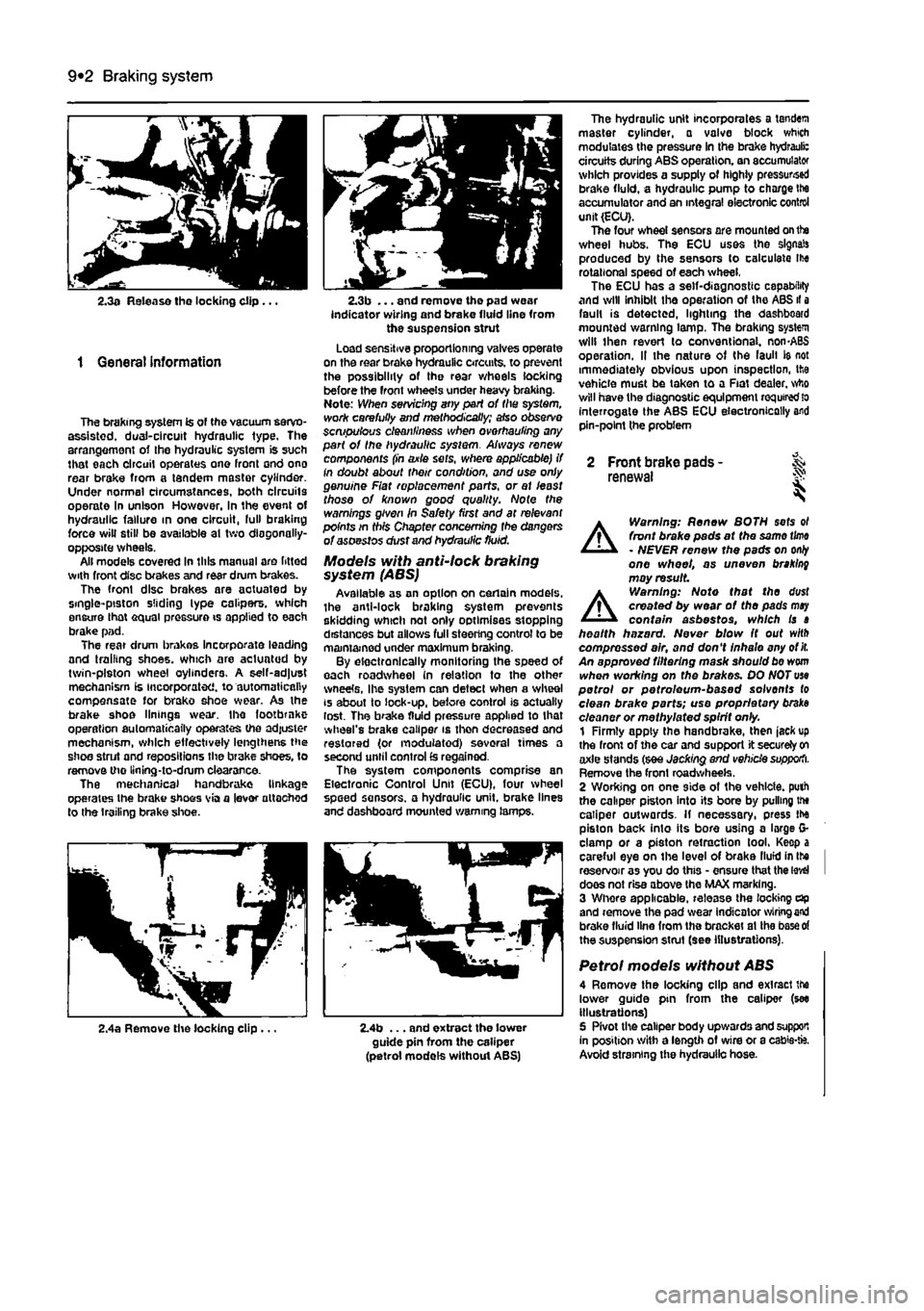
9*2 Braking system
2.3a Release tho locking clip ...
1 General information
The braking system is of the vacuum servo-assisted. dual-circuit hydraulic type. The arrangement of Ihe hydraulic system is such that each circuit operates one front ond ono rear brake from a tandem master cylinder. Under normal circumstances, both circuits operate In unison However, in the event of hydraulic failure in one circuit, lull braking force will still be available at two diagonally-opposite wheels. All models covered in this manual are fitted with front disc brakes and rear drum brakes. The front disc brakes are aotuated by single-piston sliding lype calipers, which ensure lhat equal pressure is applied to each brake pad. The rear drum brakes incorporate leading and trailing shoes, which are actuated by twin-piston wheel cylinders. A self-adjust mechanism is incorporated, to automatically compensate for brako shoe wear. As the brake shoe linings wear, the footbrnke operation automatically operates the adjuster mechanism, which effectively lengthens the shoe strut and repositions the brake shoes, to remove the llning-to-drum clearance. The mechanical handbrake linkage operates the brake shoos via a lever attached to the trailing brake shoe.
2.3b ... and remove the pad wear indicator wiring and brake fluid line from the suspension strut Load sensitive proportioning valves operate on the rear brake hydraulic circuits, to prevent the possibility of the rear wheels locking before the front wheels under heavy braking. Note: When servicing any part of the system, work carefully and methodically; also observe scmpulous cleanliness when overhauling any part of the hydraulic sysiem. Always renew components (in axle sets, where applicable) if In doubt about their condition, and use only genuine Fiat replacement parts, or at least those of known good quality. Note the warnings given in Safety first and at relevant points in this Chapter concerning fhe dangers of asoestos dust and hydraulic fluid.
Models with anti-lock braking system (ABS) Available as an option on certain models, the anti-lock braking system prevents skidding which not only optimises stopping distances but allows full steering control to be maintained under maximum braking. By electronically monitoring the speed of each roadwheel in relation to the other wneete, Ihe system can detect when a wheel is about to lock-up, before control is actually lost. The brake fluid pressure applied to that wheel's brake caliper is then decreased and restored (or modulated) several times a second until control
£s
regained. The system components comprise an Electronic Control Unit (ECU), four wheel speed sensors, a hydraulic unit, brake lines and dashboard mounted warning lamps.
The hydraulic unit incorporates a tandem master cylinder, a valve block which modulates the pressure in the brake hydrauli: circuits during ABS operation, an accumulator which provides a supply of highly pressursed brake fluid, a hydraulic pump to charge Ihe accumulator and an integral electronic control unit (ECU). The four wheel sensors are mounted on the wheel hubs. The ECU uses the signals produced by the sensors to calculate Ihe rotational speed of each wheel, The ECU has a self-diagnostic capability and will inhibit the operation of the ABS il a fault is detected, lighting the dashboard mounted warning lamp. The braking system will then revert lo conventional. non-ABS operation. II the nature of the laull ie not immediately obvious upon inspection, the vehicle must be taken to a Fiat dealer, who will have the diagnostic equipment
required
lo interrogate the ABS ECU electronically and pin-point the problem
2 Front brake pads - & renewal S
A
Warning: Renew BOTH sets ol front brake pads at the same
time
- NEVER renew the pads on
only
one wheel, as uneven braking may result
A
Warning: Note that the dust created by wear of the pads
may
contain asbestos, which is a health hazard. Never blow It out with compressed air, and don't inhale any of
it.
An approved filtering mask should be worn when working on the brakes. DO NOT use petrol or petroleum-based solvents to clean brake parts; use proprietary braks cleaner or methylated spirit only. 1 Firmly apply the handbrake, then jack up the front of the car and support it securely
on
axle stands (see Jacking and vehicle supporti. Remove the front roadwheeis. 2 Wording on one side of the vehicle, puth the caliper piston into its bore by pulling the caliper outwards. If necessary, press the piston back into its bore using a large G-clamp or a piston retraction tool. Keep a careful eye on the level of brake llufd in Ihe I reservoir as you do this - ensure that the
level
I does not rise above the MAX marking. 3 Whore applicable, release the locking dp and remove the pad wear indicator
wiring end
brake fluid line from the bracket at Ihe
base of
the suspension strut (see illustrations).
Petrol models without ABS 4 Remove the locking clip and exlracl the lower guide pin from the caliper (see illustrations) 5 Pivot the caliper body upwards and support In position with a length of wire or a cabie-fc. Avoid straining the hydraulic hose.
2,4a Remove the locking clip ... 2.4b ... and extract the lower guide pin from the caliper (petrol models without ABS)
Page 184 of 225
9*8 Braking system
6 Carefully examine the Inside of tho drum. Light scoring of the friction surface is normal, but if heavy scoring Is found, the drum must be renewed. 7 It is usual to find a lip on the dmm's inboard edge which consists of a mixture of rust and brake dust: this should be carefully scraped away, to leave a smooth surface which can be polished with fine (120 to 150-grade) emery paper. If, however, the tip is due to the friction surface being recessed by excessive wear, then the drum must be renewed. 6 If the drum Is thought to be excessively worn, or oval, its internal diameter must be measured at several points using an internal micrometer. Take measurements In pairs, the second at right-angles to the first, and compare the two, to check for signs of ovality. Provided that it does not enlarge the dium to beyond the specified maximum diameter, it may be possible to have the drum refinished by skimming or grinding; if this is not possible, Ihe drums on both sides must be renewed. Note that if the drum is to be skimmed, BOTH drums must be refinished. to maintain a consistent Internal diameter on both sides.
Refitting 9 II a new brake drum is to be Installed, use a suitable solvent to remove any preservative coating thai may have been applied to its internal fnction surfaces. Note that it may also be necessary to shorten the adjuster strut length, by rotating the sedated strut wheel, lo allow Ihe drum lo poss over the brake shoes • see Section S for details. 10 II tho original dfum is being refitted, align the marks made on the drum and hub before removal, then lit the drum over the hub. Refit the locating studs and tighten them to the specified torque. 11 Depress the footbrake repeatedly to expand the brake shoes against the drum, and ensure that normal pedal pressure Is restored. 12 Check and if necessary adjust the handbrake cable as described In Section 9. 13 Refit tho roadwheels, and lower the vehicle to the ground.
7 Rear wheel cylinder -removal, overhaul and refitting jS
A
Warning: Before starting work, refer to the warnings at tho beginning of Sections 2 and 11 concerning the dangers ot handling asbestos dust and hydraulic fluid.
Removal 1 Remove the brake drum fsee Section 6). 2 Remove the brake shoes (see Section 5). 3 To minimise fluid loss during the following operations, remove the master cylinder reservoir cap. then tighten it down onto a piece of polythene, lo obtain an airtight seal.
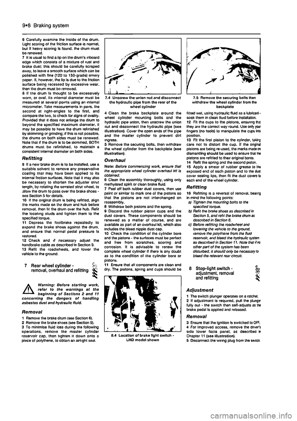
the hydraulic pipe from the rear of the wheel cylinder 4 Clean the brake backplate around Ihe wheel cylinder mounting boits and the hydraulic pipe union, then unscrew the union nut and disconnect Ihe hydraulic pipe (see illustration). Cover the open ends of the pipe and the master cylinder to prevent dirt ingress, 5 Remove the securing bolts, then withdraw the wheel cylinder from the backplate (soe Illustration).
Overhaul Note: Before commencing woric, ensure that the appropriate wheel cylinder overhaul kit is obtained. 6 Clean tho assembly thoroughly, using only methylated spirit or clean brake fluid, 7 Peel off both rubber dust covers, then use paint or similar to mark one ot the pistons so that the pistons are not interchanged on reassembly. 8 Withdraw both pistons and tho spring. 9 Discard the rubber piston cups and the dust covers. These components should be renewed as a matter of course, and are available 3s part of an overhaul kit, which also Includes the bleed nipple dust cap. 10 Check the condition of the cylinder bore and the pistons - the surfaces must be perfect and free from scratches, scoring and corrosion, It is advisable to renew the complete wheel cylinder if there is any doubt as to the condition ot the cylinder bore or pistons. 11 Ensure thai all components are clean and dry. The pistons, spring and cups should be
8.4 Location of brake tight switch-LHD model shown
withdraw the wheel cylinder from the backplate fitted wet, using hydraulic fluid as a lubricant • soak them in clean fluid before installation. 12 Fit the cups to the pistons, ensuring that they are the correct way round. Use only your fingers (no tools) to manipulate the cups into position. 13 Fit the first piston to the cylinder, taking care not to distort the cup. If the original pistons are being re-used, ihe marks
made on
dismantling should be used to ensure that the pistons are refitted to their original bores, 14 Refit the spring and the second pfston. 15 Apply a smear of rubber grease to Ihe exposed end of each piston and to the dust cover sealing lips, then fit Ihe dust covers to each end of the wheel cylinder.
Refitting 16 Refitting is a reversal of removal, bearirg in mind the following points: a) Tighten the mounting bolts to the specified torque. b) Refit the brake shoes as desenbod
In
Section 5. and refit the brake drum
as
described in Section 6. c) Before refitting the roadwheel
and
lowering the vehicle to the ground, remove the polythene from the fluid reservoir, and bleed the hydraulic
system
as described in Section f
1.
Note that if
nc
other part of the system has been disturbed, it should only bo necessary
to
bleed the relevant rear circuit.
8 Stop-light switch • & adjustment, removal J? and refitting
Adjustment 1 The switch plunger operates on a ratchet 2 If adjustment Is required, pull the plunge fully out - (he 9witch then sell-adjusts as the brake pedal Is applied and released.
Removal 3 Ensure that the ignition Is switched to OfF. 4 For Improved access, remove the driver's side lower facia panel, as described in Chapter 11 (see Illustration). 5 Disconnect the wiring plug from the switch.
Page 186 of 225
9*10 Braking system
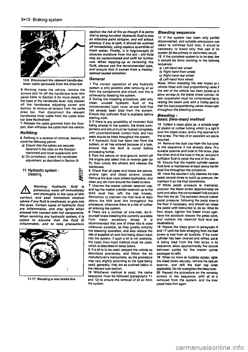
10.6 Disconnect the relevant handbrake inner cable (arrowed) from the draw bar 6 Working inside ihe vehicle, remove Ihe screws and lift off the handbrake lever trim panel (refer to Section 9 for more detail). At the base of the handbrake lever, full/ slacken off the handbrake adjusting screw and locknut, to remove oil tension from the cable draw bar, then disconnect the relevant handbrake inner cable from the cable draw bar (see illustration) 7 Release the cable grommet from tho floor-pan, then withdraw the cable from the vehicle.
Refitting 8 Refitting Is a reversal of removal, bearing in mind the following points: a) Ensure that the cables are securely fastened In the clips on the floorpan beetshield and lower suspension a/m. b) On completion, check the handbrake adiustment, as described in Section 9.
11 Hydraulic system -bleeding
A
Warning: Hydraulic fluid is poisonous; wash off immediately and thoroughly In the case ot skin contact, and seek immediate medical advice if any fluid is swallowed, or gets into the eyes. Certain types of hydraulic fluid are Inflammable, and may ignite when allowed into contact with hot components. When servicing any hydraulic system, it Is safest to assume that the fluid IS inflammable, and to take precautions
11.17 Bleeding a rear brake line
against the risk of fire as though it is petrol that Is being handled. Hydraulic fluid is also an effective paint stripper, and will attack plastics; If any is spilt, It should be washed off immediately, using copious quantities of fresh water. Finally, it Is hygroscopic (it absorbs moisture from the air) • old fluid may be contaminated and unfit tor further use. Whan topping-up or renewing the fluid, always use the recommended type, and ensure that It comes from a freshly-opened sealed container.
General 1 The correct operation of any hydraulic system is only possible after removing all air from the components and circuit; and this Is achieved by bleeding the syslem. 2 During the bleeding procedure, add only clean, unused hydraulic fluid of the recommended type; never re-use fluid that has already been bled from the system. Ensure that sufficient fluid is available before starting work. 3 If there is any possibility of incorrect fluid being already in the system, the brake com-ponents and circuit must be Flushed completely with uncontamlnated, correct fluid, and new seals should be fitted throughout the system. 4 If hydraulic fluid has been lost from the system, or air has ontered because of a leak, ensure that the fault is cured before proceeding further. 5 Park Ihe vehicle on level ground, switch off the engine and select first or reverse gear (or P), then chock the wheels and release the handbrake. 6 Cheek that all pipes and hoses are secure, unions tight and bleed screws closed. Remove Ihe dust caps (whore applicable), and clean any dirt from around the bleed screws. 7 Unscrew the master cylinder reservoir cap, and top Ihe master cylinder reservoir up to the MAX level line; refit the cap loosely. Rememoer to maintain the fluid level at least above the MIN level line throughout the procedure, otherwise there is a risk of further air entering the syslem. 8 There are a number of one-man. do-It-yourself brake bleeding kits currently available from motor accessory shops. It is recommended that one of these kits is used whenever possible, as they greatly simplify the bleeding operation, and also reduce the risk of expelled air and fluid being drawn back into the system. If such a kit is not available, the basic (two-man) method must be used, which is described in detail below. 9 If a kit Is to be used, prepare the vehicle as described previously, and follow the kit manufacturer's instructions, as Ihe procedure may vary slightly according to the type being used; generally, they are as outlined below in the relevant sub-section. 10 Whichever method is used, the same sequence must be followed (paragraphs 11 and 12) to ensure Ihe removal of all air from the system.
Bleeding sequence 11 If Ihe system has been only
partial!?
disconnected, and suitable precautions wwe taken to minimise fluid loss, it should be necessary to bteod only that part of the system (le the primary or secondary circuit). 12 If the complete system Is to be bled, then It should be done working in the following sequence: a) Left-hand rear wheel b) Right-hand front wheel. c) Right-hand rear wheel. d) Left-hand front wheel. Note: When bleeding the rear brakes
on a
vehicle ritled with load proportioning valves: i the rear of the vehicle has been jacked
up to
allow access to ihe brake wheel cylinder,
tha
rear suspension must be compressed
(eg
raising the beam axle with a trolley
jack) so
that the load proportioning valves
remain open
throughout the bleeding process.
Bleeding -basic (two~man) method 13 Collect a clean glass jar, a suitable length of plastic or rubber tubing which Is a light fit over the bleed screw, end a ring spanner lo
Rt
the screw. The help of an assistant will also tie required. 14 Remove the dust cap from the first screw In the sequence if not already done. Fit a suitable spanner and tube to the screw, place the other end of Ihe tube In the jar. and
pour in
sufficient fluid to cover the end of the tube. 15 Ensure that the master cylinder reservoir fluid level is maintained at least above the
MIN
level line throughout the procedure. 16 Have the assistant fully depress the brefce pedal several times to build up pressure, then maintain it on the final downstroke. 17 While pedal pressure is maintained, unscrew ihe bleed screw (approximately one turn) and allow the compressed fluid and orto flow into the
Jar,
The assistant should maintah pedal pressure, following the pedal down to the floor if necessary, and should not rrtaase Ihe pedal until instructed to do so. When ihe flow stops, tighten the bleed screw again, have the assistant retease the pedal sfowty, and recheck the reservoir fluid level (see Illustration). 18 Repeat Ihe steps given in paragraphs 16 end 17 until the fluid emerging from the bled screw is free from air bubbles. If Ihe master cylinder has been drained and refilled,
and
at Is being bled from the first screw In the sequence, allow approximately five seconds between cycles for the master cylinder passages to refill. 19 When no more air bubbles appear, tighter, the bleed screw securely, remove Ihe tube arc spanner, and refit the dust cap (where applicable). Do not overtighten the bleed sew. 20 Repeat the procedure on tho remaining screws In the sequence, until ail air is removed from the system, and the brake pedal feels firm again.
Page 203 of 225
11 *2 Bodywork and fittings
on vehicles with wax-based underbody protective coating, or the coating will be removed. Such vehicles should be inspected annually, preferably just prior lo Winter, when the underbody should be washed down, and any damage to the wax coating repaired. Ideally, a completely fresh coat should be applied. It would also be worth considering the use of such wax-based protection for injection into door panels, sills, box sections, etc, as an additional safeguard against rust damage, where such protection Is not provided by the vehicle manufacturer. After washing paintwork, wipe off with a chamois feather to give an unspotted clear finish. A coat of clear protective wax polish wilt give added protection against chemical pollutants in the air. If the paintwork sheen has duiled or oxidised, use a cleaner/polisher combination to restore the brilliance of the shine. This requires a little effort, but such dulling Is usually caused because regular washing has been neglected. Care needs to be taken with metallic paintwork, as special non-abrasive cleaner/polisher is required to avoid damage to the finish, Always check that the door and ventilator opening drain holes and pipes are completely clear, so that water can be drained out. Brightwork should be treated In the same way as paintwork. Windscreens and windows can be kept clear of the smeary film which often appears, by the use of proprietary glass cleaner. Nover use any form of wax or other body or chromium polish on glass.
Maintenance -upholstery and carpets
Mats and carpets should be brushed or vacuum-cleaned regularly, to keep them free of grit. If they are badly stained, remove them from the vehicle for scrubbing or sponging, and make quite sure they are dry before refitting. Seats and interior trim panels can be kept clean by wiping with a damp cloth. If they do become stained (which can be more apparent on light-coloured upholstery), use a little liquid detergent and a soft nail brush lo scour the grime out of the grain of the material. Do not forget to keep the headlining clean in the same way as the upholstery. When using liquid cleaners inside the vehicle, do not over-wet the surfaces being cleaned. Excessive damp could get Into the seams and padded interior, causing stains, offensive odours or even rot.
If the Inside of the vehicle gets wet accidentally, tt Is worthwhile taking some trouble to dry ft out property, particularly where carpets an involved. Do not leave oil or electric heaters inside the vehicle for this purpose.
4 Minor body damage -repair
Repairs of minor scratches In bodywork If the scratch Is very superficial, and does not penetrate to the metal of the bodywork, repair is very simple. Lightly rub the area of the scratch with a paintwork renovator, or a very fine cutting paste, to remove loose paint from the scratch, and to clear the surrounding bodywork of wax polish, Rinse the area with clean water. Apply touch-up paint to ihe scratch using a fine paint brush; continue to apply fine layers of paint until the surface of the paint In the scratch Is level with the surrounding paintwork. Allow Ihe new paint at least two weeks to harden, then blend it Into the surrounding paintwork by rubbing the scratch area with a paintwork renovator or a very fine cutting paste. Finally, apply wax polish. Where the scratch has penetrated right through to the metal of the bodywork, causing the metal to rust, a different repair technique Is required. Remove any loose rust from the bottom of the scratch with a penknife, then apply rust-inhibiting paint to prevent the formation of rust in the future. Using a rubber or nylon applicator, fill the scratch with bodystopper paste. If required, this paste can be mixed with cellulose thinners to provide a very thin paste which is ideal for filling narrow scratches. Before the stopper-paste in Ihe scratch hardens, wrap a piece of smooth cotton rag around the top of a finger. Dip the finger in cellulose thinners, and quickly sweep it across the surface of the stopper-paste in the scratch: this will ensure that the surface of the stopper-paste is slightly hollowed. The scratch can now be painted over as described earlier In this Section.
Repairs of dents in bodywork When deop denting of the vehicle's bodywork has taken place, the first task is to put) the dent out. until the affected bodywork almost attains rts onginal shape. There is little polnl in trying to restore Ihe original shape completely, as the metal in the damaged area will have stretched on impact, and cannot be reshaped fully to its original contour. It Is better to bring the level of the dent up to a point which is about 3 mm below the level of the surrounding bodywork. In cases where Ihe dent is very shallow anyway, It is not worth trying to pull it out at all. If the underside of the dent is accessible, it can be hammered out gently from behind, using a mallet with a wooden or plastic head, Whilst doing this, hold a suitable block of wood firmly against (he outside of Ihe panel, to absorb the impact from the hammer blows and thus prevent a large area of the bodywork from being 'belled-out".
Should the dent be In a section of (I* bodywork which has a double skin, or seme other factor making It Inaccessible from behind, a different technique is called for. Dull several small holes through the metal inside Ihe area - particularly in the deeper section. Then screw long self-tapping screws Into the holes, just sufficiently for them to gain a good purchase in the metal. Now the dent can be pulled out by pulling on the protruding heads of the screws with a pair of pliers. The next stage of the repair Is the removal of the paint from the damaged area, and from an inch or so of the surrounding 'sound' bodywork. This is accomplished most easily by using a wire brush or abrasive pad on a posver drill, although it can be done just as effectively by hand, using sheets of abrasive paper. To complete the preparation for filling, score the surface of the bare metal wflhi screwdriver or the tang of 8 file, or alternatively, drill small holes In the affected area. This will provide a really good 'key' for the filler paste. To complete the repair, see the Section on filling and respraying.
Repairs of rust holes or gashes in bodywork Remove all paint from the affected area, and from an inch or so of the surrounding 'sound' bodywork, using an abrasive pad
or a
wire brush on a power drill. If these are not available, a few sheets of abrasive paper wil do the job most effectively. With the paint removed, you will be able to judge the severity of the corrosion, and therefore decide whether to renew the whole panel (if this is possible) or to repair the affected area. New body panels are not as expansive as most people think, and it is often quicker and more satisfactory to fit a new panel than to attempt to repair large areas of corrosion. Remove all fittings from Ihe affected area, except those which will act as a guide to ttie original shape of the damaged bodywork (eg headlight shells etc). Then, using tin snips
or a
hacksaw blade, remove all loose metal snd any other metal badly affected by corrosion. Hammer the edges of the hole inwards, in order to create a slight depression for the filer paste. Wire-brush the affected area to remove tha powdery rust from the surface of the remaining metal. Paint Ihe affected area with rust-inhibiting paint, if the beck of the rusted area is accessible, treat this also. Before filling can take place, ft will be necessary to block the hole in some
way.
TNs can be achieved by the use of aluminium cr plastic mesh, or aluminium tape. Aluminium or plastic mesh, or glass-fibre matting, is probably the best material to use for a large hole. Cut a piece to tha approximate size and shape of tho hole to b« filled, then position it In the hole so that its edges are below the level of the surrounding bodywork. It can be retained in position by
Page 204 of 225
Bodywork and fittings
11
*3
several blobs of filler paste around its periphery. Aluminium tape should be used for small or very narrow holes. Pull a piece off the roll, trim it to the approximate size and shape required, then pull off the backing paper (if used) and stick the tape over the hole; it can be overlapped if the thickness of one piece is Insufficient. Burnish down the edges of the tape with the handle of a screwdriver or similar, to ensure that the tape is securely attached to the metal underneath.
Bodywork repairs -filling and respraying Before using this Section, see the Sections on dent, deep scratch, rust holes and gash repairs. Many types of bodyfiller are available, but generally speaking, those proprietary kits which contain a tin of filler paste and a tube of resin hardener are best for this type of repair. A wide, flexible plastic or nylon applicator will be found invaluable for imparting a smooth and well-contoured finish to the surface of the filler. Mix up a little filler on a clean piece of card or board • measure the hardener carefully (follow the maker's instructions on the pack), otherwise the filler will set too rapidly or too slowly. U3ing the applicator, apply the filler paste to the prepared area; draw the applicator across the surface of the filler to achieve the correct contour and to level the surface. As soon as a contour that approximates to the correct one is achieved, stop working the paste - if you carry on too long, the paste will become sticky and begin lo 'pick-up' on the applicator. Continue to add thin layers of filler paste at 20-minute Intervals, until the level of the filler is just proud of the surrounding bodywork. Once the filler has hardened, the excess can be removed using a metal plane or file. From then on, progressively-finer grades of abrasive paper should be used, starting with a 40-grade production paper, and finishing with a 400-grade wet-and-dry paper. Always wrap the abrasive paper around a flat rubber, cork, or wooden block • otherwise the surface of the filler will not be completely flat. During the smoothing of the filler surface, the wet-and-dry paper should be periodically rinsed in water. This will ensure that a very smooth finish is imparled to the filler at the final stage. At this stage, the dent should be surrounded by a ring of bare metal, which in turn should be encircled by the finely feathered' edge of the good paintwork. Rinse the repair area with clean water, until all of the dust produced by the rubbing-down operation has gone. Spray the whole area with a light coat of primer - this will show up any imperfections In the surface of the filler. Repair these imperfections with fresh filler paste or bodystopper, and once more smooth the surface with abrasive paper. Repeat this
spray-and-repair procedure until you are satisfied that the surface of the filler, and the feathered edge of the paintwork, are perfect. Clean the repair area with clean water, and allow to dry fully.
flflfl^gl tf txxfystopper is used, it can WiMiiBi be mixed with cellulose Hi NT thinners to form a really thin 1 1 paste which is Ideal for filling small holes.
The repair area Is now ready for final spraying. Paint spraying must be carried out in a warm, dry, windless and dust-free atmosphere. This condition can be created artificially if you have access to a large indoor working area, but If you are forced to work in the open, you will have to pick your day very carefully. If you are working indoors, dousing the floor In the work area with water will help to settle the dust which would otherwise be in the atmosphere. If the repair area is confined to one body panel, mask off the surrounding panels; this will help to minimise the effects of a slight mis-match in paint colours. Bodywork fittings (eg chrome strips, door handles etc) will also need to be masked off. Use genuine masking tape, and several thicknesses of newspaper, for the masking operations. Before commencing to spray, agitate the aerosol can thoroughly, then spray a test area (an old tin. or similar) until the technique is mastered. Cover the repair area with a thick coat of primer; the thickness should be built up using several thin layers of paint, rather than one thick one. Using 400-grade wet-and-dry paper, rub down the surface of the pnmer until it is really smooth. While doing this, the work area should be thoroughly doused with water, and the wet-and-dry paper periodically rinsed in water. Allow to dry before spraying on more paint. Spray on the top coat, again building up the thickness by using several thin layers of paint. Start spraying at one edge of the repair area, and then, using a side-to-side motion, work until the whole repair area and about 2 inches of the surrounding original paintwork is covered. Remove all masking material 10 to 15 minutes after spraying on the final coat of paint. Allow the new paint at least two weeks to harden, then, using a paintwork renovator, or a very fine cutting paste, blend the edges of the paint into the existing paintwork. Finally, apply wax polish.
Plastic components With the use of more and more plastic body components by the vehicle manufacturers (eg bumpers, spoilers, and in some cases major body panels), rectification of more serious damage to such items has become a matter of either entrusting repair work to a specialist in this field, or renewing complete components. Repair of such damage by the
DIY owner is not really feasible, owing to the cost of the equipment and materials required for effecting such repairs. The basic technique involves making a groove along the line of the crack in the plastic, using a rotary burr In a power drill. The damaged part is then welded back together, using a hot-air gun to heat up and fuse a plastic filler rod Into the groove. Any excess plastic is then removed, and the area rubbed down to a smooth finish. It is important that a filler rod of the correct plastic is used, as body components can be made of a variety of different types (eg polycarbonate, ABS, polypropylene). Damage of a less senous nature (abrasions, minor cracks etc) can be repaired by the DIY owner using a two-part epoxy filler repair material. Once mixed in equal proportions, this is used in similar fashion to the bodywork filler used on metal panels. The filler is usually cured in twenty to thirty minutes, ready for sanding and painting. If the owner is renewing a complete component himself, or If he has repaired it with epoxy filler, he will be left with the problem of finding a suitable paint for finishing which is compatible with the type of plastic used. At one time, the use of a universal paint was not possible, owing to the complex range of plastics encountered In body component applications. Standard paints, generally speaking, will not bond to plastic or rubber satisfactorily. However, it is now possible to obtain a plastic body parts finishing kit which consists of a pre-pnmer treatment, a primer and coloured top coat. Full Instructions are normally supplied with a kit, but basically, the method of use is to first apply the pre-pnmer to the component concerned, and allow It to dry for up to 30 minutes. Then the primer is applied, and left to dry for about an hour before finally applying the special-coloured top coat. The result is a correctly-coloured component, where the paint will flex with the plastic or rubber, a property that standard paint does not normally possess.
5 Major body damage -repair
Where serious damage has occurred, or large areas need renewal due to neglect, it means that complete new panels will need welding-in, and this is best left to professionals. If the damage is due to Impact, it will also be necessary to check completely the alignment of the bodyshell, and this can only be carried out accurately by a Fiat dealer using special jigs. If the alignment of the bodyshell is not corrected, the car's handling may be seriously affected. In addition, excessive stress may be Imposed on the steering, suspension, tyres or transmission, causing abnormal wear or even complete failure.
Page 214 of 225
10*1
Chapter 12
Body electrical systems
Contents
Bulbs (exterior lights) - renewal 4 Bulbs (interior lights) - renewal 5 Electrical fault finding - general information 2 Exterior light units - removal and refitting 6 Fuses and relays - general Information 3 General information and precautions 1 Headlight beam alignment • general Information 6 Horn • removal and refitting 9 Instrument panel - removal and refitting 7 Loudspeakers - removal and refitting 10
Degrees of difficulty
Radio aerial - removal and refitting 11 Radio/cassette player • removal and refitting 12 Speedometer drive cable - removal and refitting 13 Switches - removal end refitting 14 Tailgate wiper motor - removal and refitting 15 Windscreen wiper motor - removal and refitting 17 Windscreen/tailgate washer system components • removal and refitting 16 Wiper arm • removal and refitting 18
Easy,
statable for ^
novice with liffle
|| experience ^
Fairly
easy,
suitable for beginner with ^ some experience ^
Fabtycffficiit,
suitable
for competent ^
DIY
mechanic ^
Difficult, suitable for
^ experienced DIY JR mechanic
Very difficult,
A,
suitable
for
expert DIY
Sj or professional ^
Specifications
Bulb ratings Watts Headlights 60/55 Front long range driving light 55 Front fogllght 55 Front direction Indicator light 21 Front sidelight 5 Front direction indicator repeater light 5 Stop light 21 Tall light 5 Rear direction indicator light 21 Reversing light 21 near fogllght 21 Hear number plate light 5 Courtesy light 10 Map reading light 5
1 Genera! information and precautions
A
Warning: fie/Ore carrying out any work on the electrical system, read through the precautions given in Safety first! at the beginning of this manual, and in Chapter 8. The electrical system is of 12-volt negative earth type. Power for the lights and all electrical accessories is supplied by a lead/acid type battery, which is charged by the alternator. This Chapter covers repair and service procedures for the various electrical components not associated with the engine. Information on the battery, alternator and starter motor can be found in Chapter 5. It should be noted that, prior to working on any component In the electrical system, the
battery negative terminal should first be disconnected, to prevent the possibility of electrical short-circuits and/or fires. Caution: Before proceeding, refer to Disconnecting the battery In the Reference Section of this manual for further information.
2 Electrical fault finding-general information
Note: Refer to the precautions given In Safety first! and in Section 1 of this Chapter before starting work. The following tests relate to testing ot the main electrical circuits, and should not be used to test delicate electronic circuits (such as antHock braking systems), particularly where an electronic con fro/ module is used.
General 1 A typical electrical circuit consists of an electrical component, any switches, relays, motors, fuses, fusible links or circuit breakers related to that component, and the wiring and connectors which link the component to both the battery and the chassis. To help to pinpoint a problem in an electrical circuit, wiring diagrams are Included at the end of this manual. 2 Before attempting to diagnose an electrical fault, first study the appropriate wiring diagram, to obtain a more complete understanding of the components included In the particular circuit concerned. The possible sources of a fault can be narrowed down by noting whether other components related to the circuit are operating properly. If several components or circuits fait at one time, the problem Is likely to be related to a shared fuse or earth connection.