Cylinder head tightening FIAT PUNTO 1996 176 / 1.G Workshop Manual
[x] Cancel search | Manufacturer: FIAT, Model Year: 1996, Model line: PUNTO, Model: FIAT PUNTO 1996 176 / 1.GPages: 225, PDF Size: 18.54 MB
Page 57 of 225
2A*10 SOHC (8-valve) petrol engine in-car repair procedures
Preparation for refitting 16 The mating faces of the cylinder head and cylinder block must be perfectly clean before
refitting
the head. Use a hard plastic or wooden scraper to remove all traces of gasket and carbon; also clean the piston crowns. Take padicular care when cleaning the piston crowns as the soft aluminium alloy is easily damaged. Make sure that the carbon is not afowed to enter the oil and water passages -Ihs is particularly important for the lubrication
system, as
carbon could block the oil supply to
Ihe
engine's components. Using adhesive tape
and
paper, seal the water, oil and bolt holes in tf« cylinder block. To prevent carbon entering twgap between the pistons and bores, smear
a
iittte grease in the gap. After cleaning each piston, use a small brush to remove all traces of grease and carbon from the gap, then wipe away the remainder with a clean rag. Clean all
ttie pistons
in the same way. 17 Check the mating surfaces of the cylinder block and the cylinder head for nicks, deep scratches and other damage. If slight, they may be removed carefully with a file, but if (xcassive, machining may be the only alternative to renewal. If warpage of the Cytodar head gasket surface is suspected, use a straight-edge to check it for distortion.
Refer
to Part 0 of this Chapter if necessary. 18 Check the condition of the cylinder head
MRS.
and particularly their threads, whenever
they are
removed. Wash the bolts In a suitable solvent, and wipe them dry. Check each bolt for any sign of visible wear or damage, renewing them if necessary.
Refitting 18 Before refitting Ihe assembled cylinder head, make sure that the head and block mating surfaces are perfectly clean, and that
the
bolt holes in the cylinder block have been
mopped
out to clear any oil. 20 Check that the camshaft and crankshaft sprocket timing marks are still aligned with tteir respective cylinder head and oil pump covtr marks as described in Section 2. 21 The new gasket should not be removed from its nylon cover until required for use. Fit
the
gasket dry, and make sure that the mating surfaces on the head and block are perfectly dean.
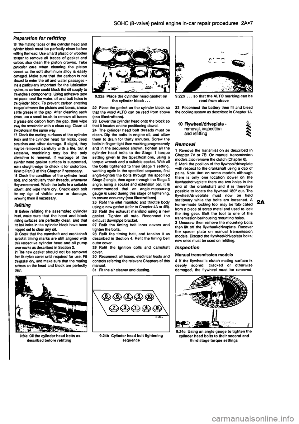
9.22a Place the cylinder head gasket on the cylinder block ... 22 Place the gasket on the cylinder block so that the word ALTO can be read from above (see illustrations). 23 Lower the cylinder head onto the block so that It locates on the positioning dowel. 24 The cylinder head bolt threads must be clean. Dip the bolts In engine oil. and allow them to drain for thirty minutes. Screw the bolls in finger-tight then working progressively and in the sequence shown, tighten all the cylinder head bolts to the Stage 1 torque setting given In the Specifications, using a torque wrench and a suitable socket. With all the bolts tightened to their Stage 1 setting, working again in the specified sequence, first angle-tighten the bolts through ihe specified Stage 2 angle, then again through the Stage 3 angle, using a socket and extension bar. It is recommended that an angle-measuring gauge is used dunng this stage of tightening, to ensure accuracy (see Illustrations). 25 Refit the inlet manifold and throttle body using a new gasket (refer to Chapter 4A or 4B). 28 Refit the exhaust manifold using a new gasket. Tighten all nuts. Reconnect the exhaust downplpe bracket. 27 Refit the timing belt inner covers and tighten the bolls. 28 Refit the timing belt, and tension It as described in Section 4. Refit the timing belt outer cover. 29 Refit the ignition colls and camshaft cover. 30 Reconnect all hoses, electrical leads and controls referring the relevant Chapters of this manual. 31 Fit the air cleaner and ducting.
9.22b ... so that the ALTO marking can be read from above 32 Reconnect the battery then fill and bleed the cooling system as described in Chapter 1A.
10 Flywheel/driveplate • ^ removal, inspection
and
refitting ^
Removal 1 Remove the transmission as described in Chapter 7A or 7B. On manual transmission models also remove the clutch (Chapter 6). 2 Mark the position of the flywheel/driveplate with respect to the crankshaft using a dab of paint. Note thai on some models although there is only one location dowel on the flywheel/driveplate there are two holes in the eno of the crankshaft and it is therefore possible to locate Ihe flywheel 180n out. The flywheel/driveplate must now be held stationary while the bolts are loosened. A home-made locking tool may be fabricated from a piece of scrap metal and used to lock the ring gear. Bolt the tool to one of the transmission bellhousing mounting holes. 3 Unscrew then remove the mounting bolts then lift off the flywheel/driveplate. Recover the spacer plate on manual transmission models. Discard the fiywheet/drivepiate boils; new ones must be used on refitting.
Inspection
Manual transmission models 4 If the flywheel's clutch mating surface is deeply scored, cracked or otherwise damaged, the flywheel must be renewed.
JEaMKA. mar 9.24c Using an angle gauge to tighten the cylinder head bolts to their second and third stage torque settings
L
Page 67 of 225
2B*7 DOHC (16-valve) petrol engine in-car repair procedures
35 Slacken the tensioner pulley retaining nut and reposition the tensioner to align the
mobile
indicator with the fixed reference mark
on the
pulley face (see illustration). Hold the
pdley in
this position and tighten the retaining
nut to the
specified torque. 36 Turn the crankshaft through a further two complete turns In the normal direction of rotation. Check that the timing is correct by alining Ihe piston positioning tools and
camshaft
locking tools as described previously. 37 When all is correct, remove the setting rri
locking
tools and refit the sealing plugs to 1ft© cylinder head extension, using new 0-
nr^s if
necessary. Tighten the plugs securely. 38 Refit the spark plugs as described in Chapter 1A. 39 Refit Ihe ECU and secure with Ihe mooning bolts. 40
Renew the
injector O-ring seals, smear them Kith
8 little
Vaseline then locate the injectors and tef rail onto the inlet manifold lower section.
Saute Ihe fuel rail
with the two retaining bolts. 41 Relit the inlet manifold upper section using new sealing O-rlngs If necessary and
sectre
with the two bolts. 42 Reconnect the wiring connectors for the tot injector harness and the intake air temp-erature/pressure sensor, then connect the fuel pressure regulator vacuum hose and tha
EVAP
purge valve hose. 43 Reconnect the wiring connectors for the ihrottls potentiometer, idle control stepper motor and coolant temperature sensor. Reconnect the brake servo vacuum hose. 44 Refit and adjust the accelerator cable as described in Chapter 4B. 46 Refit the upper and lower timing belt
covers
together with the TDC sensor wiring. 46 Refit the crankshaft pulley and tighten the
three
retaining bolts securely. 47 Refit the air cleaner. Inlet air duct and resonator as described in Chapter 4B. 48
Refit
tha auxiliary drivebelt(s) as described i/t Chapter 1A, then reconnect the battery
S Timing belt tensioner
and
sprockets -
removal
and refitting
Timing
belt tensioner
Removal I
Remove
the timing belt as described in
Section
4. 1 Completely unscrew the tensioner nut and Wiethe tensioner off the mounting stud-Inspection
3 Wipe
the tensioner clean but do not use Kfrents that may contaminate the bearings.
Spin
the tensioner pulley on its hub by hand.
Sfcfl
movement or excessive freeplay is an rcfceticn of severe wear: the tensioner is not 3 serviceable component, and should be nnewsd.
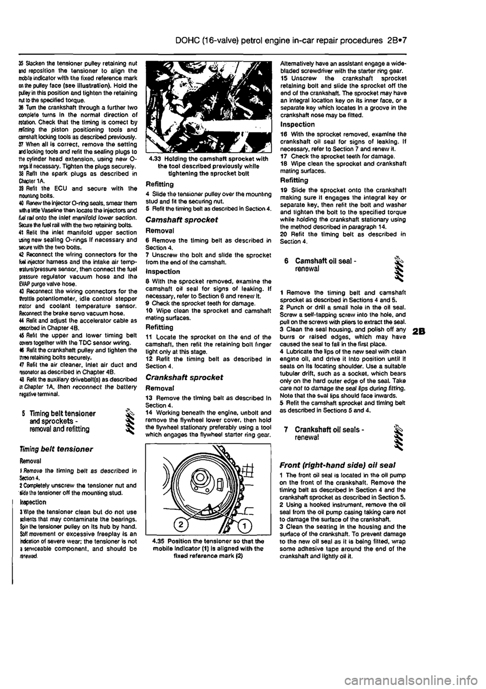
4.33 Holding the camshaft sprocket with the tool described previously while tightening the sprocket bolt Refitting 4 Slide the tensioner pulley over the mounting stud and fit the securing nut. 5 Refit the timing belt as described in Section 4. Camshaft sprocket Removal 6 Remove the timing belt as described in Section 4. 7 Unscrew the bolt and slide the sprocket from the end of the camshaft. Inspection 8 With the sprocket removed, examine the camshaft oil seal for signs of leaking. If necessary, refer to Section 6 and renew it. 9 Check the sprocket teeth for damage. 10 Wipe clean the sprocket and camshaft mating surfaces. Refitting 11 Locate the sprocket on the end of the camshaft, then refit the retaining boll finger tight only at this stage. 12 Refit the timing belt as described in Section 4.
Crankshaft sprocket Removal 13 Remove the timing bell as described In Section 4. 14 Working beneath the engine, unbolt and remove the flywheel lower cover, then hold the flywheel stationary preferably using a tool which engages the flywheel starter ring
<
Alternatively have an assistant engage a wide-bladed screwdriver with the starter ring gear. 15 Unscrew the crankshaft sprocket retaining bolt and slide the sprocket off the end of the crankshaft. The sprocket may have an integral location key on its inner face, or a separate key which locates In a groove in the crankshaft nose may be fitted. Inspection 16 With the sprocket removed, examine the crankshaft oil seal for signs of leaking. If necessary, refer to Section 7 and renew it. 17 Check the sprocket teeth for damage. 18 Wipe clean the sprocket and crankshaft mating surfaces. Refitting 19 Slide the sprocket onto the crankshaft making sure
11
engages the integral key or separate key, then refit the bolt and washer and tighten the bolt to the specified torque while holding the crankshaft stationary using the method described in paragraph 14. 20 Refit the timing belt as described in Section 4.
6 Camshaft
oil
seal -renewal
1 Remove the timing belt and camshaft sprocket as described in Sections 4 and 5. 2 Punch or drill a small hole in the oil seal. Screw a self-tapping screw into the hole, and pull on the screws with pliers to extract the seal. 3 Clean the seal housing, and polish off any burrs or raised edges, which may have caused the seal to fall in the first place. 4 Lubricate the lips of the new seal with clean engine oil, and drive it into position until It seats on its locating shoulder. Use a suitable tubular drift, such as a socket, which bears only on the hard outer edge of the seal. Take care nof to damage the seal lips during fitting. Note that the Seal lips should face inwards. 5 Refit the camshaft sprocket and timing belt as described in Sections 5 and 4.
7 Crankshaft oil seats -renewal I
4.35 Position the tensioner so that the mobile Indicator (1) is aligned with the fixed reference mark (2)
Front (right-hand side) oil seal 1 The front oil seal is located in the oil pump on the front of the crankshaft. Remove the timing belt as described in Section 4 and the crankshaft sprocket as described in Section 5. 2 Using a hooked Instrument, remove the oil seal from the oil pump casing taking care not to damage the surface of the crankshaft. 3 Clean the seating in the housing and the surface of the crankshaft. To prevent damage to the new oil seal as it is being fitted, wrap some adhesive tape around the end of the crankshaft and lightly oil it.
Page 71 of 225
DOHC (16-valve) petrol engine in-car repair procedures 2B*11
camshaft cover plate... 25 Locate the cam follower retaining tools in position and refit the cylinder head extension
as
described In Section 8.
10
Cylinder head - &
removal and
refitting S
Removal Note; The cylinder head bolts are of special
sekned
design and a Fiat tool should be
obtained
to unscrew them. A Ton key will not
JSt however
in practise It was found that a dose-httlng Alien key could be used as an itemative. 1 Drain the cooling system as described in Chapter 1A. 2 Remove the cylinder head extension as oescAbed
m
Section 8. 3 Disconnect the radiator hose from the thermostat housing on the left-hand end of
Ihe
cylinder head. 4 Disconnect the heater hose from the outlet
at the
rear of the cylinder head. 5 Disconnect the coolant temperature sensor md temperature gauge sensor wiring plugs
torn
the left-hand end of the cylinder head. 9 Undo the engine oil dipstick tube bracket retaining bolt and the two bolts securing the wing harness support clips to the inlet marriold lower section. 7 Undo Ihe retaining nuts and separate the ixhaust system front pipe from the exhaust manifold flange.
8
Check that nothing remains attached to the cinder head likely to impede removal. It Is assumed that the head will be removed complete with exhaust manifold and inlet manifold lower section. 9 Unscrew the cylinder head bolts half a turn K
e
time in the reverse order to that shown in (lustration 10.20a. When the bolts are free. «mwe them from their locations.. Id Lift the cylinder head from the block. If it is stuck tight rock the head to break the joint by mans of the manifolds. On no account drive
levers
into the gasket Joint, nor attempt to tap tf« head sideways, as it is located on positioning dowels. 11 Remove and discard the cylinder head gasket.
JK'
l^. 9.22b ... then apply RTV gasket sealant to the cover plate contact face 12 Refer to Chapter 20 for cylinder head dismantling and inspection procedures. Preparation for refitting 13 The mating faces of the cylinder head and cylinder block must be perfectly dean before refitting the head. Use a hard plastic or wooden scraper to remove all traces of gasket and carbon; also clean the piston crowns, Take particular care when cleaning the piston crowns as the soft aluminium alloy is easily damaged. Make sure that the carbon is not allowed to enter the oil and water passages -this Is particularly important for the lubncahon system, as carbon could block the oil supply to the engine's components. Using adhesive tape and paper, seal the water, oil and bolt holes in the cylinder block. To prevent carbon entering the gap between the pistons and bores, smear a little grease In the gap. After cleaning each piston, use a small brush to remove all traces of grease and carbon from the gap. then wipe away the remainder with a clean rag. Clean all the pistons in the same way. 14 Check the mating surfaces of the cylinder block and the cylinder head for nicks, deep scratches and other damage. If slight, they may be removed carefully with a file, but If excessive, machining may be the only alternative to renewal. If warpage of the cylinder head gasket surface Is suspected, use a straight-edge to check it for distortion. Refer to Part 0 of this Chapter if necessary. 15 Check the condition of the cylinder head bolts, and particularly their threads, whenever they are removed. Wash the bolts In a suitable
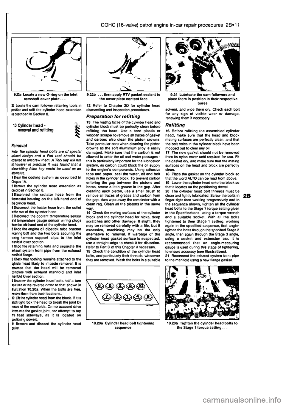
sequence
9.24 Lubricate the cam followers and place them in position in their respective bores solvent, and wipe them dry. Check each bolt for any sign of visible wear or damage, renewing them if necessary.
Refitting 18 Before refitting the assembled cylinder head, make sure that the head and block mating surfaces are perfectly clean, and that the bolt holes in the cylinder block have been mopped out to clear any oil, 17 The now gasket should not be removed from its nylon cover until required for use. Fit Ihe gasket dry, and make sure that the mating surfaces on the head and block are perfectly clean. 18 Place the gasket on the cylinder block so that the word ALTO can be read from above. 19 Lower the cylinder head onto the block so that it locates on the positioning dowel. 20 The cylinder head bolt threads must be clean and lightly lubricated. Screw the bolts in finger-tight then working progressively and in the sequence shown, lighten all the cylinder head bolts to the Stage 1 torquo setting given In the Specifications, using a torque wrench and a suitable socket. With all the bolts tightened to their Stage 1 setting, working again in the specified sequence, first angle-tighten the bolts through the specified Stage 2 angle, then again through the Stage 3 angle, using a socket and extension bar. It Is recommended that an angle-measuring gauge Is used during this stage ot tightening, to ensure accuracy (see Illustrations). 21 Reconnect the exhaust system front pipe to the manifold using a new flange gasket.
10.20b Tighten the cylinder head bolts to the Stago 1 torque setting ...
Page 79 of 225
Diesel engine in-car repair procedures
2C*11
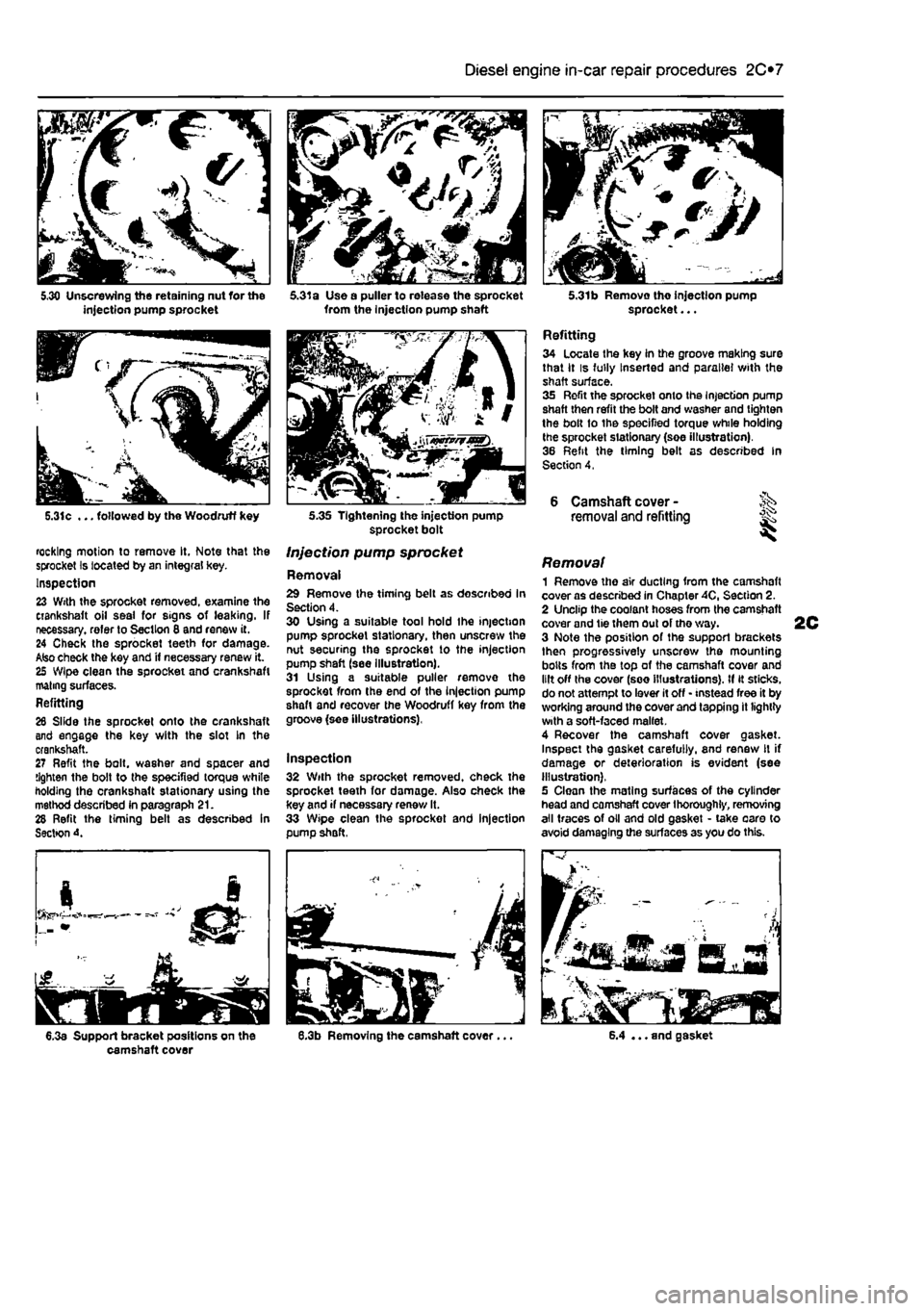
5.31c ... followed by the Woodruff key
rocking motion to remove It, Note that the sprocket Is located by an integral key. Inspection 23 With the sprocket removed, examine the crankshaft oil seal for signs of leaking. If necessary, refer to Section 8 and renew it. 24 Check the sprocket teeth for damage. Also check the key and if necessary renew it. 25 Wipe clean the sprocket and crankshaft mating surfaces. Refitting 26 Slide the sprocket onto the crankshaft and engage the key with the slot In the crankshaft. 27 Refit the bolt, washer and spacer and tighten the bolt to the specified torque white holding the crankshaft stationary using the method described in paragraph 21. 28 Refit the timing belt as described in Sectton 4.
6.3a Support bracket positions on the camshaft cover
5.31a Use a puller to release the sprocket from the injection pump shaft
5.35 Tightening the injection pump sprocket bolt
Injection pump sprocket
Removal 29 Remove the timing belt as described In Section 4. 30 Using a suitable tool hold Ihe injection pump sprocket stationary, then unscrew the nut securing the sprocket to the injection pump shaft (see illustration). 31 Using a suitable puller remove the sprocket from the end of the injection pump shaft and recover the Woodruff key from the groove (see illustrations),
Inspection 32 With the sprocket removed, check the sprocket teeth for damage. Also check the key and if necessary renew It. 33 Wipe clean the sprocket and injection pump shaft,
5.31b Removo tho injection pump sprocket...
Refitting 34 Locate the key in the groove making sure that it is fully Inserted and parallel with the shaft surface. 35 Refit the sprocket onto the Injection pump shaft then refit the bolt and washer and tighten the bolt to the specified torque while holding the sprocket stationary (soe illustration). 36 Refit the timing belt as described In Section 4,
6 Camshaft cover -removal and refitting ^
Removal 1 Remove the air ducting from the camshaft cover as described in Chapter 40, Section 2. 2 Unclip the coolant hoses from the camshaft cover and tie them out of tho way. 3 Note the position of the support brackets then progressively unscrew the mounting bolts from the top of the camshaft cover and lilt off the cover (see illustrations). If it sticks, do not attempt to lever it off • instead free it by working around the cover and tapping it lightly with a soft-faced mallet. 4 Recover the camshaft cover gasket. Inspect the gasket carefully, and renew It if damage or deterioration is evident (see illustration). 5 Clean the mating surfaces of the cylinder head and camshaft cover thoroughly, removing all traces of oil and old gasket • take oaro to avoid damaging the surfaces as you do this.
6.4 ... and gasket
Page 83 of 225
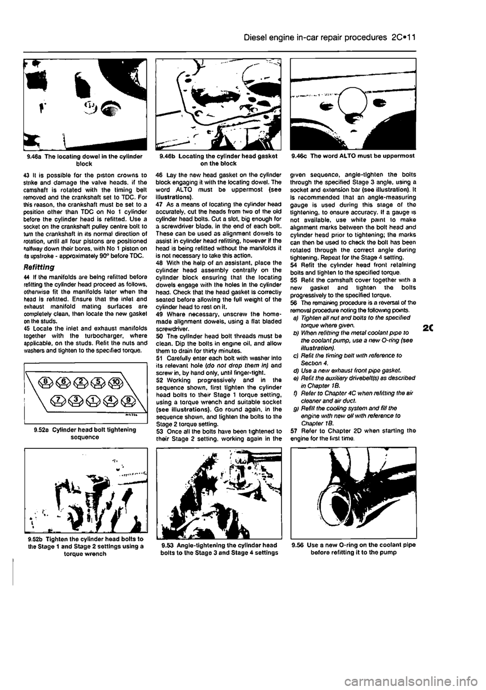
Diesel engine in-car repair procedures 2C*11
r
<3^
9.46a The locating dowel in the cylinder block 43 It is possible for the ptston crowns to stnke and damage the valve heads, if the camshaft is rotated v/ith the timing belt removed and the crankshaft set to TDC. For this reason, the crankshaft must be set to a position other than TDC on No t cylinder before the cylinder head is refitted. Use a socket on the crankshaft pulley centre bolt to turn the crankshaft in its normal direction of rotation, until all four pistons are positioned Halfway down their bores, v/ith No 1 piston on lis upstroke - approximately 90° before TDC.
Refitting 44 If the manifolds are being refitted before refitting the cylinder head proceed as follows, otherwise fit the manifolds later when the head is refitted. Ensure thai the inlet and exhaust manifold mating surfaces are completely clean, then locale the new gasket on the studs. 45 Locate the inlet and exhaust manifolds together with the turbocharger, where applicable, on the studs. Refit the nuts and washers and tighten to the specified torque.
sequence
f^/f
9.52b Tighten the cylinder head bolts to the Stage 1 and Stage 2 settings using a torque wrench
on the block 46 Lay the new head gasket on the cylinder block engaging it with the locating dowel. The word ALTO must be uppermost (see illustrations). 47 As a means of locating Ihe cylinder head accurately, cut the heads from two of the old cylinder head bolts. Cut a slot, big enough for a screwdriver blade, in the end of each bolt. These can be used as alignment dowels to assist in cylinder head refitting, however If the head is being refitted without the manifolds it is not necessary to take this action. 48 With the help of an assistant, place the cylinder head assembly centrally on the cylinder block ensuring thai the locating dowels engage with Ihe holes in the cylinder head. Check that the head gasket Is correctly seatod before allowing the full weight of the cylinder head to rest on it. 49 Where necessary, unscrew the home-made alignment dowels, using a flat bladed screwdriver. 50 The oyllnder head bolt threads must be clean. Dip the bolts in engine oil. and allow them to drain for thirty minutes. 51 Carefully enter each bolt with washer into its relevant hole (do not drop them in) and screw in, by hand only, until finger-tight. 52 Working progressively and In the sequence shown, first tighten the cylinder head bolts to their Stage 1 torque setting, using a torque wrench and suitable socket (see illustrations). Go round again, in the sequence shown, and tighten the bolls to the Stage 2 torque setting. 53 Once all the bolts have been tightened to their Stage 2 setting, working again in the
bolts to the Stage 3 and Stage 4 settings
9.46c The word ALTO must be uppermost
given sequence, angle-tighten the bolts through the specified Stage 3 angle, using a socket and extension bar (see illustration). It Is recommended that an angle-measuring gauge is used during this stage of the tightening, to ensure accuracy. If a gauge is not available, use white paint to make alignment marks between the bolt head and cylinder head prior to tightening; the marks can then be used to check tho bolt has been rotated through the correct angle during tightening. Repeat for the Stage 4 setting. 54 Refit the cylinder head front retaining bolts and tighten lo the specified torque. 55 Refit the camshaft cover together with a new gasket and tighten the bolts progressively to the specified torque. 56 The remaining procedure is a reversal of the removal procedure noting the following points. a) Tighten all nut and bolts to the specified torque where given. b) When refitting the metal coolant pipe to the coolant pump, use a new O-ring (see illustration). cj Refit the timing belt with reference to Section 4. d) Use a new exhaust front pipe gasket. e) Refit the auxiliary dhvebeltfs) as described in Chapter 1B. f) Refer to Chapter 4C when refitting the
air
cleaner and air duct. g) Refill the cooling system and fill the engine with new oil with reference to Chapter 1B. 57 Refer to Chapter 20 when starting the engine for the first time.
9.56 Use a new O-ring on the coolant pipe before refitting it to the pump
Page 103 of 225
2D*10 Engine removal and overhaul procedures
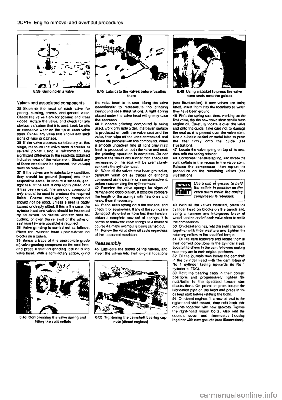
Valves and associated components 35 Examine the head of each vaive for pitting, burning, cracks, and general wear. Check the valve stem for scoring and wear ridges. Rotate the valve, and check lor any obvious indication that it Is bent. Look tor pits or excessive wear on the tip of each valve stem. Renew any valve that shows any such signs of wear or damage. 36 if the valve appears satisfactory at this stage, measure the vaive stem diameter at several points using a micrometer. Any significant difference in the readings obtained Indicates wear of the valve stem. Should any of these conditions be apparent, the valve(s) must be renewed. 37 If the valves are In satisfactory condition, they should be ground (lapped) into their respective seats, to ensure a smooth, gas-tight seal. If the seat is only tightly pitted, or if it has been re-cut, fine grinding compound only should be used to produce the required finish. Coarse valve-grinding compound should nor be used, unless a seat is badly bumed or deeply pitted, If this is the case, the cylinder head and valves should be Inspected by an expert, to decldo whether seat re-cutting, or even the renewal of the valve or seat insert (where possible) is required. 38 Valve grinding Is carried out as follows. Place the cylinder head upside-down on blocks on a bench. 39 Smear a trace of (the appropriate grade of) valve-gnndtng compound on the seat face, and press a suction grinding tool onto the valve head. With a semi-rotary action, grind
6.48 Compressing the vaive spring and fitting the split collets
them
the valve head to its seat, lifting the valve occasionally to redistribute tho grinding compound (see Illustration). A light spring placed under the valve head will greatly ease this operation 40 If coarse grinding compound Is being used, v/ork only until a dull, matt even surface Is produced on both the valve seal and the valve, then wipe off tho used compound, and repeat the process with fine compound. When a smooth unbroken ring ol light grey malt finish Is produced on both the valve and seat, the grinding operation is complete. Do not grind-In the valves any further than absolutely necessary, or the seat will be prematurely sunk into the cylinder head. 41 When all the valves have been ground-m, carefully wash off all traces of grinding compound using paraffin or a suitable solvent, before reassembling the cylinder head. 42 Examine the valve springs for signs of damage ano discoloration, If possible compare the length of the springs with new ones and renew them if necessary. 43 Stand each spring on a flat surface, and check ft tor squareness. If any of the springs are damaged, distorted or have lost mar tension, obtain a complete new set of springs. It Is normal to renew the valve springs as a matter of course if a major overhaul is being earned out. 44 Renew (he valve stem oil seals regardless of their apparent condition.
Reassembly 45 Lubricate the stems of the valves, and insert the valves into their original locations
6.53 Tightening the camshaft bearing cap nuts (diesel engines)
6.46 Using a socket to press the valve stem seals onto the guides
(see illustration). If new valves are being fitted, insert them Into the locations to which they have been ground. 46 Refit the spring sea( then, working on the first valve, dip the new valve stem sesl in fresh engine oil. Carefully locate it over the valve and onto the guide. Take care not to damage the seal as it Is passed over the valve stem. Use a suitable socket or metal tube to press the seal firmly onto the guide (sea Illustration). 47 Locate the valve spring on top of its seat, then refit the spring retainer. 48 Compress the valve spring, and locate the split collets in the recess in the valve stem. Release the compressor, then repeat the procedure on the remaining valves (see illustration)
Use a dab o) grease to hold Uiejitts* the collets In position on the HlNT valve stem while the spring compressor is released.
49 With ail the valves Installed, place the cylinder head on blocks on the bench and, using a hammer and Interposed block ol wood, top the end of each valve stem to settle the components. 50 On diesel engines, refit the swirl chambers together with their washers and tighten the retaining collars to the specified torque. 51 Oil the cam followers and locate them In their correct positions in the cylinder head. Locate the shims In the cam followers making sure they are in their original positions. 52 Oil the journals then locate the camshaft m the cylinder head with the cam lobes of No 1 cylinder facing upwards (ie No 1 cylinder at TDC). 53 Refit the bearing caps In their correct positions and progressively tighten the nuts/bolts to the specified torque (sea illustration). On petrol engines locate the lubrication pipe on Ihe head and press in the oil feed stub before refitting the bolts. 54 On diesel engines fit a new oil sea) to the right-hand side mount, then refit both side mounts together with new gaskets, Tighten the right-hand mount bolts. Also refit the coolant cover and thermostat housing together with new gaskets (see illustrations).
Page 106 of 225
Apply a smear of clean engine oil to the gudgeon pin. Slide it Into the piston and through the connecting rod small-end. Check that the piston pivots freely on the rod. then secure the gudgeon pin in position with two new circlips. Ensure that each circlip is correctly located In Its groove in the piston.
Refitting and big-end bearing running ciearance check 27 Prior to refitting the piston/connecting rod assemblies, it Is recommended that the big-end bearing running clearance is checked as follows. Big-end bearing running clearance check 28 Clean the backs of the bearing shells, and the bearing locations in both the connecting rod and bearing cap. 29 Press the bearing shells into their locations, ensuring that the tab on each shell engages in the notch In the connecting rod and cap. Take care not to touch any shell's bearing surface with your fingers. If the onginal bearing shells are being used for the check, ensure that they are refitted in their original locations. The clearance can be checked in either of two ways. 30 One method is to refit the big-end bearing cap to Ihe connecting rod, ensuring that they are litted the correct way around, with the bearing shells in place. Wilh the cap retaining bolls correctly tightened, use an internal micrometer or vernier caliper to measure the internal diameter of each assembled pair of bearing shells. If the diameter of each corresponding crankshaft journal is measured and Ihen subtracted from the bearing internal diameter, the result will be the big-end beanng running clearance. 31 The second, and more accurate method is to use a product called Plasligauge. Ensure that the bearing shells are correctly fitted then place a strand of Plastlgauge on each (cleaned) crankpin journal. 32 Refit the (clean) piston/connecting rod assemblies to the crankshaft, and refit the bg-end bearing caps, using the marks made or noted on removal to ensure that they are fitted the correct way around. 33 Tighten the beanng cap bolts taking care not to disturb the Plastlgauge or rotate the connecting rod dunng the tightening sequence. 34 Dismantle the assemblies without rotating the connecting rods. Use the scale pnnted on the Plastigauge envelope to obtain the big-end bearing running clearance. 35 If the clearance is significantly different from that expected, the bearing shells may be Ihe wrong size (or excessively worn. If the original shells are being re-used). Make sure mat no dirt or oil was trapped between Ihe bearing shells and the caps or block when the clearance was measured. If the Plastigauge was wider al one end than at the other, the crankshaft journal may be tapered.
2D*10 Engine removal and overhaul procedures
7.40a The arrow on the piston crown must point towards the timing belt end of the engine (petrol engine) 36 On completion, carefully scrape away all traces of the Plastigauge material from the crankshaft and bearing shells. Use your fingernail, or some other object which is unlikely to score the beanng surfaces.
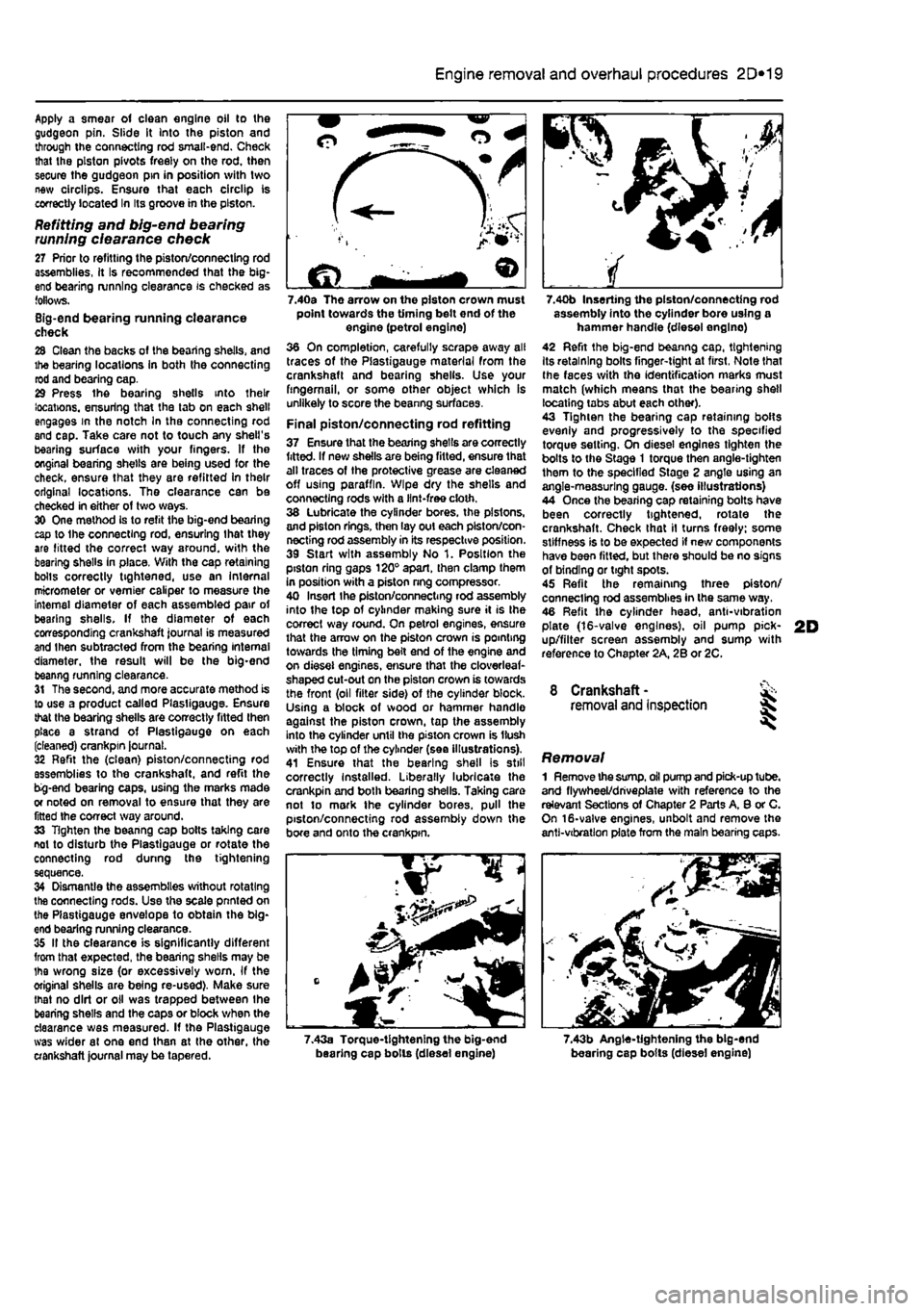
Final piston/connecting rod refitting 37 Ensure that the bearing shells are correctly fitted. If new shells are being fitted, ensure that alt traces of the protective grease are cleaned off using paraffin. Wipe dry the shells and connecting rods with a lint-free cloth. 38 Lubricate the cylinder bores, the pistons, and piston rings, then lay out each piston/con-necting rod assembly in its respective position. 39 Start with assembly No 1. Position the piston ring gaps 120° apart, then clamp them in position with a piston nng compressor. 40 Insert Ihe piston/connecting rod assembly into the top of cylinder making sure it is Ihe correct way round. On petrol engines, ensure that the arrow on the piston crown is pointing towards the timing belt end of the engine and on diesel engines, ensure that the cloverleaf-shaped cut-out on the piston crown is towards the front (oil filter side) of the cylinder block. Using a block of wood or hammer handle against the piston crown, tap the assembly into the cylinder until the piston crown is Hush with the top of the cylinder (sea illustrations). 41 Ensure that the bearing shell is still correctly Installed. Liberally lubricate the crankpin and both bearing shells. Taking care not to mark the cylinder bores, pull the piston/connecting rod assembly down the bore and onto the crankpin.
7.40b Inserting the piston/connecting rod assembly into the cylinder bore using a hammer handle (diesel englno) 42 Refit the big-end beanng cap, tightening Its retaining bolts finger-tight at first, Note that Ihe faces with the identification marks must match (which means that the bearing shell locating tabs abut each other). 43 Tighten the bearing cap retaining bolts evenly and progressively to the specified torque setting. On diesel engines tighten the bolts to the Stage 1 torque then angle-tighten them to the specified Stage 2 angle using an angle-measuring gauge, (see illustrations) 44 Once the bearing cap retaining bolts have been correctly tightened, rotate the crankshaft. Check that il turns freely; some stiffness is to be expected if new components have been fitted, but there should be no signs of binding or tight spots. 45 Refit the remaining three piston/ connecting rod assemblies in the same way. 46 Refit the cylinder head, anti-vibration plate (16-valve engines), oil pump pick-up/filter screen assembly and sump with reference to Chapter 2A, 2B or 2C.
8 Crankshaft -removal and inspection 35
Removal 1 Remove the
sump,
oil pump and pick-up tube, and flywheel/driveplate with reference to the relevant Sections of Chapter 2 Parts A, 8 or C. On 16-valve engines, unbolt and remove the anti-vibration plate from the main bearing caps.
7.43a Torque-tightening the big-end bearing cap bolls (diesel engine) 7.43b Angle-tightening the big-end bearing cap bolts (diesel engine)
Page 116 of 225
3*2 Cooling, heating and ventilation systems
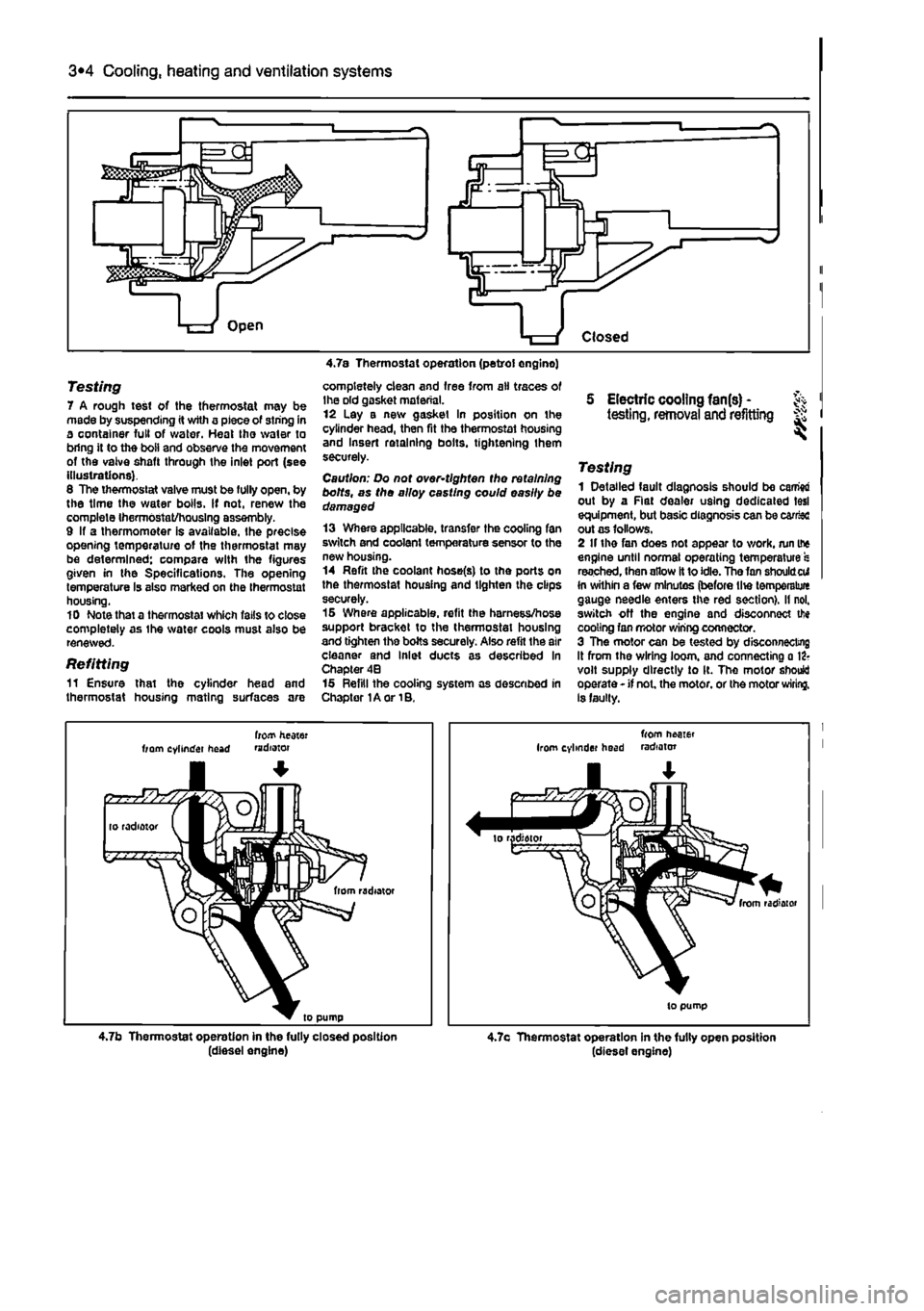
Testing 7 A rough test of the thermostat may be made by suspending it with a piece of siring in a container full of water. Heat tho water to bring it to the boii and observe the movement of the vaive shaft through the inlet port (see illustrations). 6 The thermostat valve must be fully open, by the time the water boils. If not, renew the complete IhermOstat/housIng assembly. 9 If a thermometer is available, the precise opening temperature of the thermostat may be determined; compare with the figures given in the Specifications. The opening temperature Is also marked on the thermostat housing. 10 Note that a thermostat which falls to close completely as ihe water cools must also be renewed.
Refitting 11 Ensure that the cylinder head and thermostat housing mating surfaces are
completely clean and free from ail traces of Ihe old gasket material. 12 Lay a new gasket In position on the cylinder head, then fit the thermostat housing and Insert retaining bolts, tightening them securely.
Caution: Do not over-tlghten tho retaining bolts, as tho alloy casting could easily be damaged 13 Where applicable, transfer the cooling fan switch and coolant temperature sensor to the new housing. 14 Refit the coolant hose(s) to the ports on the thermostat housing and lighten the clips securely. 15 Where applicable, refit the harness/hose support bracket to the thermostat housing and tighten the bolts securely. Also refit the air cleaner and Inlet ducts as described in Chapter 4B 15 Refill the cooling system as described in Chapter 1A or 1B.
5 Electric cooling fan(s) -testing, removal and refitting ^
Testing 1 Detailed fault diagnosis should be camw out by a Rat dealer using dedicated tesl equipment, but basic diagnosis can be car&c out as follows. 2 If the fan does not appear to work, run if* engine until normal operating temperature s reached, Ihen allow It to idle. The fan shouldcti In within a few minutes (before lite temperalure gauge needle enters the red section), il nol. switch off the engine and disconnect tfie cooling fan motor wiring connector. 3 The motor can be tested by disconnecting it from the wiring loom, and connecting a 12? volt supply directly to It. The motor should operate - if not. the motor, or the motor wiring. Is faulty.
frotf heater from cylinder head mdotor
4.7b Thermostat operation in the fully closed position (diesel engine)
from neoier Irom cylinder head radiator
4.7c Thermostat operation in the fully open position (diesel engine)
Page 141 of 225
Fuel system - diesel models 4C*3
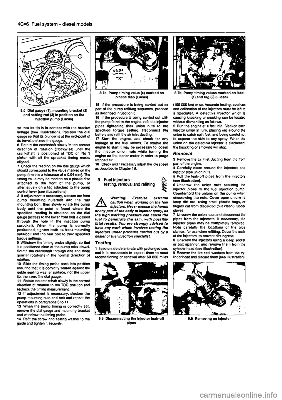
8.5 Dial gauge (1), mounting bracket (2) and setting rod (3) In position on the injection pump (Lucas)
so that Its tip Is In contact with the bracket linkage (see Illustration). Position the dial gauge so that its plunger is at the mid-point of its travel and zero the gauge. 6 Rotate the crankshaft slowly in the correct direction of rotation (clockwise) until the crankshaft is positioned at TDC on No 1 piston with ell the sprocket timing marks aligned. 7 Check the reading on the dial gauge which should correspond to the value marked on the pump (there is a tolerance of * 0.04 mm). The timing value may be marked on a plastic disc attached to the front of the pump, or alternatively on a tag attached to Ihe pump control lever (see illustrations). 8 If adjustment is necessary, slacken the front pump mounting nuts/bolt and the raar mounting bolt, then slowly rotate tne pump body until the point is found where the specified reading is obtained on the dial gauge (access to the lower front bolt is gained through the hole in the injection pump sprocket). When the pump Is correctly positioned, tighten both its front mounting nuta/bolt and the rear bolt to their specified torque settings. 9 Withdraw the timing probe slightly, so that it
8.7a Pump timing value (x) marked on plastic diso (Lucas)
15 If the procedure is being carried out as part of the pump refilling sequence, proceed as described in Section 5. 16 If the procedure is being carried out with the pump fitted to the engine, refit the injector pipes tightening their union nuts to the specified torque setting. Reconnect the battery and refit the air inlet ducting. 17 Start the engine, and check for any leakage at the fuel unions. To enable the engine to start it may be necessary to loosen tho injector union nuts while turning the engine on the starter motor in order to purge trapped air. 18 Check and If necessary adjust the Idle speed as described In Chapter 1B.
9 Fuel Injectors -testing, removal and refitting Sk ^
A
Warning: Exercise extreme caution when working on the fuel injectors. Never expose the hands or any part of the body to Injector spray, as the high working pressure can cause the fuel to pen ot rate the skin, with possibly fatal results. You are strongly advised to have any work which involves testing the injectors under pressure carried out by a dealer or fuel Injection specie list.
Testing 1 Injectors do deteriorate with prolonged uso, and it is reasonable to expect them to need reconditioning or renewal after 60 000 miles
8.7b Pump timing values marked on label (1) and tag (2) (Lucas)
(100 000 km) or so. Accurate testing, overhaul and calibration of the Injectors must be left to a specialist. A defective injector which Is causing knocking or smoking can be located without dismantling as follows. 2 Run the engine at a fast idle. Slacken each Injector union In turn, placing rag around the union to catch spilt fuel, and being careful not to exposa the skin to any spray. When tho union on the defective Injector is slackened, the knocking or smoking will stop.
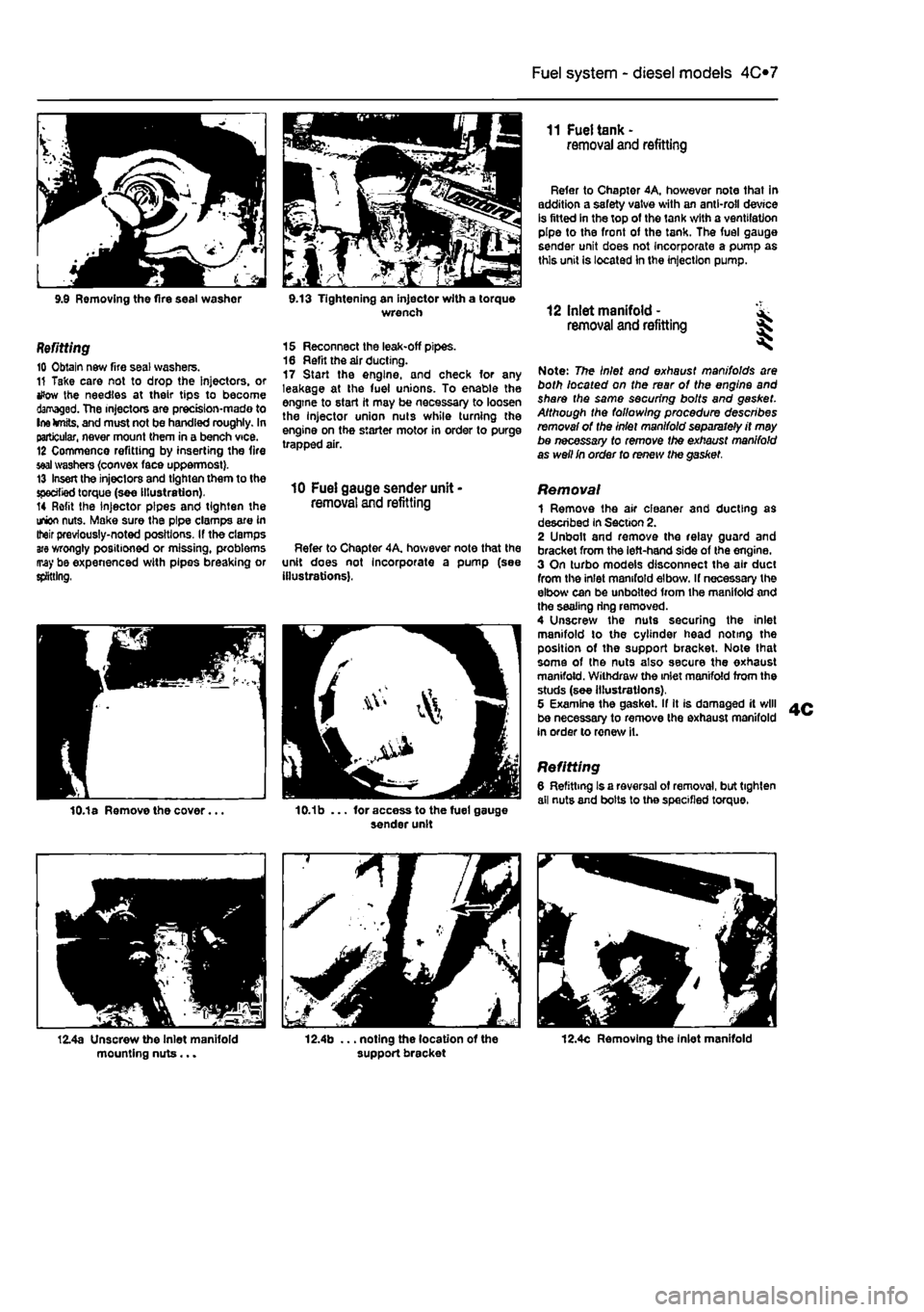
Removal 3 Remove ihe air Inlet ducting from tho front part of the onglne. 4 Carefully clean around the Injectors and injector pipe union nuts. 5 Pull the leak-off pipes from the injectors (see illustration). 6 Unscrow the union nuts securing Ihe injector pipes to the fuel Injection pump. Counterhold the unions on the pump when unscrewing the nuts. Cover open unions lo keep dirt out, using small plastic bags, or fingers cut from discarded (but clean!) rubber gloves. 7 Unscrew the union nuts and disconnect the pipes from the ln|ectors, If necessary, the Injector pipes may be completely removed-Note carefully the locations of the pipe clamps, for use when refitting. Cover tho onds ot (he injectors, to prevent dirt ingress. 8 Unscrew the injectors using a deep socket or box spanner, and remove Ihem from the cylinder head (see Illustration). 9 Recover the tire seal washers from the cy-linder head and discard them (see illustration).
9.5 Disconnecting the Injector leak-off pipes 9.8 Removing an injector
Page 142 of 225
Fuel system - diesel models
4C*3
9.9 Removing the fire seal washor 9.13 Tightening an injector with a torque wrench
Refitting 10 Obtain new fire seal washers. 11 Take care not to drop the Injectors, or tfow the needles at their tips to become damaged. The injectors are prectsion-mado to Ine knits, and must not be handled roughly. In particular, never mount them in a bench vice. 12 Commence refitting by inserting the fire
seal
washers {convex face uppermost}. 13 Insert the injectors and tighten them to the specified torque (see illustration). 14 Refit the injector pipes and tighten the union nuts. Make sure the pipe clamps are in Iteir previously-noted positions. If the clamps
are
wrongly positioned or missing, problems may be expenenced with pipes breaking or splitting,
15 Reconnect the leak-off pipes. 16 Refit the air ducting. 17 Start the engine, and check for any leakage at the fuel unions. To enable the engine to start it may be necessary to loosen the Injector union nuts while turning the engine on the starter motor in order to purge trapped air.
10 Fuel gauge sender unit -removal and refitting
Refer to Chapter 4A, hov/ever note that the unit does not Incorporate a pump (see illustrations).
11 Fuel tank -removal and refitting
Refer to Chapter 4A, however note that in addition a safety valve with an anti-roll device is fitted in the top of the tank with a ventilation pipe to the front of the tank. The fuel gauge sender unit does not Incorporate a pump as this unit is located In the injection pump.
12 Inlet manifold - ^ removal and refitting %
Note: The Inlet and exhaust manifolds are both located on the rear of the engine and share the same securing bolts and gasket. Although the following procedure describes removal of the Inlet manifold separately it may be necessary to remove the exhaust manifold as well In order to renew the gasket.
Removal 1 Remove the air cleaner and ducting as described in Section 2. 2 Unbolt and remove the relay guard and bracket from the left-hand side of the engine. 3 On turbo models disconnect the air duct from the inlet manifold elbow. If necessary the elbow can be unbolted from the manifold and the sealing ring removed. 4 Unscrew the nuts securing the inlet manifold to the cylinder head noting the position of the support bracket. Note lhat some of the nuts also secure the exhaust manifold. Withdraw the inlet manifold from the studs (see illustrations), 5 Examine the gasket. If It is damaged it will be necessary to remove the exhaust manifold in order to renew it.
Refitting 6 Refitting Is a reversal of removal, but tighten all nuts and bolts lo the specified torque.
12.4c Removing the Inlet manifold