water sensor temperature FIAT PUNTO 1996 176 / 1.G Workshop Manual
[x] Cancel search | Manufacturer: FIAT, Model Year: 1996, Model line: PUNTO, Model: FIAT PUNTO 1996 176 / 1.GPages: 225, PDF Size: 18.54 MB
Page 44 of 225
ib-8 Every 10 000 miles - diesel models
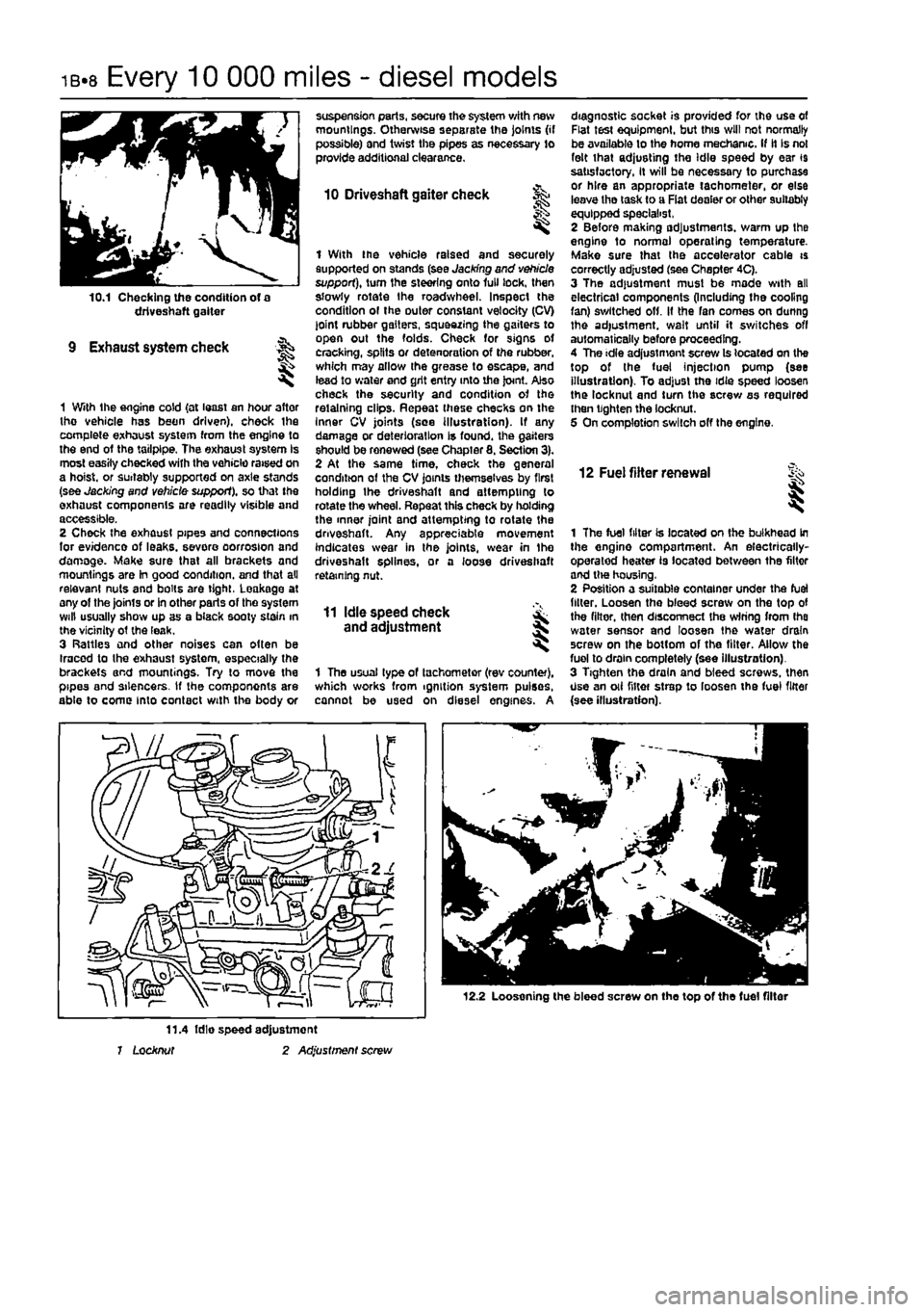
10.1 Checking the condition of a driveshaft gaiter
9 Exhaust system check
1 With the engine cold {at least an hour after tho vehicle has been driven), check ihe complete exhaust system from the engine to the end of the tailpipe. The exhaust system Is most easily checked with the vehicle raised on a hoist, or suitably supported on axle stands (see Jacking and vehicle support), so that the exhaust components are readily visible and accessible. 2 Check the exhaust pipes and connections for evidence of leaks, severe oorrosion and damage. Make sure that all brackets and mountings are In good condition, and that all relevant nuts and bolts are tight, Leakage at any of the joints or in other parts of tho system will usually show up as a black sooty stain in the vicinity ot the leak. 3 Rattles and other noises can often be Iracod to the exhaust system, especially the brackets and mountings. Try to move the pipes and silencers. If the components are able to come into contact with the body or
suspension parts, secure the system with new mountings. Otherwise separate the joints (if possible) and twist the pipes as necessary to provide additional clearance.
10 Driveshaft gaiter check
I
1 With the vehicle raised and securely supported on stands (see Jacking and vehicle support), turn the steering onto lull lock, then slowly rotate the roadwheel. Inspect the condition ol the outer constant velocity (CV) joint rubber gaiters, squeezing the gaiters to open out the folds. Check for signs ot cracking, splits or detenoration of the rubber, which may allow the grease to escape, and lead to water and grit entry into the joint. Also check the security and condition of the retaining clips. Repeat these checks on the Inner CV joints (see illustration). If any damage or deterioration is found, the gaiters should be renewed (see Chapter 8. Section 3). 2 At the same time, check the general condition of the CV joints themselves by first holding the driveshaft and attempting to rotate the wheel. Repeat this check by holding the inner joint and attempting to rotate the driveshaft. Any appreciable movement indicates wear in the joints, wear in Ihe driveshaft splines, or a loose driveshaft retaining nut.
11 Idle speed check and adjustment
1 The usual type of tachometer (rev counter), which works from ignition system pulses, cannot be used on diesel engines. A
diagnostic socket is provided for the use of Flat test equipment, but this will not normally be available to the home mechanic. If it Is not felt that adjusting the Idle speed by ear 19 satisfactory, It will be necessary to purchase or hire an appropriate tachometer, or else leave tho task to a Fiat dealer or other suitably equipped specialist, 2 Before making adjustments, warm up the engine to normal operating temperature. Make sure that the accelerator cable is correctly adjusted (see Chapter 4C). 3 The adjustment must be made with all electrical components (Including the cooling fan) switched off. It the fan comes on dunng the adjustment, wait until it switches off automatically before proceeding. 4 The idle adjustment screw Is located on the top of the fuel injection pump (see illustration). To adjust the idie speed loosen the locknut and turn the screw as required then tighten the locknut. 5 On completion switch off the engine.
12 Fuel filter renewal i
1 The fuel filter is located on the bulkhead in the engine compartment. An electrically-operated heater is located between the filter and tlw housing, 2 Position a suitable container under the fuel filler. Loosen tho bleed screw on the top of the filter, then disconnect the wiring from Ihe water sensor and loosen the water drain screw on the bottom of the filter. Allow the fuel to drain completely (see illustration). 3 Tighten the drain and bleed screws, then Use an oii niter strep to loosen the fuel filter {see illustration).
12.2 Loosening the bleed screw on the top of the fuel filter
11.4 fdie speed adjustment 1 Locknut 2 Adjustment screw
Page 71 of 225
DOHC (16-valve) petrol engine in-car repair procedures 2B*11
camshaft cover plate... 25 Locate the cam follower retaining tools in position and refit the cylinder head extension
as
described In Section 8.
10
Cylinder head - &
removal and
refitting S
Removal Note; The cylinder head bolts are of special
sekned
design and a Fiat tool should be
obtained
to unscrew them. A Ton key will not
JSt however
in practise It was found that a dose-httlng Alien key could be used as an itemative. 1 Drain the cooling system as described in Chapter 1A. 2 Remove the cylinder head extension as oescAbed
m
Section 8. 3 Disconnect the radiator hose from the thermostat housing on the left-hand end of
Ihe
cylinder head. 4 Disconnect the heater hose from the outlet
at the
rear of the cylinder head. 5 Disconnect the coolant temperature sensor md temperature gauge sensor wiring plugs
torn
the left-hand end of the cylinder head. 9 Undo the engine oil dipstick tube bracket retaining bolt and the two bolts securing the wing harness support clips to the inlet marriold lower section. 7 Undo Ihe retaining nuts and separate the ixhaust system front pipe from the exhaust manifold flange.
8
Check that nothing remains attached to the cinder head likely to impede removal. It Is assumed that the head will be removed complete with exhaust manifold and inlet manifold lower section. 9 Unscrew the cylinder head bolts half a turn K
e
time in the reverse order to that shown in (lustration 10.20a. When the bolts are free. «mwe them from their locations.. Id Lift the cylinder head from the block. If it is stuck tight rock the head to break the joint by mans of the manifolds. On no account drive
levers
into the gasket Joint, nor attempt to tap tf« head sideways, as it is located on positioning dowels. 11 Remove and discard the cylinder head gasket.
JK'
l^. 9.22b ... then apply RTV gasket sealant to the cover plate contact face 12 Refer to Chapter 20 for cylinder head dismantling and inspection procedures. Preparation for refitting 13 The mating faces of the cylinder head and cylinder block must be perfectly dean before refitting the head. Use a hard plastic or wooden scraper to remove all traces of gasket and carbon; also clean the piston crowns, Take particular care when cleaning the piston crowns as the soft aluminium alloy is easily damaged. Make sure that the carbon is not allowed to enter the oil and water passages -this Is particularly important for the lubncahon system, as carbon could block the oil supply to the engine's components. Using adhesive tape and paper, seal the water, oil and bolt holes in the cylinder block. To prevent carbon entering the gap between the pistons and bores, smear a little grease In the gap. After cleaning each piston, use a small brush to remove all traces of grease and carbon from the gap. then wipe away the remainder with a clean rag. Clean all the pistons in the same way. 14 Check the mating surfaces of the cylinder block and the cylinder head for nicks, deep scratches and other damage. If slight, they may be removed carefully with a file, but If excessive, machining may be the only alternative to renewal. If warpage of the cylinder head gasket surface Is suspected, use a straight-edge to check it for distortion. Refer to Part 0 of this Chapter if necessary. 15 Check the condition of the cylinder head bolts, and particularly their threads, whenever they are removed. Wash the bolts In a suitable
sequence
9.24 Lubricate the cam followers and place them in position in their respective bores solvent, and wipe them dry. Check each bolt for any sign of visible wear or damage, renewing them if necessary.
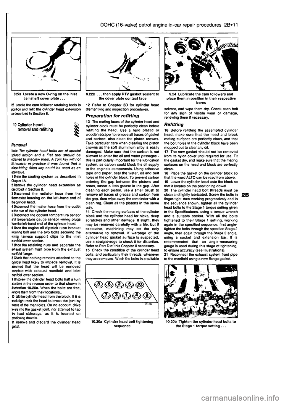
Refitting 18 Before refitting the assembled cylinder head, make sure that the head and block mating surfaces are perfectly clean, and that the bolt holes in the cylinder block have been mopped out to clear any oil, 17 The now gasket should not be removed from its nylon cover until required for use. Fit Ihe gasket dry, and make sure that the mating surfaces on the head and block are perfectly clean. 18 Place the gasket on the cylinder block so that the word ALTO can be read from above. 19 Lower the cylinder head onto the block so that it locates on the positioning dowel. 20 The cylinder head bolt threads must be clean and lightly lubricated. Screw the bolts in finger-tight then working progressively and in the sequence shown, lighten all the cylinder head bolts to the Stage 1 torquo setting given In the Specifications, using a torque wrench and a suitable socket. With all the bolts tightened to their Stage 1 setting, working again in the specified sequence, first angle-tighten the bolts through the specified Stage 2 angle, then again through the Stage 3 angle, using a socket and extension bar. It Is recommended that an angle-measuring gauge Is used during this stage ot tightening, to ensure accuracy (see Illustrations). 21 Reconnect the exhaust system front pipe to the manifold using a new flange gasket.
10.20b Tighten the cylinder head bolts to the Stago 1 torque setting ...
Page 114 of 225
3*2 Cooling, heating and ventilation systems
1 General information and precautions
Genera/ Information The engine cooling/cabin heating system is ol pressurised type, comprising a coolant pump driven by the camshaft timing belt (petrol engine models) or auxiliary drlvebelt (diesel engine models), a crossllow radiator, a coolant expansion tank, an electric cooling fan, a thermostat, heater matrix, and all associated hoses and switches. The system functions as follows: Ihe coolant pump circulates cold water around the cylinder block and head passages, and through the Inlet manifold, heater matrix and throttle body to the thermostat housing. When the engine Is cold, the thermostat remains closed and prevents coolant from circulating through the radiator. When the coolant reaches a predetermined temperature, the thermostat opens, and the coolant passes through the top hose to the radiator. As the coolant circulates through the radiator, it is cooled by the in-rush of air when the car is in forward motion. The airllow is supplemented by the action of the electric cooling fan. when necessary, As the temperature of the coolant in the radiator drops, it flows to the bottom of the radiator by convection, and passes out through the bottom hose to the coolant pump - the cycle is then repeatod, When the engine is at normal operating temperature, the coolant expands, and some of It is displaced into the expansion tank. Coolant collects In the tank, and ts returned to Ihe radiator when the system cools. On petrol engine models, the expansion tank is integrated into the side of the radiator. On diesel engine models, and certain petrol engine models with air conditioning, the tank is a separate unit, mounted on the right hand side of the engine compartment. On turbo diesel engine models, the coolant is also passed through a supplementary engine oil cooler, to assist In controlling the engine lubricant temperature. Tho electric cooling fan mounted in front of the radiator is controlled by a thermostatic switch. At a predetermined coolant temperature, the swilch/sensor actuates the tan lo provide additional airflow through the radiator, The switch cuts the electrical supply to the Ion when the coolant temperature has dropped below a preset threshold (see Specifications).
Precautions
A
Warning: Do not attempt to remove the expansion tank pressure cap, or to disturb any part of the cooling system, whlio the engine is hot, as then is a high risk of scalding, tf the expansion tank pressure cap must be removed before the
engine and radiator have fulty cooled (even though this is not recommended?, the pressure in the cooling system must first be relieved. Cover the cap with a thick layer of cloth, to avoid scalding, and slowly unscrew the pressuro cap until a hissing sound Is heard. When the hissing stops, indicating that the pressure has reduced, slowly unscrew the pressure cap until it can be removed; If more hissing sounds are heard, wait until they have stopped before unscrewing the cap completely. At all times, keep your face well away from the pressure cap opening, and protect your hands.
A
Warning: Do not allow antifreeze to come into contact with your skin, or with the painted surfaces of the vehicle. Rinse off spills immediately, with plenty of water. Never leave antifreeze lying around in an open container, or In a puddle In the driveway or on the garage floor. Children and pets are attracted by its sweet smell, but antifreeze can be fatal tf ingested.
A
Warning: If the engine is hot, the electric cooling fan may start rotating even if the engine and ignition are switched off. Be careful to keep your hands, hair, and any loose clothing well clear when working In the engine compartment.
2 Cooling system hoses - f&> disconnection and renewal ^
1 The number, routing and pattern of hoses will vary according to model, but the same basic procedure applies. Before commencing work, make sure that the new hoses are to hand, along wilh new hose clips if needed, it is good practice to renew the hose clips at the same time as the hoses. 2 Drain the cooling system, as described in Chapter 1A or 18, saving the coolant if it is fit for re-use. Apply a little penetrating oil onto the hose clips if they are corroded. 3 Release the hose clips from the hose concerned. Three types of clip are used; worm-drive. spring and 'sardine-can'. The worm-drive clip is released by turning its screw anti-clockwise. The spring clip Is released by squeezing Its tags together with pliers, at the same time working the cbp away from the hose stub. The sardine-can clips are not re-usable, and are best cut off with snips or side cutters. 4 Unclip any wires, cables or other hoses which may be attached to the hose being removed. Make notes for reference when reassembling If necessary. 5 Release the hose from its stubs with a twisting motion. Be careful not to damage the stubs on deltcate components such as the radiator, or thermostat housings. If the hose Is stuck fast, the best course is often to cut it off using a sharp knife, but again be careful not to damage the stubs.
6 Before fitting the new hose, smear the stubs with washing-up liquid or a suitable rubber lubricant to aid fitting. Do not use oil or grease, which may attack the rubber. 7 Fit the hose clips over the ends of the hose, then fit the hose over its stubs. Work the hose Into position. When satisfied, locate and tighten the hose dips. 6 Refill the cooling system as described In Chapter 1A or 1B. Run the engine, and chock that there are no leaks. 9 Recheck the tightness of Ihe hose clips on any new hoses after a few hundred miles. 10 Top-up the coolant level if necessary.
3 Radiator -
removal,
inspection and refitting
Removal Note: If leakage is the reason for removing
the
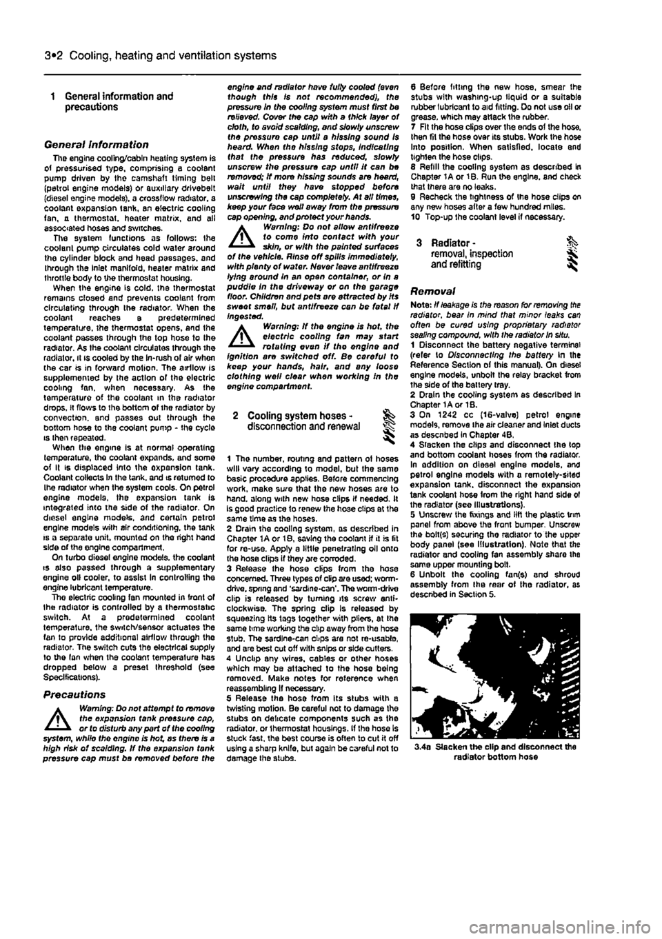
radiator, bear In mind that minor leaks can often be cured using proprietary radiator sealing compound, with the radiator in situ. 1 Disconnect the battery negative terminal (refer to Disconnecting the battery In the Reference Section of this manual). On diesel engine models, unbolt the relay bracket from the side of the battery tray. 2 Drain the cooling system as described In Chapter 1A or 1B. 3 On 1242 cc (16-valve) petrol engine models, remove the air cleaner and Inlet ducts as desenbed In Chapter 4B, 4 Slacken the clips and disconnect Ihe (op and bottom coolant hoses from the radiator. In addition on diesel engine models, and petrol engine models with a remotely-sited expansion tank, disconnect the expansion tank coolant hose from the right hand side ol the radiator (see Illustrations), 5 Unscrew the fixings and lift the plastic trim panel from above the front bumper Unscrew the bolt(s) securing tho radiator to the upper body panel (see Illustration). Note that the radiator and cooling fan assembly share the same upper mounting bolt. 6 Unbolt the cooling fan(e) and shroud assembly from Ihe rear ot the radiator, as described in Section 5.
3.4a Slacken the clip and disconnect the radiator bottom hose
Page 116 of 225
3*2 Cooling, heating and ventilation systems
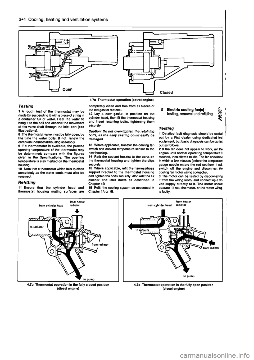
Testing 7 A rough test of the thermostat may be made by suspending it with a piece of siring in a container full of water. Heat tho water to bring it to the boii and observe the movement of the vaive shaft through the inlet port (see illustrations). 6 The thermostat valve must be fully open, by the time the water boils. If not, renew the complete IhermOstat/housIng assembly. 9 If a thermometer is available, the precise opening temperature of the thermostat may be determined; compare with the figures given in the Specifications. The opening temperature Is also marked on the thermostat housing. 10 Note that a thermostat which falls to close completely as ihe water cools must also be renewed.
Refitting 11 Ensure that the cylinder head and thermostat housing mating surfaces are
completely clean and free from ail traces of Ihe old gasket material. 12 Lay a new gasket In position on the cylinder head, then fit the thermostat housing and Insert retaining bolts, tightening them securely.
Caution: Do not over-tlghten tho retaining bolts, as tho alloy casting could easily be damaged 13 Where applicable, transfer the cooling fan switch and coolant temperature sensor to the new housing. 14 Refit the coolant hose(s) to the ports on the thermostat housing and lighten the clips securely. 15 Where applicable, refit the harness/hose support bracket to the thermostat housing and tighten the bolts securely. Also refit the air cleaner and Inlet ducts as described in Chapter 4B 15 Refill the cooling system as described in Chapter 1A or 1B.
5 Electric cooling fan(s) -testing, removal and refitting ^
Testing 1 Detailed fault diagnosis should be camw out by a Rat dealer using dedicated tesl equipment, but basic diagnosis can be car&c out as follows. 2 If the fan does not appear to work, run if* engine until normal operating temperature s reached, Ihen allow It to idle. The fan shouldcti In within a few minutes (before lite temperalure gauge needle enters the red section), il nol. switch off the engine and disconnect tfie cooling fan motor wiring connector. 3 The motor can be tested by disconnecting it from the wiring loom, and connecting a 12? volt supply directly to It. The motor should operate - if not. the motor, or the motor wiring. Is faulty.
frotf heater from cylinder head mdotor
4.7b Thermostat operation in the fully closed position (diesel engine)
from neoier Irom cylinder head radiator
4.7c Thermostat operation in the fully open position (diesel engine)
Page 117 of 225
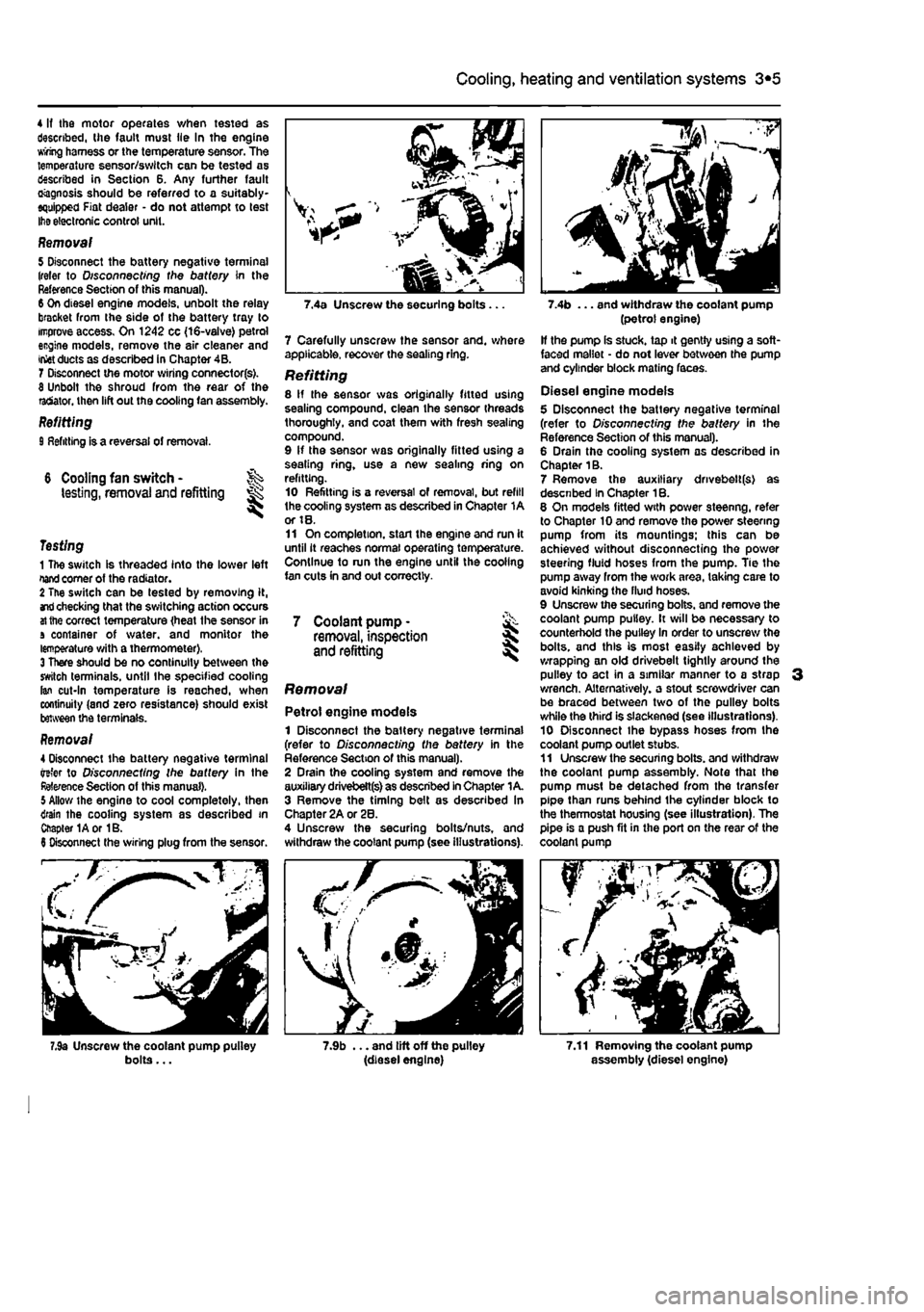
3*2 Cooling, heating and ventilation systems
4 If the motor operates when tested as described, (he fault must lie In the engine wring harness or the temperature sensor. The temperature sensor/switch can be tested as described in Section 6. Any further fault Diagnosis should be referred to a suitably-equipped Fiat dealer - do not attempt to test
Ihe
electronic control unit.
Removal 5 Disconnect the battery negative terminal (refer to D/scon oecf/ng the battery in the Reference Section of this manual). 6 On diesel engine models, unbolt the relay bracket from the side of the battery tray to improve access. On 1242 cc {16-valve) petrol engine models, remove the air cleaner and
inset
ducts as described in Chapter 4B. 1 Disconnect the motor wiring connectorfs). 8 Unbolt the shroud from the rear of the ratiator. then lift out the cooling fan assembly. Refitting 9 Refitting is a reversal of removal
6 Cooling fan switch -testing, removal and refitting ^
Testing 1 The switch is threaded into the lower left
nand
comer of the radiator. 2 The switch can be tested by removing it,
and
checking that the switching action occurs
at
the correct temperature {heat the sensor in a container of water, and monitor the temperature with a thermometer). 3 There should be no continuity between the switch terminals, until Ihe specified cooling fan cut-In temperature Is reached, when continuity (and zero resistance) should exist between the terminals.
Removal 4 Disconnect the battery negative terminal refer to Disconnecting the battery in the Reference Section of this manual). 5 Allow the engine to cool completely, then drain the cooling system as described in Chapter 1Aor 1B. 6 Disconnect the wiring plug from the sensor.
bolts...
7 Carefully unscrew the sensor and. whore applicable, recover the sealing ring. Refitting 8 If the sensor was originally fitted using sealing compound, clean the sensor threads thoroughly, and coat them with fresh sealing compound. 9 If the sensor was originally fitted using a sealing ring, use a new sealing ring on refitting. 10 Refitting is a reversal of removal, but refill the cooling system as described in Chapter 1A or 18. 11 On completion, start the engine and run it until it reaches normal operating temperature. Continue to run the engine until the cooling fan cuts in and out correctly.
7 Coolant pump • & removal, inspection 5 and refitting
Removal
Petrol engine models 1 Disconnect the battery negative terminal (refer to Disconnecting the battery in the Reference Section of this manual). 2 Drain the cooling system and remove the auxiliary drivebett(s) as described In Chapter 1 A. 3 Remove the timing belt as described In Chapter 2A or 28. 4 Unscrew the securing bolts/nuts, and withdraw the coolant pump (see illustrations).
7.9b ... and lift off the pulley (diesel engine)
(petrol engine) If the pump Is stuck, tap it gently using a soft-faced mallet - do not lever between the pump and cylinder block mating faces.
Diesel engine models 5 Disconnect the battery negative terminal (refer to D/s connecting the battery in the Reference Section of this manual). 6 Drain the cooling system as described in Chapter 1B. 7 Remove the auxiliary drivebelt(s) as descnbed In Chapter 1B. 6 On models fitted with power steenng, refer to Chapter 10 and remove the power steering pump from its mountings; this can be achieved without disconnecting the power steering fluid hoses from the pump. Tie the pump away from the work area, taking care to avoid kinking the fluid hoses. 9 Unscrew the securing bolts, and remove the coolant pump pulley. It will be necessary to counterhold the pulley In order to unscrew the bolts, and this is most easily achieved by wrapping an old drivebelt tightly around the pulley to act in a similar manner to a strap 3 wrench. Alternatively, a stout screwdriver can be braced between two of the pulley bolts while the third is slackened (see illustrations). 10 Disconnect ihe bypass hoses from the coolant pump outlet stubs. 11 Unscrew the securing bolts, and withdraw the coolant pump assembly. Note that the pump must be detached from the transfer pipe than runs behind the cylinder block to the thermostat housing (see illustration). The pipe is a push fit in the port on the rear of the coolant pump
7.11 Removing the coolant pump assembly (diesel engine)