wiper FIAT PUNTO 1996 176 / 1.G Workshop Manual
[x] Cancel search | Manufacturer: FIAT, Model Year: 1996, Model line: PUNTO, Model: FIAT PUNTO 1996 176 / 1.GPages: 225, PDF Size: 18.54 MB
Page 3 of 225
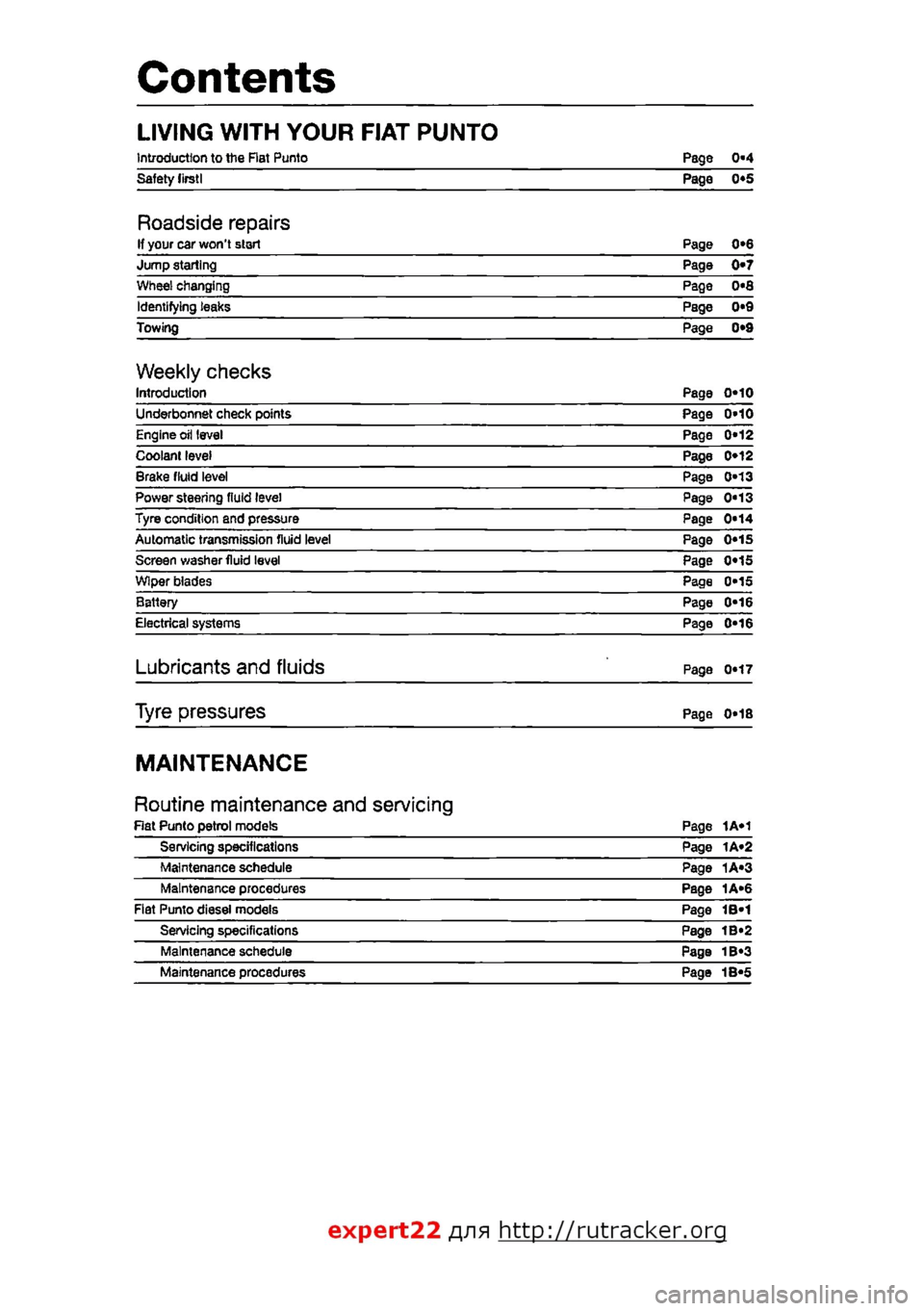
Contents
LIVING WITH YOUR FIAT PUNTO
Introduction to the Rat Punto Page 0-4 Safety lirstl Page 0*5
Roadside repairs If your car won't start Page 0*6 Jump starting Page 0*7 Wheel changing Page 0«8 Identifying teaks Page 0*9 Towing Page 0*9
Weekly checks Introduction Page 0*10 Underbonnet check points Page 0»10 Engine oil level Page 0*12 Coolant level Page 0*12 Brake fluid level Page 0*13 Power steering fluid level Page 0"13 Tyre condition and pressure Page 0*14 Automatic transmission fluid level Page 0«1S Screen washer fluid level Page 0«1S Wiper blades Page 0*15 Battery Page 0*16 Electrical systems Page 0-16
Lubricants and fluids Page 0*17
Tyre pressures Page 0*18
MAINTENANCE
Routine maintenance and servicing Rat Punto petrol models Page 1A«1 Servicing specifications Page 1A«2 Maintenance schedule Page 1A«3 Maintenance procedures Page 1A«6 Fiat Punto diesei models Page 1B-1 Servicing specifications Page 1B«2 Maintenance schedule Page 1B«3 Maintenance procedures Page 1B«5
expert22 fl/ia http://rutracker.org
Page 8 of 225
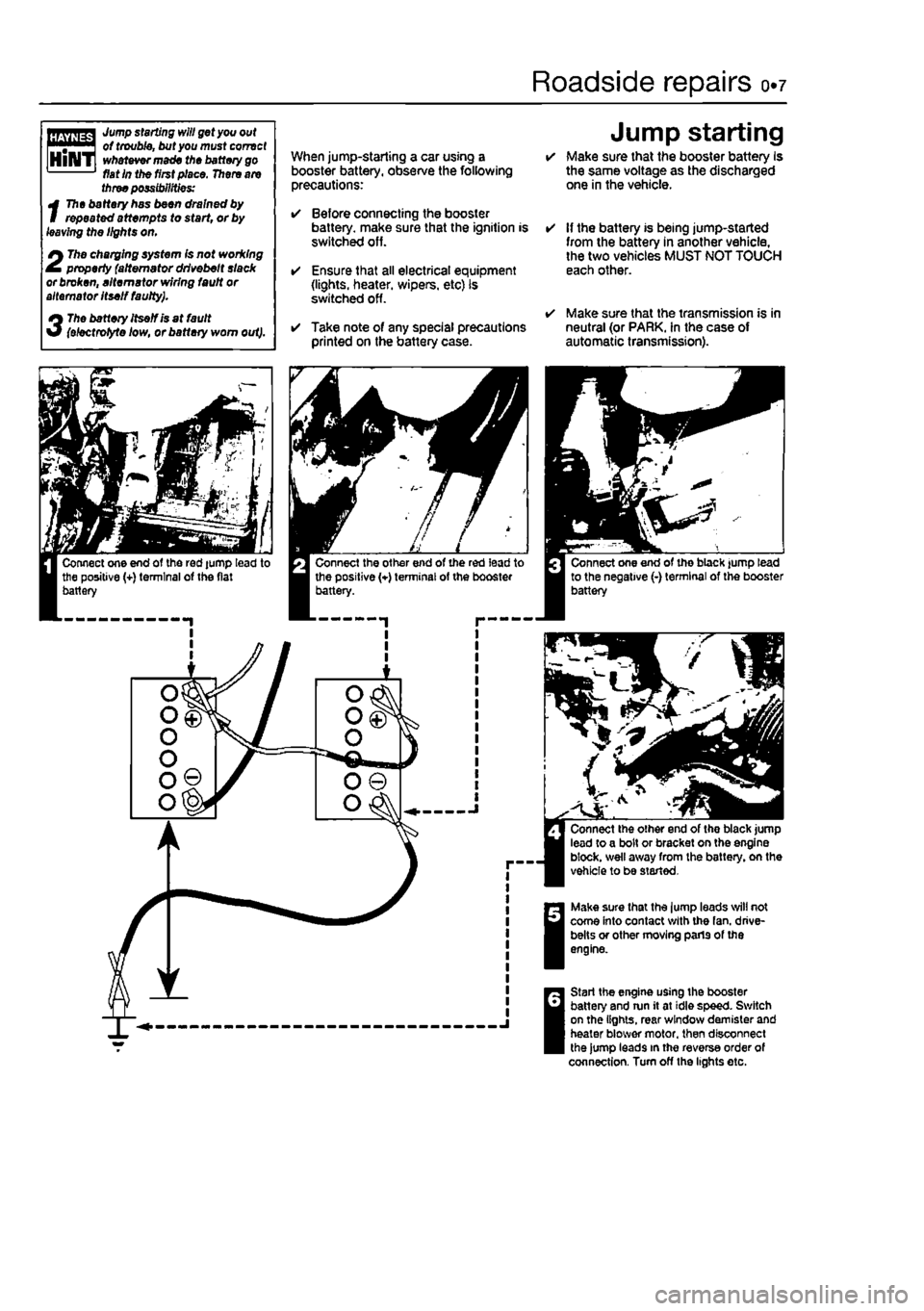
Roadside repairs 0.7
I Jump starting will get you out of trouble, but you must correct | whatever made the battery go fiat in the first place. There are three possibilities:
t
The battery has been drained by repeated attempts to start, or by leaving the lights on.
2
The charging system (s not working property (alternator drivebelt slack or broken, alternator wiring fault or alternator Itself faulty).
3
The battery Itself is at fault (ehctrotyte low, or battery worn out).
When jump-starling a car using a booster battery, observe the following precautions:
• Before connecting the booster battery, make sure that the ignition is switched off.
• Ensure that all electrical equipment (lights, heater, wipers, etc) is switched off.
• Take note of any special precautions printed on the battery case.
Jump starting • Make sure that the booster battery Is the same voltage as the discharged one in the vehicle.
• If the battery is being jump-started from the battery in another vehicle, the two vehicles MUST NOT TOUCH each other.
• Make sure that the transmission is in neutral (or PARK. In the case of automatic transmission).
Make sure that the lump leads will not come into contact with the fan. drive-belts or other moving parts of the engine.
Start the engine using the booster battery and run it at idle speed. Switch on the lights, rear window demister and heater blower motor, then disconnect the jump leads in the reverse order of connection. Turn off the lights etc.
Page 16 of 225
Weekly checks 015
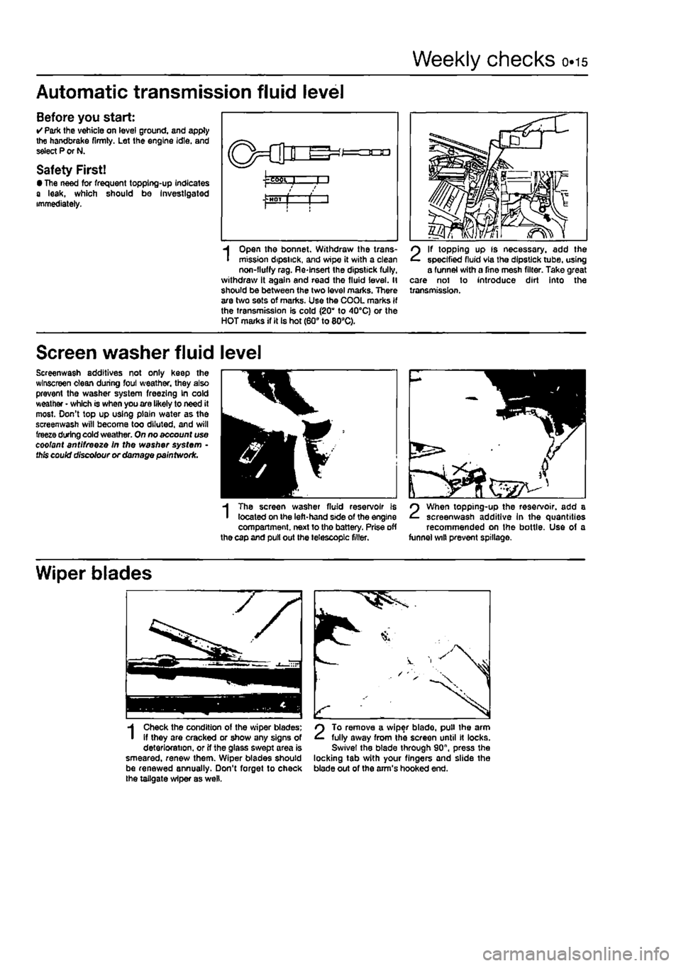
Automatic transmission fluid level
Before you start: • Park the vohicle on level ground, and apply the handbrake firmly. Let the engine idle, and select P or N.
Safety First! • The need for frequent topping-up indicates a leak, which should bo Investigated immediately.
I
Open the bonnet. Withdraw the trans-mission dipstick, and wipe it with a clean non-fluffy rag. Re-Insert the dipstick fully, withdraw it again and read the fluid level. II should be between (he two level marks. There are two sets of marks. Use the COOL marks if the transmission is cold (20" to 40°C) or the HOT marks if it Is hot (60" to 809C).
2
If topping up fs necessary, add the specified fluid via the dipstick tube, using a funnel with a fine mesh filter. Take great care nol to introduce dirt into the transmission.
Screen washer fluid level
Screenwash additives not only keep the wlnscreen clean during foul weather, they also prevent the washer system freezing kn cold weather • which is when you are likely to need it most. Don't top up using plain water as the screenwash will become too diluted, and will freeze during cold weather. On no account use coolant antifreeze In the washer system • this could discolour or damage paintwork.
3H
m
I
The screen washer fluid reservoir is located on the left-hand side of the engine compartment, next to the battery. Prise off the cap and pull out the telescopic filler.
2
When topping-up the reservoir, add a screenwash additive In the quantities recommended on the bottle. Use of a funnel wilt prevent spillage.
Wiper blades
1
Check the condition of the wiper blades; if they are cracked or show any signs of deterioration, or if the glass swept area is smeared, renew them. Wiper blades should be renewed annually. Don't forget to check the tailgate wiper as well.
2
To remove a wiper blade, pull the arm fully away from the screen until It locks. Swivel the blade through 90", press the locking tab with your fingers and slide the blade out of the arm's hooked end.
Page 28 of 225
Every 10 000 miles - petrol models ia.q
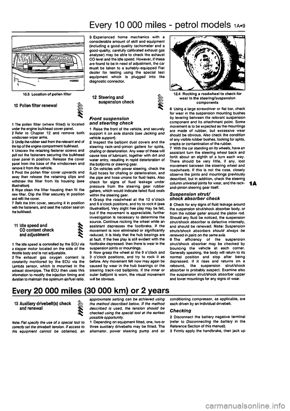
10 Pollen filter renewal
1 The pollen filter (where fitted) is located under the engine bulkhead cover panel. 2 Refer to Chapter 12 and remove both svindscreen wiper arms. 3 Unclip the rubber
seal
from the relevant end of
the
top of the engine compartment bulkhead. 4 Unscrew the retaining fastener screws and pull out the fasteners securing the bulkhead cover panel in position. Release the cover panel Irom the base of the windscreen and remove it from the vehicle. 5 Pivot the pollen filter cover upwards and away then release the retaining clips and withdraw the filter from its housing (see illustration). 6 Wipe clean the filter housing then fit the new filter. Clip the filter securely in position and refit the cover. 7 Refit the trim cover, securing it in position with Ihe fasteners, and seat the rubber seal on
the
bulkhead.
11 Idle speed and ^
CO
content check J and adjustment ^
1 The idle speed is controlled by the ECU via a stepper motor located on the side of the throttle body and is not adjustable. 2 The exhaust gas oxygen content is constantly monitored by the ECU via the Lambda sensor, which is mounted in the exhaust down pipe. The ECU then uses this information to modify the injection timing and duration to maintain the optimum air/fuel ratio.
3 Experienced home mechanics with a considerable amount of skill and equipment (including a good-quality tachometer and a good-quality, carefully calibrated exhaust gas analyser) may be able to check the exhaust CO level and the idle speed. However, if these are found to be in need of adjustment, the car must be taken to a suitably-equipped Fiat dealer for testing using the special test equipment which is plugged into the diagnostic connector.
12 Steering and ^ suspension check
front suspension and steering check 1 Raise the front of the vehicle, and securely support it on axle stands (see Jacking and
vehicle support).
2 Inspect the balljoint dust covers and the steehng rack-and-pinion gaiters for spirts, chafing or deterioration. Any wear of these will cause loss of lubricant, together with dirt and water entry, resulting in rapid deterioration of the balljoints or steering gear. 3 On vehicles with power steering, check the fluid hoses for chafing or deterioration, and the pipe and hose unions for fluid leaks. Also check for signs of fluid leakage under pressure from the steering gear rubber gaiters, which would indicate failed fluid seals within the steering gear. 4 Qrasp the roadwheel at the 12 o'clock and 6 o'clock positions, and try to rock it (see illustration). Very slight free play may be felt, but if the movement is appreciable, further investigation Is necessary to determine the source. Continue rocking the wheel while an assistant depresses the footbrake. If the movement is now eliminated or significantly reduced, it is likely that the hub bearings are at fault. If the free play is still evident with the footbrake depressed, then there is wear in the suspension joints or mountings. 5 Now grasp the wheel at the 9 o'clock and 3 o'clock positions, and try to rock it as before. Any movement felt now may again be caused by wear in the hub bearings or the steering track-rod balljoints. If the inner or outer balljoint is worn, the visual movement will be obvious.
12.4 Rocking a roadwheel to check for wear in the steering/suspension components 6 Using a large screwdriver or flat bar, check for wear in the suspension mounting bushes by levering between the relevant suspension component and its attachment point. Some movement is to be expected as the mountings are made of rubber, but excessive wear should be obvious. Also check the condition of any visible rubber bushes, looking for splits, cracks or contamination of the rubber. 7 With the car standing on its wheels, have an assistant tum the steering wheel back and forth about sn eighth of a turn each way. There should be very little, if any. lost movement between the steering wheel and roadwheels. If this is not the case, closely observe the joints and mountings previously described, but in addition, check the steering column universal joints for wear, and the rack-and-pinion steering gear itself.
Suspension strut/ shock absorber check 8 Check for any signs of fluid leakage around the suspension strut/shock absorber body, or from the rubber gaiter around the piston rod. Should any fluid be noticed, the suspension strut/shock absorber is defective internally, and should be renewed. Note: Suspension struts/shock absorbers should always be renewed in pairs on the same axle. 9 The efficiency of the suspension strut/shock absorber may be checked by bouncing the vehicle at each corner. Generally speaking, ihe body will return to its normal position and stop after being depressed. If it rises and returns on a rebound, the suspension strut/shock absorber is probably suspect. Examine also the suspension strut/shock absorber upper and lower mountings for any signs of wear.
Every 20 000 miles (30 000 km) or 2 years
13 Auxiliary drivebelt{s) check % and renewal ^
Note: Fiat specify the use of a special tool to cooectfyset the drivebelt tension. If access to ibis equipment cannot be obtained, an
approximate setting can be achieved using the method described below. If the method described is used, the tension should be checked using the special tool at the earliest possible opportunity. 1 Depending on equipment fitted, one. two or three auxiliary drivebelts may be fitted. The alternator, power steering pump and air
conditioning compressor, as applicable, are each driven by an Individual drivebelt.
Checking 2 Disconnect the battery negative terminal (refer to Disconnecting the battery in the Reference Section of this manual). 3 Firmly apply the handbrake, then jack up
Page 45 of 225
Every 10 000 miles - diesel models ib«9
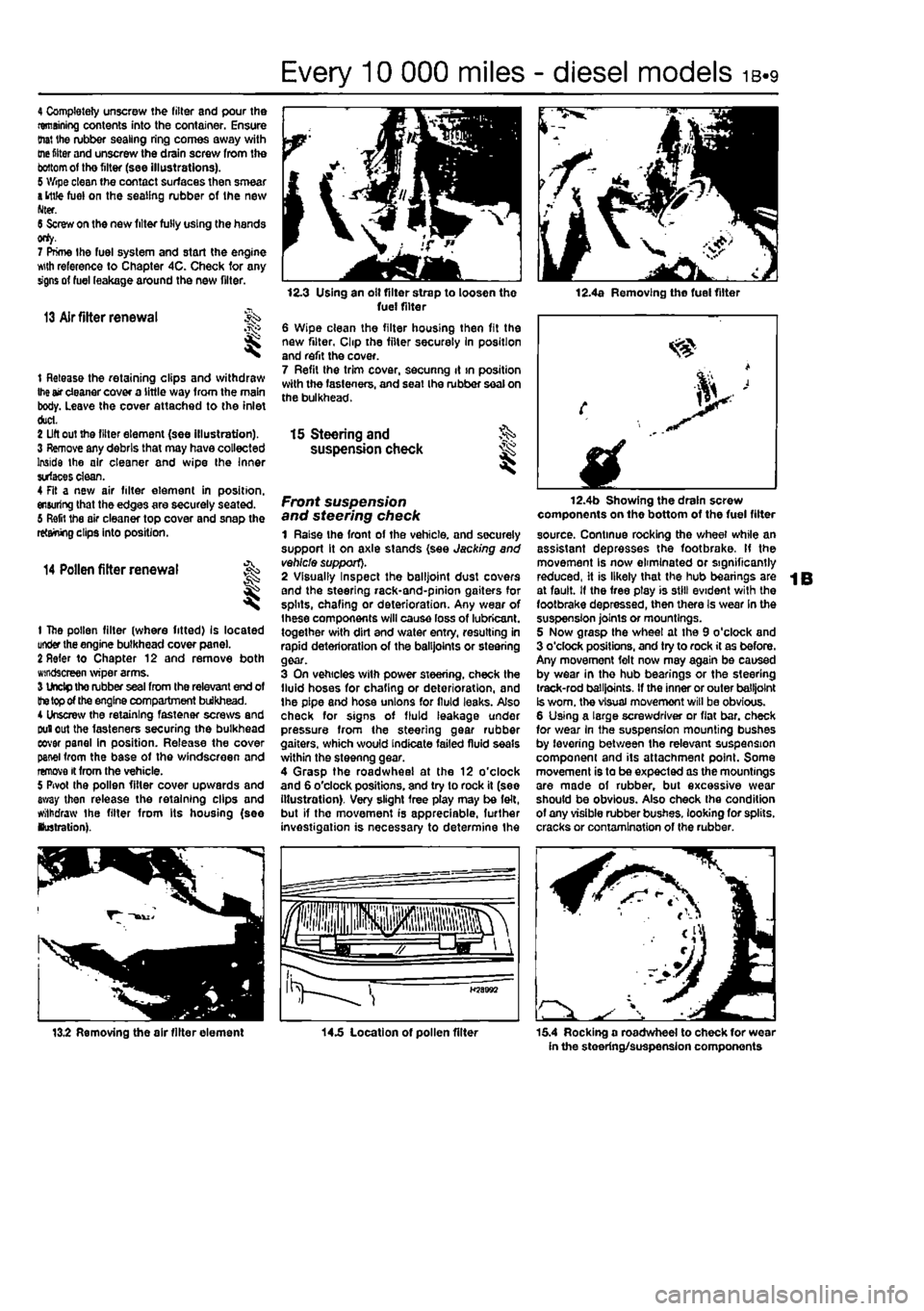
4 Completely unscrew the filter and pour the remaining contents into the container. Ensure (hat the rubber sealing ring comes away with
me
fitter and unscrew the drain screw from the
bottom
of tho filter (see illustrations). 5 Wipe clean the contact surfaces then smear
a
ittfe fuel on the sealing rubber of the new Nter. 6 Screw on the new filter fully using the hands orty. 7 Prime the fuel system and start the engine wth reference to Chapter 4C. Check for any signs of fuel leakage around the new filter.
13 Air fitter renewal
t Release the retaining clips and withdraw
Ihe
air cleaner cover a little way from the main body. Leave the cover attached to the inlet duct. 2 Lift out the filter element (see illustration). 3 Remove any debris that may have collected Inside the air cleaner and wipe the Inner surfaces clean. 4 Fit a new air filter element in position, ensuring that the edges are securely seated. 6 Refit the air cleaner top cover and snap the retaining clips into position.
14 Pollen filter renewal
t
1 The pollen filter (where fitted) Is located under the engine bulkhead cover pane). 2 Refer to Chapter 12 and remove both windscreen wiper arms. 3 Undp tho rubber seal from the relevant end of
the top
of the engine compartment bulkhead. 4 Unscrew the retaining fastener screws and Duiout the fasteners securing the bulkhead eovar panel in position. Release the cover panel from the base of the windscreen and remove it from the vehicle. 5 Pivot the pollen filter cover upwards and away then release the retaining clips and withdraw the filter from Its housing (see lustration).
12.3 Using an olt filter strap to loosen the fuel filter 6 Wipe clean the filter housing then fit the new filter, Clip the filter securely In position and refit the cover. 7 Refit the trim cover, secunng it >n position with the fasteners, and seat Ihe rubber seal on the bulkhead.
12.4a Removing the fuel filter
15 Steering and §S> suspension check ^
Front suspension and steering check 1 Raise the front of the vehicle, and securely support it on axle stands (see Jacking and vehicle support). 2 Visually Inspect the balljoint dust covers and the steering rack-and-pinion gaiters for splits, chafing or deterioration. Any wear of Ihese components will cause loss of lubricant, together with dirt and water entry, resulting in rapid deterioration of the balljoints or steering gear. 3 On vehicles with power steering, check the fluid hoses for chafing or deterioration, and the pipe and hose unions for fluid leaks. Also check for signs of fluid leakage under pressure from the steering gear rubber gaiters, which would indicate failed fluid seals within the steenng gear. 4 Grasp the roadwheel at the 12 o'clock and 6 o'clock positions, and try to rock it (see illustration). Very slight free play may be felt, but if the movement is appreciable, further investigation is necessary to determine the
fplllll iHpjiiisisps fa^aJw a LJgr >
H58B92
12.4b Showing the drain screw components on the bottom of the fuel filter source. Continue rocking the wheel while an assistant depresses the footbrake. If the movement Is now eliminated or significantly reduced, it is likely that the hub bearings are at fault. If the free ptay is still evident with the footbrake depressed, then there Is wear In the suspension joints or mountings. 5 Now grasp the wheel at the 9 o'clock and 3 o'clock positions, and try to rock it as before. Any movement felt now may again be caused by wear in the hub bearings or the steering track-rod balljoints. If the inner or outer balljoint Is worn, the visual movemont will be obvious. 6 Using a large screwdriver or flat bar. check for wear in the suspension mounting bushes by levering between the relevant suspension component and its attachment point. Some movement is to be expected as the mountings are made of rubber, but excessive wear should be obvious. Also check the condition of any visible rubber bushes, looking for splits, cracks or contamination of the rubber.
13.2 Removing the air filter element 14.5 Location of pollen filter 15.4 Rocking a roadwheel to check for wear in the steering/suspension components
Page 214 of 225
10*1
Chapter 12
Body electrical systems
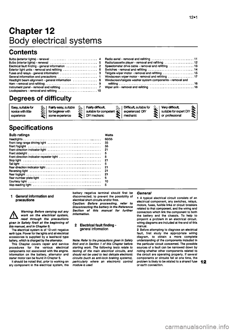
Contents
Bulbs (exterior lights) - renewal 4 Bulbs (interior lights) - renewal 5 Electrical fault finding - general information 2 Exterior light units - removal and refitting 6 Fuses and relays - general Information 3 General information and precautions 1 Headlight beam alignment • general Information 6 Horn • removal and refitting 9 Instrument panel - removal and refitting 7 Loudspeakers - removal and refitting 10
Degrees of difficulty
Radio aerial - removal and refitting 11 Radio/cassette player • removal and refitting 12 Speedometer drive cable - removal and refitting 13 Switches - removal end refitting 14 Tailgate wiper motor - removal and refitting 15 Windscreen wiper motor - removal and refitting 17 Windscreen/tailgate washer system components • removal and refitting 16 Wiper arm • removal and refitting 18
Easy,
statable for ^
novice with liffle
|| experience ^
Fairly
easy,
suitable for beginner with ^ some experience ^
Fabtycffficiit,
suitable
for competent ^
DIY
mechanic ^
Difficult, suitable for
^ experienced DIY JR mechanic
Very difficult,
A,
suitable
for
expert DIY
Sj or professional ^
Specifications
Bulb ratings Watts Headlights 60/55 Front long range driving light 55 Front fogllght 55 Front direction Indicator light 21 Front sidelight 5 Front direction indicator repeater light 5 Stop light 21 Tall light 5 Rear direction indicator light 21 Reversing light 21 near fogllght 21 Hear number plate light 5 Courtesy light 10 Map reading light 5
1 Genera! information and precautions
A
Warning: fie/Ore carrying out any work on the electrical system, read through the precautions given in Safety first! at the beginning of this manual, and in Chapter 8. The electrical system is of 12-volt negative earth type. Power for the lights and all electrical accessories is supplied by a lead/acid type battery, which is charged by the alternator. This Chapter covers repair and service procedures for the various electrical components not associated with the engine. Information on the battery, alternator and starter motor can be found in Chapter 5. It should be noted that, prior to working on any component In the electrical system, the
battery negative terminal should first be disconnected, to prevent the possibility of electrical short-circuits and/or fires. Caution: Before proceeding, refer to Disconnecting the battery In the Reference Section of this manual for further information.
2 Electrical fault finding-general information
Note: Refer to the precautions given In Safety first! and in Section 1 of this Chapter before starting work. The following tests relate to testing ot the main electrical circuits, and should not be used to test delicate electronic circuits (such as antHock braking systems), particularly where an electronic con fro/ module is used.
General 1 A typical electrical circuit consists of an electrical component, any switches, relays, motors, fuses, fusible links or circuit breakers related to that component, and the wiring and connectors which link the component to both the battery and the chassis. To help to pinpoint a problem in an electrical circuit, wiring diagrams are Included at the end of this manual. 2 Before attempting to diagnose an electrical fault, first study the appropriate wiring diagram, to obtain a more complete understanding of the components included In the particular circuit concerned. The possible sources of a fault can be narrowed down by noting whether other components related to the circuit are operating properly. If several components or circuits fait at one time, the problem Is likely to be related to a shared fuse or earth connection.
Page 215 of 225
12*2 Body electrical systems
3 Electrical problems usually stem from simple causes, such as loose or corroded connections, a faulty earth connection, a blown fuse, a melted lusible link, or a fautty relay {refer to Section 3 for details of testing relays). Visually inspect the condition of all (uses, wires and connections in a problem circuit before testing the components. Use the wiring diagrams lo determine which terminal connections will need to be checked, in order to pinpoint the trouble-spot. 4 The basic tools required for electrical fault-finding include a circuit tester or voltmeter (a 12-volt bulb with a set of lest leads can also be used for certain tests}; a self-powered test light (sometimes known as a continuity tester); an ohmmeter (to measure resistance): a battery and set of tesi leads: and a lumper wire, preferably with u circuit breaker or fuse incorporated, which can be used to bypass susoect wires or electrical components. Before attempting to locate a problem with tost instruments, use the wiring diagram to determine where to make the connections. 5 To find the source of an intermittent wiring fault (usually due to a poor or dirty connection, or damaged wiring Insulation), a wiggle test can be performed on the wiring. This involves wiggling the wiring by hand, to see if tha fault occurs as the wiring Is moved. It should be possible to narrow down the source of the fault to a particular section of wiring. This method of testing can be used in conjunction with any of the tests descnbed in the following sub-Sections. 6 Apart from problems due to poor connections, two basic types of fault can occur in an electrical circuit - open-circuit, or short-circuit. 7 Open-circuit faults are caused by a break somewhere in the circuit, which prevents current from flowing. An open-circuit fault will prevent a component from working, but will not cause the relevant circuit fuse to blow 8 Short-circuit faults are caused by a shod somewhere in the circuit, which allows Die current flowing In the circuit to escape along an alternative route, usually to earth. Short-circuit faults are normally caused by a breakdown in wiring insulation, which allows a feed wire to touch either another wire, or an earthed component such as the bodysheli. A short-circuit fault will normally cause the relevant circuit fuse to blow.
Finding an open-circuit 9 To check for an opon-circuit, connect one lead of a circuit tester or voltmoter to either the negative battery terminal or a known good earth. 10 Connect the other lead to a connector in the circuit being tested, preferably nearest to the batter/ or luse. 11 Switch on the circuit, bearing In mind that some circuits are live only when tho ignition switch is moved to a particular position. 12 If voltage is present (Indicated either by
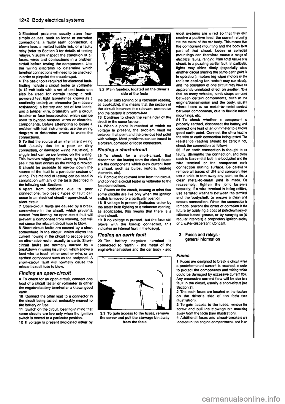
3.2 Main fuse box, located on the driver's side of the facie the toster bulb lighting or a voltmeter reading, as applicable), this means that tho section of Ihe circuit between the relevant connector and the battery is problem-free. 13 Continue to check the remainder ot the circuit in the same fashion. 14 When a point is reached at which no voltage Is present, the problem must lie between that point and the previous test point with voltage. Most problems can be traced to a broken, corroded or loose connection.
Finding a short-circuit 15 To check for a short-circuit, first disconnect the load(s) from the circuit (loads are the components which draw current from a circuit, such as bulbs, motors, heating elements, etc). 16 Remove the relevant luse Irom the circuit, and connect a circuit tester or voltmeter to the luse connections. 17 Switch on the circuit, beanng in mind that some circuits are live only when the ignition switch is moved to a particular position. 18 If voltage is present (indicated either by the tester bulb lighting or a voltmeter reading, as applicable), this means that there Is a short-circuit. 19 If no voltage is present, but the fuse still blows with the load(s) connected, this indicates an internal fault in the load(s).
Finding an earth fault 20 The battery negative terminal Is connected to 'earth' - the metal of the engine/transmission and the car body - and
I
IK
J 3.3 To gain access to the fuses, remove the screw and pull the stowage bin away from the facia
most systems are wired so that they only receive a positive feed, the current returning via the metal of Ihe car body. This means that the component mounting and the body form part of that circuit. Loose or corroded mountings can therefore cause a range of electrical faults, ranging from total failure ot a circuit, to a puzzling partial fault. In particular, lights may shine dimly (especially when another circuit sharing the same earth port In operation), motors (eg wiper motors v Ihe radiator cooling fan motor) may run slowly, and Ihe operation of one circuit may have an apparently-unrelated effect on another. Ncie that on many vehicles, earth straps axe uses between certain components, such as the engine/transmission and the body, usually whore there is no metal-to-metal contact between components, due to flexible rubber mountings, etc. 21 To check whether a component $ properly earthed, disconnect Ihe battery, and connect one lead of an ohmmeter to a kwwi good earth point. Connect the other lead to the wire or earth connection being tested. Tha resistance reading should be zero; if not. check the connection as follows. 22 If an earth connection Is thought to be faulty, dismantle the connection, and clean pack to bare metal both the bodysheli and ite wire terminal or the component earth connection mating surface. Be careful to remove all traces of dirt and corrosion, then use a knife to trim away any palm, so thai a clean metal-to-metal joint Is mads. On reassemoly, tighten the joint fasteners securely: if a wire terminal Is being refitted, use serrated washers between tho terminal and the bodysheli. to ensure a clean and secure connection. When the connection is remade, prevent the onset ot corrosion in the future by applying a coat of petroleum idly
or
stlicone-based grease, or by spraying on (a: regular intervals} a proprietary ignition eoater, or a water-aispersant lubneant.
3 Fuses and relays -general information
Fuses 1 Fuses are designod to break a circuit when a predetermined current is reached, in order to protect the components and wiring wttioh could be damaged by excessive current How. Any excessive current flow will be due to a fault in the circuit, usually a short-circuit (see Section 2). 2 The main fuses are located in the fusefcox on the driver's side of the facia (see illustration). 3 To gain access to the fuses, remove tne screw and pull the stowage bin moulding away from the facia (see illustration). 4 Additional fuses and circuit-breakers are located In the engine compartment, and in an
Page 216 of 225
Body electrical systems 12*3
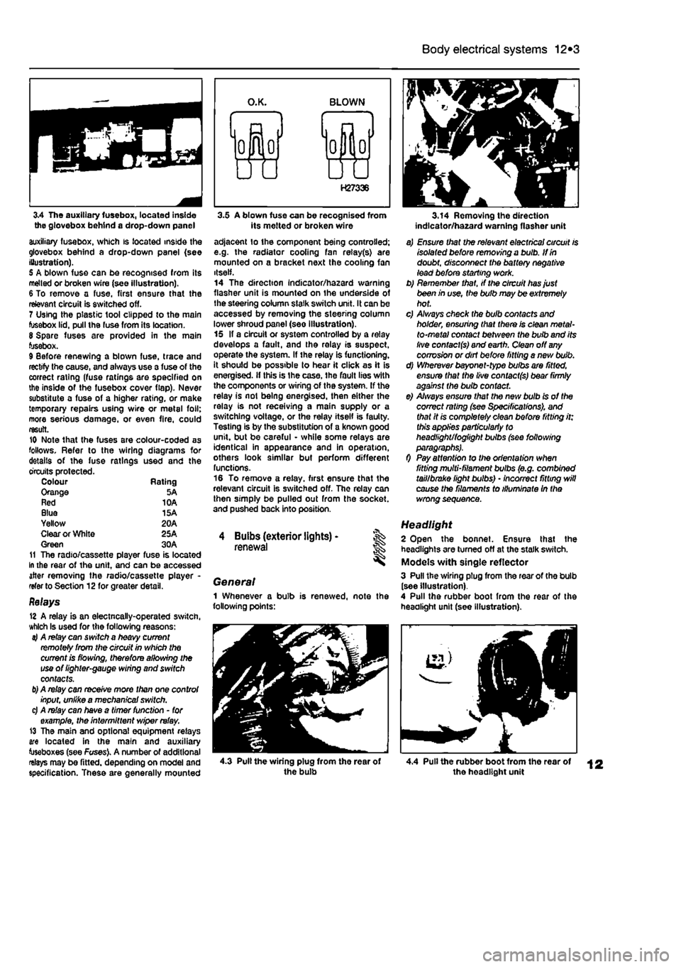
3.4 The auxiliary fusebox, located inside the glovebox behind a drop-down panel auxiliary fusebox, which is located inside the glovebox behind a drop-down panel (see Illustration). 5 A blown fuse can be recognised from its melted or broken wire (see illustration). 6 To remove a fuse, first ensure that the relevant circuit is switched off. 7 Using the plastic tool clipped to the main fusebox lid, pull the fuse from its location. 8 Spare fuses are provided in the main fusebox. 9 Before renewing a blown fuse, trace and rectify the cause, and always use a fuse of the correct rating (fuse ratings are specified on the inside of the fusebox cover flap). Never substitute a fuse of a higher rating, or make temporary repairs using wire or metal foil; more serious damage, or even fire, could result. 10 Note that the fuses are colour-coded as follows. Refer to the wiring diagrams for details of the fuse ratings used and the circuits protected. Colour Rating Orange 5A Red 10A Blue 15A Yellow 20A Clear or White 25A Green 30A 11 The radio/cassette player fuse is located In the rear of the unit, and can be accessed after removing the radio/cassette player -refer to Section 12for greater detail.
Relays 12 A relay is an electncally-operated switch, which Is used for the following reasons: 4 A relay can switch a heavy current remotely from the circuit in which the current is flowing, therefore allowing the use of lighter-gauge wiring and switch contacts.
b)
A relay can receive more than one control input, unlike a mechanical switch. c) A relay can have a timer function - for example, the intermittent wiper relay. 13 The main and optional equipment relays are located in the main and auxiliary toseboxes (see Fuses). A number of additional relays may be fitted, depending on model and specification. These are generally mounted
3.5 A blown fuse can be recognised from its melted or broken wire adjacent lo the component being controlled; e.g. the radiator cooling fan relay(s) are mounted on a bracket next the cooling fan itself. 14 The direction Indicator/hazard warning flasher unit is mounted on the underside of the steering column slalk switch unit. It can be accessed by removing the steering column lower shroud panel (see illustration). 15 If a circuit or system controlled by a relay develops a fault, and the relay is suspect, operate the system. If the relay is functioning, it should be possible to hear it click as it is energised, if this is Ihe case, the fault lies with the components or wiring of the system. If the relay is not being energised, then either the relay is not receiving a main supply or a switching voltage, or the relay itself is faulty. Testing is by the substitution of a known good unit, but be careful - while some relays are identical in appearance and in operation, others look similar but perform different functions. 16 To remove a relay, first ensure that the relevant circuit is switched off. The relay can then simply be pulled out from the socket, and pushed back into position.
4 Buibs (exterior lights) -renewal
General 1 Whenever a bulb is renewed, note the following points:
3.14 Removing the direction indlcator/ha2ard warning flasher unit
a) Ensure that the relevant electrical circuit is isolated before removing a bulb. If in doubt, disconnect the battery negative lead before starting work. b) Remember that, if the circuit has just been in use, the bulb may be extremely hot. c) A/ways check the bulb contacts and holder, ensuring that there is clean metal-to-metal contact between the bulb and its live contacts) and earth. Clean off
any
corrosion or dirt before fitting a nevt bulb. d) Wherever bayonet-type bulbs are fitted, ensure that the live contacts) bear firmly against the bulb contact. e) Always ensure that the new bulb is of the correct rating (see Specifications), and that it is completely clean before fitting it; this applies particularly to headlight/foglight bulbs (see following
0 Pay attention to the orientation when fitting multi-filament bulbs (e.g. combined tail/brake light bulbs) • incorrect fitting will cause the filaments to illuminate In the wrong sequence.
Headlight 2 Open the bonnet. Ensure that the headlights are turned off at the stalk switch. Models with single reflector 3 Pull the wiring plug from the rear of the bulb (see illustration). 4 Pull the rubber boot from the rear of the headlight unit (see Illustration).
4.3 Pull the wiring plug from the rear of the bulb 4.4 Pull the rubber boot from the rear of the headlight unit
Page 223 of 225
12*10 Body electrical systems
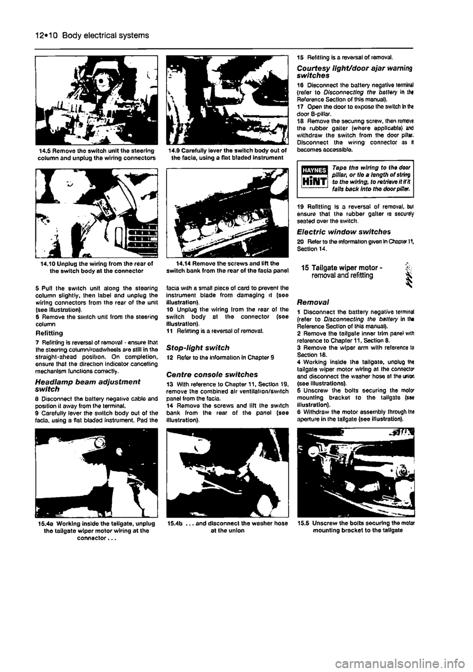
14.5 Remove the switch unit the steering column and unplug the wiring connectors 14.9 Carefully lever the switch body out of the facia, using a flat btaded instrument
14.10 Unplug the wiring from tho rear of the switch body at the connector
5 Pull the switch unit along ihe steering column slightly, then label and unplug the wiring connectors from the rear of the unit (sec Illustration). 6 Remove the switch unit from the steering column Refitting 7 Refitting is reversal of removal • ensure that the steering column/roadwheels are still in the straight-ahead position. On completion, ensure that the direction indicator cancelling mechanism lunations correctly.
Headlamp beam adjustment switch 8 Disconnect the battery negative cable and position il away from the terminal. 9 Carefully lever the switch body out of the facia, using a flat bladed instrument. Pad the
15 Refitting is a reversal of removal. Courtesy light/door ajar warning switches 16 Disconnect the battery negative terminal (refer to Disconnecting the battery in thf Reference Section of this manual). 17 Open the door to expose the switch
in
the door 8-plHar. 18 Remove the secunng screw, then remove the rubber gaiter (where applicable) ant) withdraw the switch from the door pillar. Disconnect the wiring connector as tl becomes accessible.
Tape the wiring to the
door
i m | pillar, or tie a length of
string
HlNTi to the wiring, to retrieve itttit falls back Into the door pillar.
14.14 Remove the screws and lift the switch bank from the rear of the facia panel
facia with a small piece of card to prevent the Instrument blade from damaging it (see illustration). 10 Unplug the wiring Irom Ihe rear of the switch body at Ihe connector (see illustration). 11 Refitting is a reversal of removal
Stop-light switch 12 Refer to the information in Chapter 9
Centre console switches 13 With reference to Chapter 11, Section 19, remove the combined air ventilation/switch panel from the facia. 14 Remove the screws and lift Ihe switch bank from Ihe rear of the panel (see illustration),
19 Refitting Is a reversal of removal, but ensure that the rubber gaiter is securely seated over the switch.
Electric window switches 20 Refer to the information given
In
Chapter It, Section 14.
15 Tailgate wiper motor - & removal and refitting ^
Removal 1 Disconnect the battery negative terminal (refer to Disconnecting the battery in the Reference Section of this manual), 2 Remove the tailgate inner trim panel with reference to Chapter 11, Section 8. 3 Remove the wiper arm with reference to Section 18. 4 Working inside the tailgate, unplug tlx tailgate wiper motor wiring at Ihe connector and disconnect the washer hose at
1he
union (see illustrations). 6 Unscrew the bolts securing the motor mounting bracket to the tailgate (see illustration). 6 Withdraw the motor assembly through tte aperture in the tailgate (see illustration).
15.4a Working inside the tellgate, unplug tho tailgate wiper motor wiring at the connector...
. and disconnect tho washer hose at the union 15.5 Unscrew the bolts securing the motor mounting bracket to the tailgate
Page 224 of 225
Body electrical systems 12*11
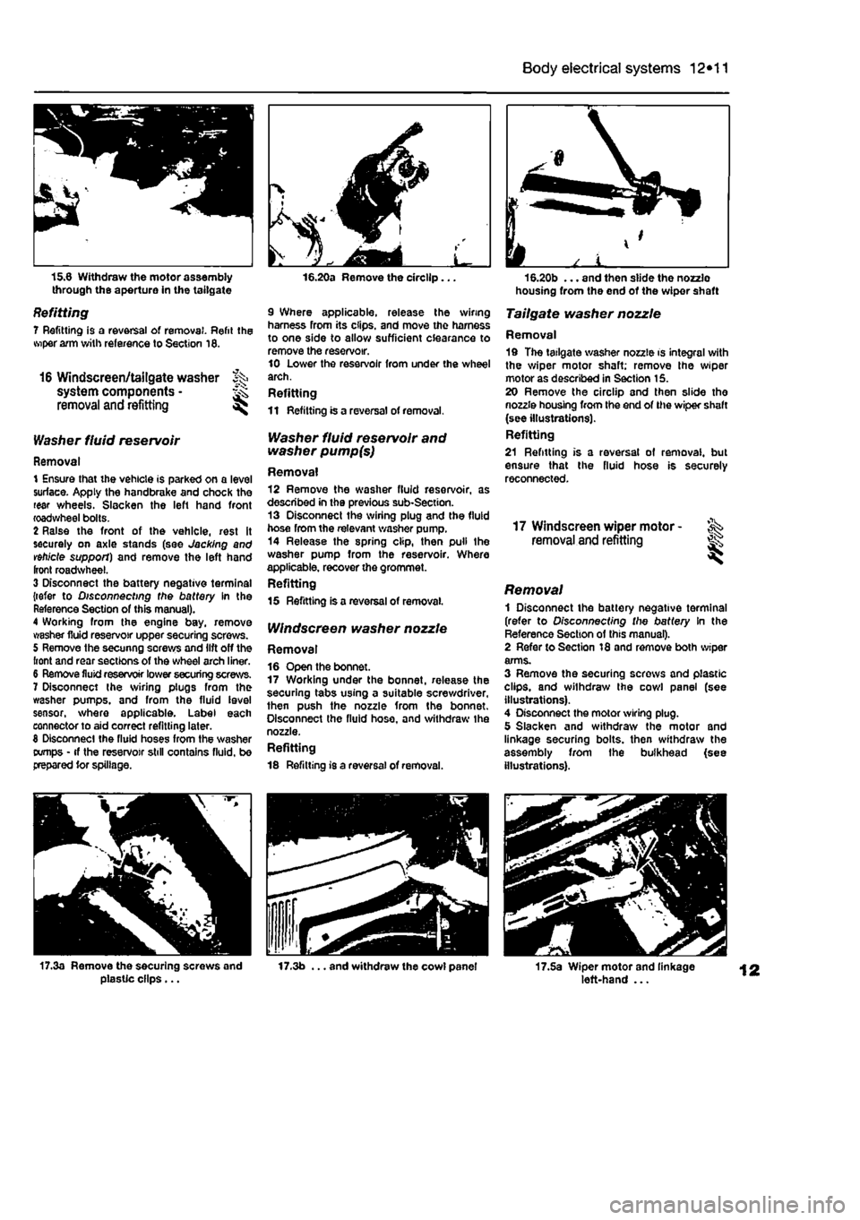
15.6 Withdraw the motor assembly through the aperture in the tailgate
Refitting 7 Refitting is a reversal of removal. Refit the wiper arm with reference to Section 16.
16 Windscreen/tailgate washer % system components • ^ removal and refitting ^
Washer fluid reservoir
Removal 1 Ensure that the vehicle is parked on a level surface. Apply the handbrake and chock the rear wheels. Slacken the left hand front roadwheel bolts. 2 Raise the front of the vehicle, rest it securely on axle stands (see Jacking and vehicle support) and remove the left hand front roadwheel. 3 Disconnect the battery negative terminal {refer to Disconnecting the battery In the Reference Section of this manual). 4 Working from the engine bay, remove washer fluid reservoir upper securing screws. 5 Remove the secunng screws and lift off the front and rear sections of the wheel arch liner. 6 Remove fluid reservoir lower securing screws. 7 Disconnect the sviring plugs from the washer pumps, and from the fluid level sensor, where applicable. Label each connector to aid correct refitting later. 8 Disconnect the fluid hoses from the washer tx/mps • if the reservoir still contains fluid, be prepared tor spillage.
16.20a Remove the circllp...
9 Where applicable, release the wiring harness from its clips, and move the harness to one side to allow sufficient clearance to remove the reservoir. 10 Lower the reservoir from under the wheel arch. Refitting 11 Refitting is a reversal of removal.
Washer fluid reservoir and washer pump(s)
Removal 12 Remove the washer fluid reservoir, as described in the previous sub-Section. 13 Disconnect the wiring plug and the fluid hose from the relevant washer pump. 14 Release the spring clip, then pull the washer pump from the reservoir. Where applicable, recover the grommet. Refitting 15 Refitting is a reversal of removal.
IV/nctecreen washer nozzle
Removal 16 Open the bonnet. 17 Working under the bonnet, release the securing tabs using a suitable screwdriver, then push the nozzle from the bonnet. Disconnect the fluid hose, and withdraw the nozzle. Refitting 18 Refitting is a reversal of removal.
housing from the end of the wiper shaft
Tailgate washer nozzle
Removal 19 The tailgate washer nozzle is integral with the wiper motor shaft; remove the wiper motor as described in Section 15. 20 Remove the circllp and then slide the nozzle housing from the end of the wiper shaft (see illustrations). Refitting 21 Refitting is a reversal of removal, but ensure that the fluid hose is securely reconnected.
17 Windscreen wiper motor -removal and refitting ^
Removal 1 Disconnect the battery negative terminal (refer to Disconnecting the battery In the Reference Section of this manual). 2 Refer to Section 18 and remove both wiper arms. 3 Remove the securing screws and plastic clips, and withdraw the cowl panel (see illustrations). 4 Disconnect the motor wiring plug. 5 Slacken and withdraw the motor and linkage securing bolts, then withdraw the assembly from the bulkhead (see illustrations).
17.3a Remove the securing screws and plasUc clips... 17.3b ... and withdraw the cowl panel 17.5a Wiper motor and linkage left-hand ...