Lock FIAT PUNTO 1997 176 / 1.G Workshop Manual
[x] Cancel search | Manufacturer: FIAT, Model Year: 1997, Model line: PUNTO, Model: FIAT PUNTO 1997 176 / 1.GPages: 225, PDF Size: 18.54 MB
Page 219 of 225

12*6 Body electrical systems
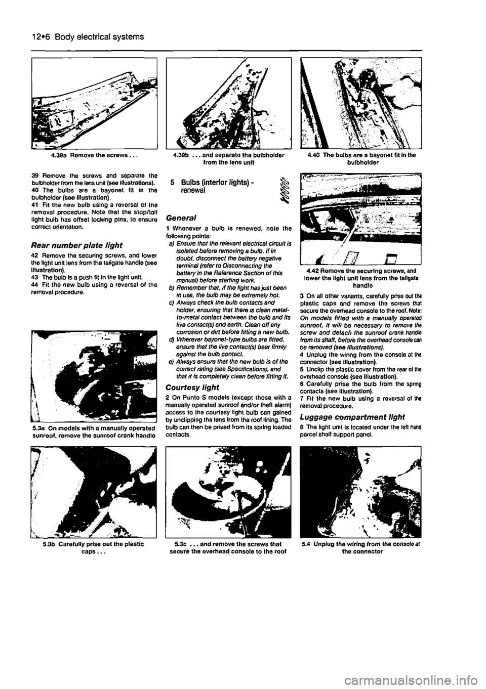
4.39a Remove the screws...
39 Remove the screws and separate the bulbholder from the lens unit (see Illustrations). 40 The bulbs are a bayonet (it in the bulbholder (s&e Illustration), 41 Fit the new bulb using a rovorsal of the removal procedure. Note that the stop/tall light bulb has offset locking pins, to ensure correct orientation.
Rear number plate light 42 Remove the securing screws, and lower the light unit lens from the tailgate handle (see Illustration), 43 The bulb Is a push fit In the light unit. 44 Fit the new bulb using a reversal of the removal procedure.
5.3a On models with a manually oporated sunroof, remove the sunroof crank handle
5.3b Carefully prise out the pfestic caps...
from the lens unit
5 Bulbs (interior lights) -renewal
General 1 Whenever a bulb is renewed, note Ihe following points: a) Ensure that the relevant electrical circuit is Isolated before removing a bulb. If
In
doubt, disconnect the battery negative terminal (refer to Disconnecting the battery In the Reference Section of this manual) before starting work. b) Remember that, if the light has just been in use, the bulb may be extremely hot. c) Always check the bulb contacts and holder, ensuring that there is clean metal-to-metal contact between the bulb and its live contacts) and earth, dean off any corrosion or dirt before fitting a new bulb. d) Wherever bayonet-type bulbs are fitted, ensure that the live contact(s) bear (irmly against the bulb contact. e) Always ensure that the new bulb is of the correct rating (see Specifications), and that it Is completely clean before fitting it.
Courtesy light 2 On Punto S models (except those with a manually operated sunroof end/or theft alarm) access to the courtesy light bulb can gained by unclipping the lens from the roof lining. The bulb can then be prised from its spring loaded contacts.
5.3c ... and remove the screws that secure the overhead console to the roof
buibhoidai
/ ' fl B 4.42 Remove the securing screws, and lower the light unit lens from the tailgate handle 3 On all other variants, carefully prise out the plastic caps and remove the screws that secure the overhead console lo the roof. Note: On models fitted with a manually operator sunroof, it will be necessary to remove
the
screw and detach the sunroof crank
handle
from its shaft, before the overhead console can be removed (see illustrations). A Unplug Ihe wiring from the console at the connector (see illustration). 5 Unciip the plastic cover from the rear ol the overhead console (see illustration). 6 Carefully prise the bulb from the spring contacts (see Illustration). 7 Fit the new bulb using a reversal of the removal procedure.
Luggage compartment light 8 The light unit is located under 1he left hand parcel shelf support panel.
5.4 Unplug Ihe wiring from (he console at the connector
Page 220 of 225

Body electrical systems 12*7
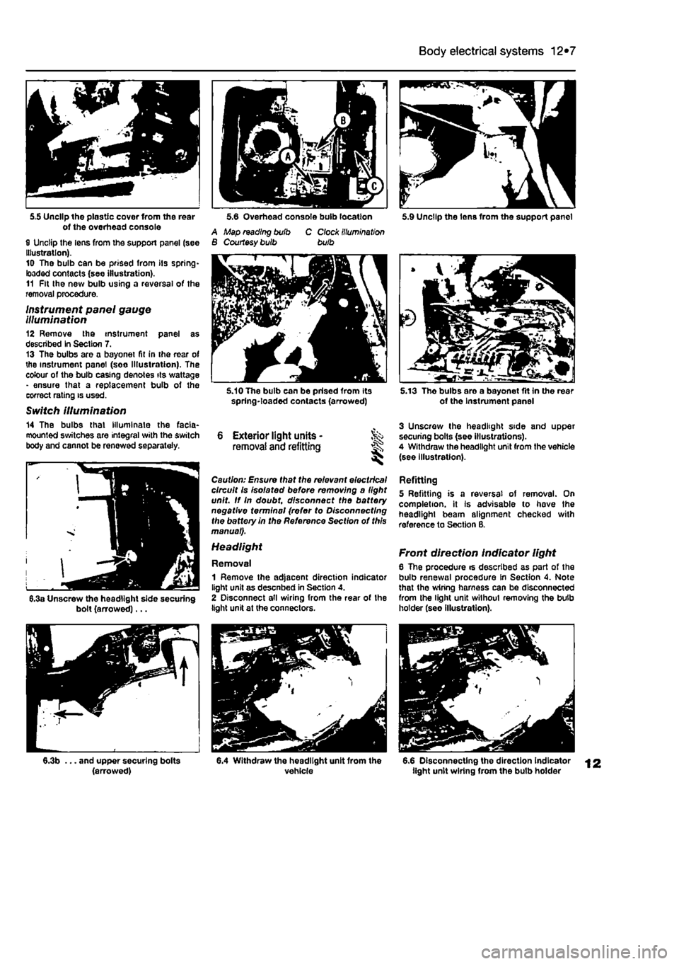
5,5 Unclip the plastic cover from the rear of the overhead console 0 Unclip the lens from the support panel (see Illustration). 10 The bulb can be prised from its spring-loaded contacts (see illustration). 11 Fit the new bulb using a reversal of the removal procedure.
Instrument panel gauge Illumination 12 Remove the instrument panel as described In Section 7. 13 The bulbs are a bayonet fit in the rear of the instrument panel (see Illustration). The colour of the bulb casing denotes its wattage - ensure that a replacement bulb of the correct rating is used.
Switch illumination 14 The bulbs that Illuminate the facia-mounted switches are integral with the switch body and cannot be renewed separately.
5.6 Overhead console bulb location 5.9 Unclip the Ions from the support panel A Map reading bulb B Courtesy bulb C Clock illumination bulb
6.3a Unscrew the headlight side securing bolt (arrowed)...
5.10 The bulb can be prised from its spring-loaded contacts (arrowed)
6 Exterior light units • removal and refitting ^ ^
Caution: Ensure that the relevant electrical circuit is isolated be/ore removing a light unit. If In doubt, disconnect the battery negative terminal (refer to Disconnecting the battery in the Reference Section of this manual).
1 Remove the adjacent direction indicator light unit as descnbed in Section 4. 2 Disconnect all wiring from the rear of the light unit at the connectors.
5.13 Tho bulbs are a bayonet fit in the rear of the instrument panel
3 Unscrew the headlight side and upper securing bolts (see illustrations). 4 Withdraw the headlight unit from the vehicle (see illustration).
Refitting 5 Refitting is a reversal of removal. On completion, it Is advisable to hove the headlight beam alignment checked with reference to Section B.
Front direction indicator light 6 The procedure is described as part of the bulb renewal procedure In Section 4. Note that the wiring harness can be disconnected from the light unit without removing the bulb holder (seo illustration).
6.3b ... and upper securing bolts (arrowed) 6.4 Withdraw the headlight unit from the vehicle 6.6 Disconnecting the direction indicator light unit wiring from the bulb holder