Rear wash FIAT PUNTO 1997 176 / 1.G Workshop Manual
[x] Cancel search | Manufacturer: FIAT, Model Year: 1997, Model line: PUNTO, Model: FIAT PUNTO 1997 176 / 1.GPages: 225, PDF Size: 18.54 MB
Page 10 of 225
Roadside repairs 0.9
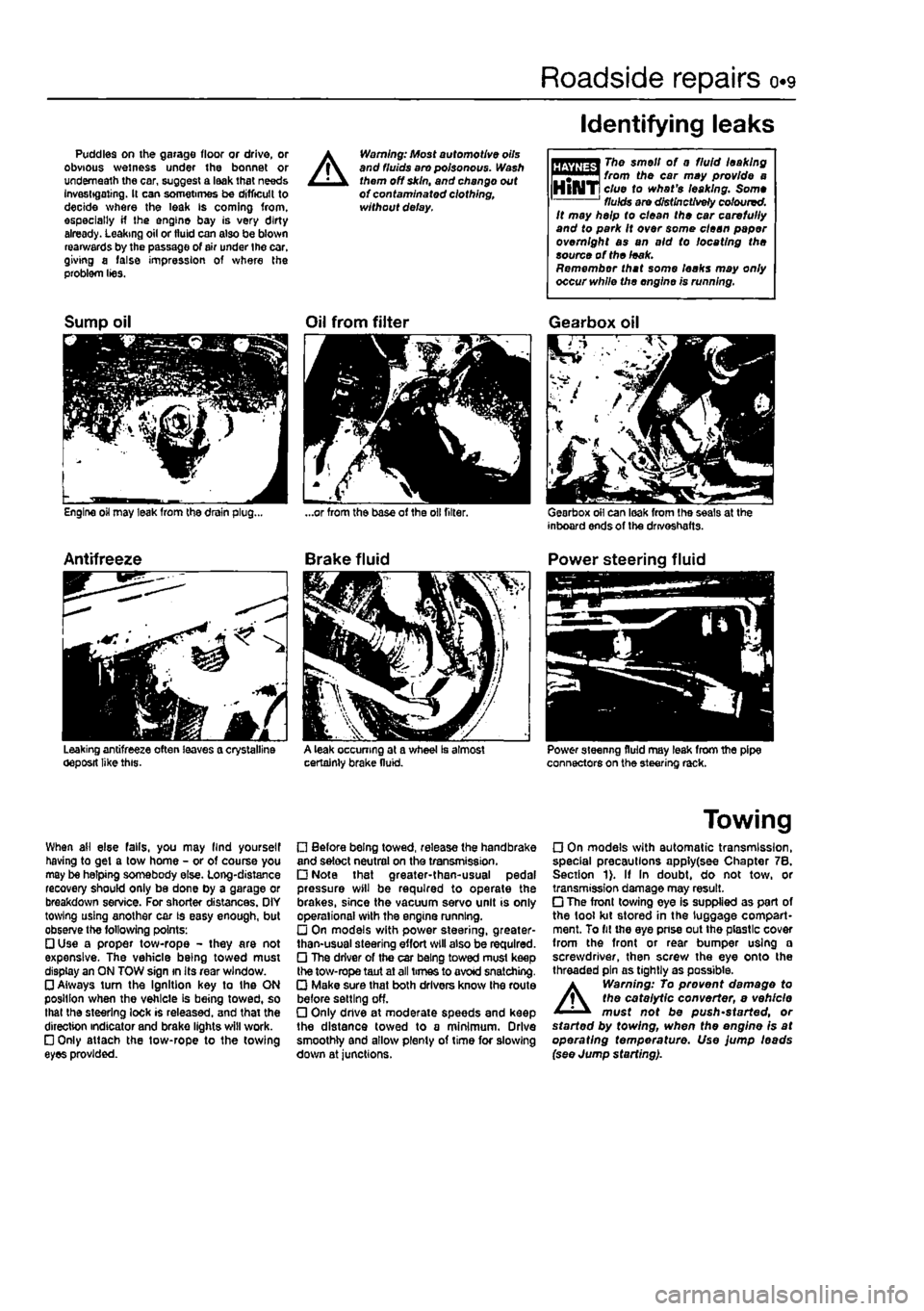
Puddles on the garage floor or drive, or obvious wetness under the bonnet or underneath the car, suggest a leak that needs Investigating. It can sometimes be difficult to decide where the leak is coming from, especially if the engine bay is very dirty already. Leaking oil or fluid can also be blown rearwards by the passage of air under the car, giving a false impression of where the problem lies.
A
Warning: Most automotive oils and fluids aro poisonous. Wash them off skin, and change out of contaminated clothing, without delay.
Identifying leaks
The smell of 0 fluid leaking from the car may provide a clue to what's leaking. Some fluids are distinctively coloured. It may help to clean the car carefully and to park It over some clean paper overnight as an aid to locating the source of the leak. Remember that some leaks may only occur while the engine is running.
Sump oil
Engine oil may leak from the drain plug...
Antifreeze
Leaking antifreeze often leaves a crystalline oeposit like this.
Oil from filter
A leak occurring at a wheel Is almost certainly brake fluid.
Gearbox oil
Gearbox oil can leak from the seals at the inboard ends of the drivoshafts.
Power steering fluid
Power steering fluid may leak from the pipe connectors on the steering rack.
When ail else falls, you may llnd yourself having to get a tow home - or of course you may be helping somebody else. Long-distance recovery should only be done by a garage or breakdown service. For shorter distances. OIY towing using another car is easy enough, but observe the following points: • Use a proper tow-rope - they are not expensive. The vehicle being towed must display an ON TOW sign in its rear window. • Always turn the Ignition key to the ON position when the vehicle is being towed, so that the steering lock is released, and that the direction indicator and brake lights will work. • Only attach the tow-rope to the towing eyes provided.
• Before being towed, release the handbrake and select neutral on the transmission. • Note that greater-then-usual pedal pressure will be required to operate the brakes, since the vacuum servo unit is only operational with the engine running. • On models with power steering, greater-than-usual steering effort will also be required. • The driver of the car being towed must keep the tow-rope taut at all times to avoid snatching. • Make sure that both drivers know the route before setting off. • Only dnve at moderate speeds and keep the distance towed to a minimum. Drive smoothly and allow plenty of time for slowing down at junctions.
Towing
• On models with automatic transmission, special precautions apply(see Chapter 7B. Section 1). If In doubt, do not tow, or transmission damage may result. • The front towing eye is supplied as part of the tool kit stored in the luggage compart-ment. To fit the eye pnse out the plastic cover from the front or rear bumper using a screwdriver, then screw the eye onto the threaded pin as tightly as possible.
A
Warning: To prevent damage to the catalytic converter, e vehicle must not be push'started, or started by towing, when the engine is at operating temperature. Use jump leads (see Jump starting).
Page 24 of 225
Component location - petrol models 1A.5
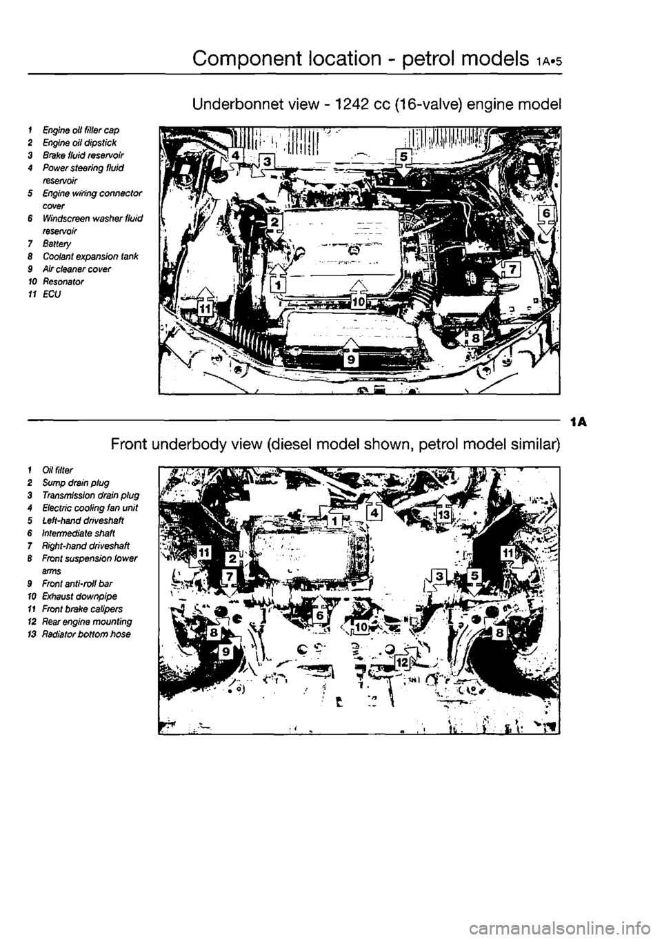
Underbonnet view - 1242 cc (16-valve) engine model
1
Engine
olt filler
cap
2
Engine
oil dipstick 3
Brake
fluid
reservoir
4
Power
steering fluid reservoir 5
Engine
wiring connector cover 6
Windscreen
washer
fluid
reservoir 7 Battery 8
Coolant
expansion
tank
9 Air cleaner
cover
10 Resonator 11 ECU
1
Oil filter
2
Sump
drain plug 3
Transmission
drain plug A
Electric
cooling Ian unit 5
Left-hand driveshaft
6
Intermediate shaft
7
Right-hand driveshaft
B
Front
suspension lower arms 9
Front
anti-roll
bar
10
Exhaust
downpipe 11
Front
brake calipers (2
Rear engine
mounting IS Radiator bottom hose
Front underbody view (diesel model shown, petrol model similar)
Page 40 of 225
ib-4 Component location - diesel models
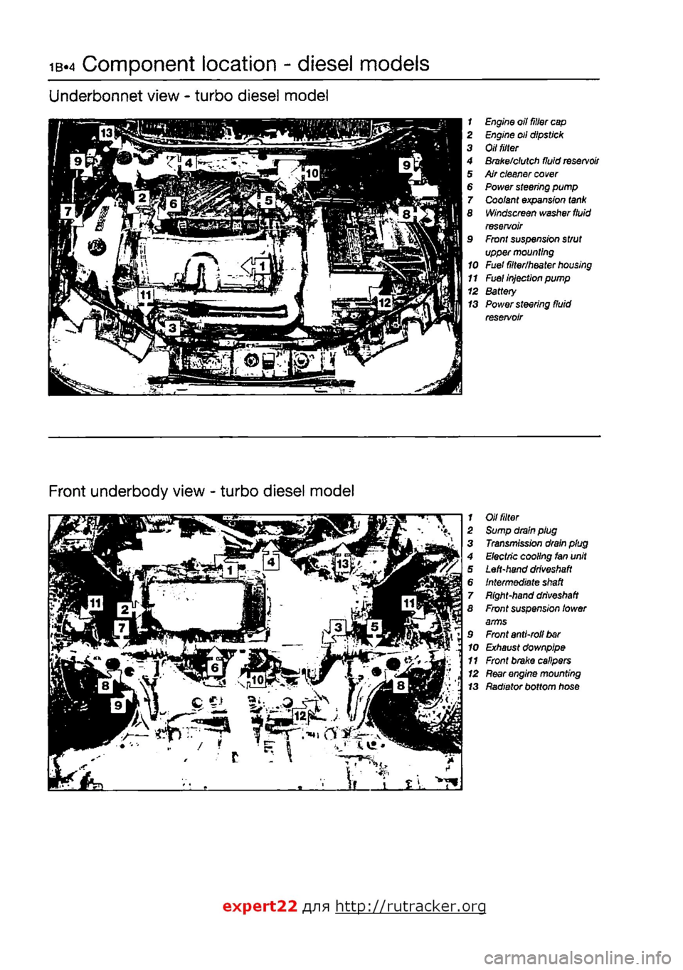
Underbonnet view - turbo diesel model
1 Engine oil filter
cap
2 Engine oil dipstick 3 Oil
tilter
4 Brake/clutch fluid
reservoir
5 Air cleaner
cover
6 Power steering pump 7 Coolant expansion
tank
8 Windscreen washer
fluid
reservoir 9 Front suspension strut upper mounting 10 Fuel filter/heater
housing
11
Fuel
injection pump 12 Battery 13 Power steering fluid reservoir
Front underbody view - turbo diesel model
1 Oil
fitter
2 Sump drain plug 3 Transmission drain plug 4 Electric cooling fan unit 5 Left-hand
driveshaft
6 Intermediate
shaft
7 Bight-hand
driveshaft
8 Front suspension lower arms 9 Front anti-roll
bar
10 Exhaust downpipe 11 Front brake calipers 12
Rear
engine mounting 13 Radiator bottom hose
expert22 fl/ia http://rutracker.org
Page 56 of 225
2A*10 SOHC (8-valve) petrol engine in-car repair procedures
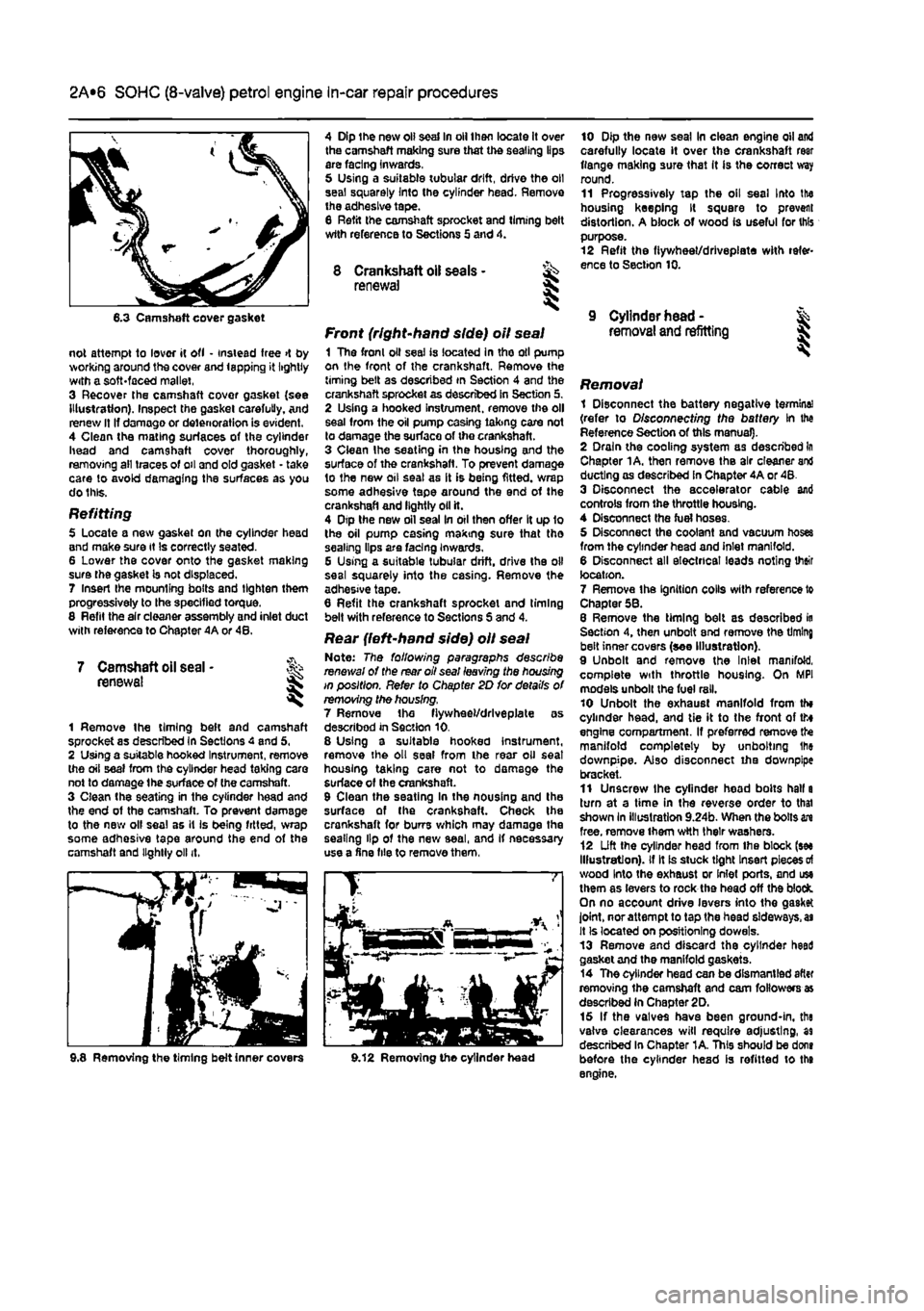
6.3 Camshaft cover gasket
not attempt to lover it ofl • instead free >t by working around the cover and lapping it lightly with a soft-faced mallet, 3 Recover the camshaft covor gasket {see Illustration). Inspect the gasket carefully. And renew It If damage or deterioration is evident. 4 Clean the mating surfaces of the cylinder head and camshaft cover thoroughly, removing all traces of oil and old gasket - take care to avoid damaging the surfaces as you do this.
Refitting 5 Locate a new gasket on the cylinder head and make sure it Is correctly seated. 6 Lower the cover onto the gasket making sure the gasket is not displaced. 7 Insert Ihe mounting bolts and tighten them progressively to the specified torque. 8 Refit the air cleaner assembly and inlet duct with reference to Chapter 4A or 48.
7 Camshaft oil seal • renewal I
1 Remove the timing beft and camshaft sprocket as described in Sections 4 and 5, 2 Using a suitable hooked Instrument, remove the oil seal from the cylinder head taking care not to damage the surface of (he camshaft. 3 Clean the seating in the cylinder head and the end of the camshaft. To prevent damage to the new olf seal as it is being fitted, wrap some adhesive tape around the end of the camshaft and lightly oil it.
4 Dip the new oil seal In oil then locate it over the camshaft making sure that the sealing lips are facing inwards, 5 Using a suitable tubular drift, drive the oil seal squarely Into the cylinder head. Remove the adhesive tape. 8 Refit the camshaft sprocket and liming belt wtth reference to Sections 5 and 4.
8 Crankshaft oil seals - ^ renewal S
Front (right-hand side) oil seal 1 The fronl oil seal is located in tho oil pump on the front of the crankshaft. Remove the timing belt as described in Section 4 and the crankshaft sprocket as described in Section 5. 2 Using a hooked instrument, remove the oil seal from the oil pump casing taking care not to damage the surface of the crankshaft. 3 Clean Ihe seating in the housing and the surface of the crankshaft. To prevent damage to the new oil seal as it is being fitted, wrap some adhesive tape around the end of the crankshaft and lightly oil it. 4 Dtp the new oil seal In oil then offer It up 1o the oil pump casing making sure that tho sealing lips are facing Inwards. G Using a suitable tubular drift, drive the oil seal squarely into the casing. Remove the adhesive tape. 6 Refit the crankshaft sprocket and timing belt with reference to Sections S and 4.
Rear {left-hand side) oil seal Note: The following paragraphs describe renewal of the rear oil seal leaving the housing in position. Refer to Chapter 2D for details of removing the housing. 7 Remove the fiywheel/drlveplate as described in Section 10. 8 Using a suitable hooked instrument, remove the oil seal from the rear oil seat housing taking care not to damage the surface of Ihe crankshaft. 9 Clean the seating In the nousing and the surface of the crankshaft. Check the crankshaft for burrs which may damage the sealing lip of the new seal, and If necessary use a fine file to remove them,
10 Dip the new seal In clean engine oil and carefully locate it over the crankshaft rear flange making sure that It is the correct way round. 11 Progressively tap the oil seal Into the housing keeping It square to prevent distortion. A block of wood is useful for this purpose. 12 Refit the fiywheet/drlvepiate with refer-ence to Section 10.
9 Cylinder head -removal and refitting I
i Removing the timing belt inner covers 9.12 Removing the cylinder head
Removal 1 Disconnect the battery negative termine! (refer to Disconnecting the battery In the Reference Section of this manual). 2 Drain the cooling system as described In Chapter 1A. then remove the air cleaner and ducting as described in Chapter 4A or 48. 3 Disconnect the accelerator cable and controls from the throttle housing. 4 Disconnect the fuel hoses. 5 Disconnect the coolant and vacuum hoses from the cylinder head and inlet manifold. 6 Disconnect all electrical leads noting their location. 7 Remove the Ignition colls with reference to Chapter 58. 8 Remove the timing belt as described in Section 4, then unbolt end remove the timing belt inner covers (see Illustration). 9 Unbolt and remove the Inlet manifold, complete with throttle housing. On MPI models unbolt the fuel rail. 10 Unbolt the exhaust manifold from th» cylinder head, and tie it to the front of tto engine compartment. If preferred remove the manifold completely by unbolting Ihe downpipe. Also disconnect iha downpipe bracket. 11 Unscrew the cylinder head bolts hall a turn at a time in the reverse order to thai shown In illustration 9.24b. When the bolts in free, remove them wtth their washers. 12 Lift the cylinder head from Ihe block (see Illustration), if It is stuck tight Insert pieces
of
wood Into the exhaust or Inlet ports, and use them as levers to rock the head off the block. On no account drive levers into the gasket joint, nor attempt to tap the head sideways,
as
It Is located on positioning dowels. 13 Remove and discard the cylinder heed gasket and the manifold gaskets. 14 The cylinder head can be dismantled after removing the camshaft and cam followers as described in Chapter 2D. 15 If the valves have been ground-in, the valve clearances will require adjusting, as described In Chapter 1A. This should be dons before the cylinder head is refitted to the engine.
Page 58 of 225
2A*10 SOHC (8-valve) petrol engine in-car repair procedures
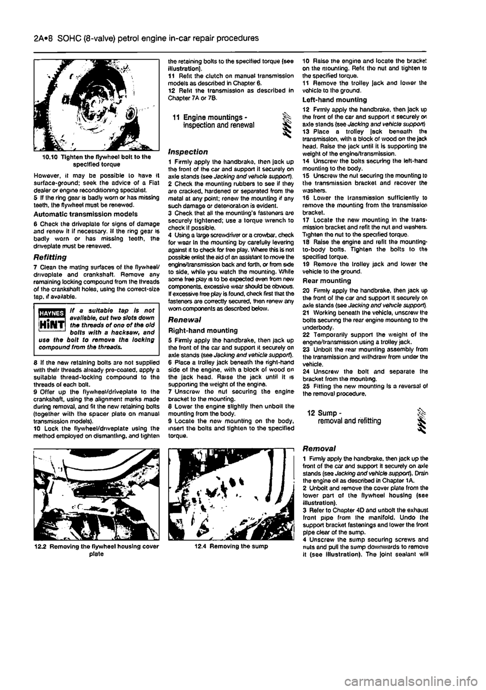
10.10 Tighten the flywheel bolt to the specified torque However, it may be possible lo have it surface*ground; seek (he advice of a Rat dealer or engine reconditioning specialist, 5 If Ihe ring gear is badly worn or has missing teeth, the flywheel must be renewed. Automatic transmission models 6 Check the driveplate for signs of damage and renew it if necessary. If the ring gear is badly worn or has missing teeth, the driveplate must be renewed.
Refitting 7 Clean the mating surfaces of the flywheel/ drivoplate and crankshoft. Remove any remaining locking compound from the threads of the crankshaft holes, using the correct-size tap. if available.
ft a suitable tap fs not . # | available, cut two slots down jHlNTI
toe
threads of ono of the old bolts with a hacksaw, and use the bolt to remove the locking compound from the throads.
8 If the new retaining bolts are not supplied with their threads already pre-coated, apply a suitable thread-locking compound to the threads of each bolt. 9 Offer up the fiywhee'/drlveplate lo the crankshaft, using the alignment marks made during removal, and fit the new retaining bolts (together with the spacer plate on manual transmission models), 10 Lock the flywheel/dnveplate using Ihe method employed on dismantling, and tighten
the retaining bolts to the specified torque (see illustration), 11 Refit the clutch on manual transmission models as described in Chapter 6. 12 Relit the transmission as described In Chapter 7A or 78.
11 Engine mountings • inspection and renewal
inspection 1 Firmly apply the handbrake, then jack up the front of the car and support it securely on axle stands (see Jacking and vehicle support). 2 Check Ihe mounting rubbers to see if they are cracked, hardened or separated from the metal at any point; renew the mounting if any such damage or deterioration is evident. 3 Check that all the mounting's fasteners are securely tightened; use a torque wrench to check II possible. 4 Using a large screwdriver or a crowbar, check for wear In the mounting by carefuliy levering against It to check for free play. Where this is not possible enlist the
aid
of
an
assistant to move the engina/transmission back
and
forth, or from s»de to side, while you watch the mounting. While some free play rs to bo expected even from new components, excessive wear
should
be obvious. If excessive free play is found, check first that the fasteners are correctly secured, then renew any worn components as described below.
Renewal Right-hand mounting 5 Firmly apply the handbrake, then jack up the front of the car and support it securely on axle stands (see Jacking and vehicle support). 8 Place a trolley jack beneath the right-hand side of Ihe engine, with a block of wood on the jack head. Raise the jack until it is supporting the weight of the engine. 7 Unscrew the nut securing the engine bracket to the mounting. 8 Lower the engine slightly then unboll the mounting from the body. 9 Locate the new mounting on the body, insert the bolts and tighten to the specified torque.
10 Raise tne engine and locate the bracket on the mounting. Refit tho nut and tighten lo the specified torque. 11 Remove the trolley jack and lower the vehicle to the ground. Left-hand mounting 12 Firmly apply the handbrake, then jack up the front of the car and support it securely on axle stands (see Jacking and vehicle support) 13 Place a trolley |sck beneath the transmission, with a block of wood on the jack head. Raise the jack until it is supporting tne weight of the engine/transmission. 14 Unscrew Ihe bolts securing the left-hand mounting to tho body. 15 Unscrew the nut securing ihe mounting to the transmission bracket and recover the washers. 16 Lower the transmission sufficiently to remove the mounting from the transmission bracket. 17 Locate the new mounting In the trans-mission bracket and refit the nut and washers. Tighten the nut to the specified torque. 18 Raise the engine and refit the mounting-to-body bolts. Tighten the bolts to the specified torque. 19 Remove the Irolloy jack and lower the vehicle lo the ground. Rear mounting 20 Firmly apply the handbrake, then Jack up the front of the car and support It securely on axle stands (see Jacking and vehicle support). 21 Working beneath Ihe vehicle, unscrew Ihe bolts secunng the rear engine mounting to the underbody. 22 Temporarily support the weight of the engine/transmission using a trolley jack. 23 Unbolt the rear mounting assembly from Ihe transmission and withdraw from under the vehicle. 24 Unscrew the bolt and separate Ihe bracket from tlve mounting. 28 Fitting the new mounting Is a reversal of the removal procedure.
12 Sump -removal and refitting
12.2 Removing the flywheel housing cover plate 12.4 Removing the sump
Removal 1 Firmly apply the handbrake, then jack up the front of the car and support it securely on axle stands (see Jacking and vehicle support). Drain the engine oil as described in Chapter 1 A. 2 Unbolt and remove the cover plate from the lower pari of the llywheel housing (see illustration). 3 Refer to Chapter 4D and unbolt the exhaust Iront pipe from Ihe manifold. Undo Ihe support bracket fastenings and lower the front pipe clear of the sump. 4 Unscrew the sump securing screws and nuts and pull the sump downwards to remove it (see Illustration). The joint sealant will
Page 59 of 225
2A*10 SOHC (8-valve) petrol engine in-car repair procedures
require cutting with a sharp Knife to release
the sump.
Clean away all old gasket material. Refitting
5
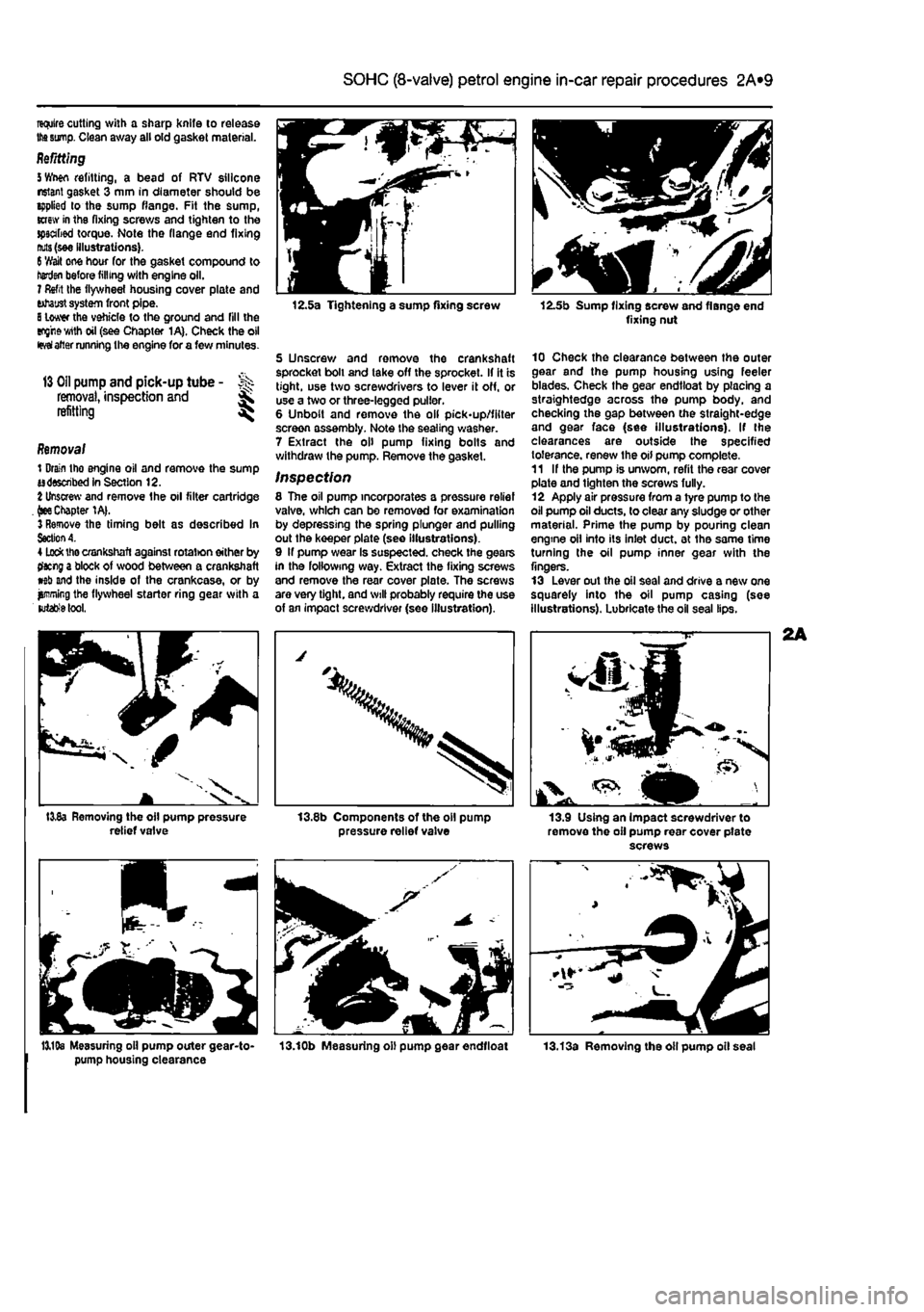
Wwn refitting, a bead of RTV silicone nsiant gasket 3 mm in diameter should be applied lo the sump flange. Fit the sump, screw in tha fixing screws and tighten to the spscabed torque. Note the flange end fixing
nuts
(see illustrations).
6
'//ait one hour for the gasket compound to henjai before filling with engine oil. 7 Refit the flywheel housing cover plate and tohaust system front pipe.
8
lower the vehicle to the ground and fill the eng'rewith oil (see Chapter 1A). Check the oil
fevai
alter running the engine for a few minutes.
13 Oil
pump and pick-up tube - >>>
removal,
inspection and ^ refitting ^
Removal 1 Drain tho engine oil and remove the sump adsswibed in Section 12.
%
Unscrew and remove the oil filter cartridge .
(see
Chapter 1A|. 3 Remove the timing belt as described In
Section A.
4
Lock
the crankshaft against rotat>on either by tfacng a block of wood between a crankshaft wb and the inside of the crankcase, or by jjmning the flywheel starter ring gear with a
lutabfe
tool.
I3v8a Removing the oil pump pressure relief valve
12.5a Tightening a sump fixing screw
5 Unscrew and remove the crankshaft sprocket boll and take off the sprocket. If it is tight, use two screwdrivers to lever it off, or use a two or three-legged puller. 6 Unbolt and remove the oil pick-up/filter screen assembly. Note the sealing washer. 7 Extract the oil pump fixing bolts and withdraw the pump. Remove the gasket.
Inspection 8 The oil pump incorporates a pressure relief valve, which can be removed for examination by depressing the spring plunger and pulling out the keeper plate (see illustrations). 9 If pump wear Is suspected, check the gears in the following way. Extract the fixing screws and remove the rear cover plate. The screws are very tight, and will probably require the use of an impact screwdriver (see illustration).
pressure relief valve
12.5b Sump fixing screw and flange end fixing nut
10 Check the clearance between the outer gear and the pump housing using feeler blades. Check the gear endtloat by placing a straightedge across the pump body, and checking the gap between the straight-edge and gear face (see illustrations). If the clearances are outside the specified tolerance, renew the oil pump complete. 11 If the pump is unworn, refit the rear cover plate and tighten the screws fully. 12 Apply air pressure from a tyre pump to the oil pump oil ducts, to clear any sludge or other material. Prime the pump by pouhng clean engine oil into its inlet duct, at the same time turning the oil pump inner gear with the fingers. 13 Lever out the oil seal and drive a new one squarely into the oil pump casing (see illustrations). Lubricate the oil seal lips.
13.9 Using an impact screwdriver to remove the oil pump rear cover pfate screws
13,19s Measuring oil pump outer gear-to- 13.10b Measuring oil pump gear endtloat pump housing clearance
Page 65 of 225
2B*5 DOHC (16-valve) petrol engine in-car repair procedures
4.11a Release the crankshaft TDC sensor wiring from the clip on the upper timing cover... throttle potentiometer and the Idle control stepper motor. Disconnect the coolant temperature sensor wiring connector located
in
the inlet manifold below the throttle body,
end
disconnect the brake servo vacuum hose. 15 Disconnect the wiring connectors for the fuel injector harness and the intake air temperature/pressure sensor, then fcconnect the fuel pressure regulator vacuum hose and the EVAP purge valve hose. 18 Undo the two bolts securing the plastic mlet manifold upper section to the lower section. Release the spark plug HT lead from the location groove in the manifold upper wctton, then lift the upper section, complete
»ith
throttle body, off the engine. Recover the 0-rngs from the manifold ports. 17 Unscrew the two bolts securing the fuel
4£1a Screw the spark plug bodies of the homo-made piston positioning tools into each spark plug hole ...
4.21b ... place a suitable washer or similar into the recess to keep the dowel rod vertical...
4.11b ... then slide the wiring plug and socket from the timing cover slot
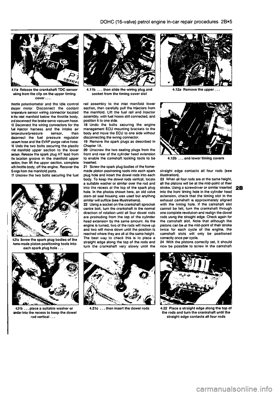
rail assembly to the inlet manifold lower section, then carefully pull the Injectors from the manifold. Lift the fuel rail and Injector assembly, with fuel hoses still connected, and position it to one side. 16 Undo the bolts securing the engine management ECU mounting brackets to the body and move the ECU to one side without disconnecting the wiring connector. 19 Remove the spark plugs as described in Chapter 1A. 20 Unscrew the two sealing plugs from the front and rear of the cylinder head extension to enable the camshaft locking tools to be inserted. 21 Screw the spark plug bodies of the home-made piston positioning tools into each spark plug hole and insert the dowel rods into each body. To keep the dowel rods vertical, locate a suitable washer or similar over Ihe rod and into the recess at the top of the spark plug hole. In the photos shown here, an old valve stem oil seal housing was used but anything similar will suffice (see illustrations). 22 Using a socket on the crankshaft sprocket centre bolt, turn the crankshaft in the normal direction of rotation until all four dowel rods are protruding from the top of the cylinder head extension by the same amount. As the engine is turned, two of the rods will move up and two will move down until the position is reached where they are all at the same hoight. The best way to check this is to place a straight edge along the top of the rods and turn the crankshafl very slowly until the
4.21c ... then insert the dowel rods
4.12b ... and lower timing covers
straight edge contacts all four rods (see illustration). 23 When all four rods are at the same height, all the pistons will be at the mid-point of their stroke. Using a screwdriver or similar inserted into the front timing hole in the cylinder head extension, check that the timing slot in the exhaust camshaft is approximately aligned with the liming hole. If the camshaft slot cannot be felt, turn the crankshaft through one complete revolution and realign the dowel rods using the straight edge. Check again for the camshaft slot. Note that although the pistons can be at the mid-point of their stroke twice for each cycle of the engine, the camshaft slots will only be positioned correctly once per cycle. 24 With the pistons correctly set, it should now be possible to screw in the camshaft
4.22 Place a straight edge along the top of the rods and turn the crankshaft until the straight edge contacts ail four rods
Page 71 of 225
DOHC (16-valve) petrol engine in-car repair procedures 2B*11
camshaft cover plate... 25 Locate the cam follower retaining tools in position and refit the cylinder head extension
as
described In Section 8.
10
Cylinder head - &
removal and
refitting S
Removal Note; The cylinder head bolts are of special
sekned
design and a Fiat tool should be
obtained
to unscrew them. A Ton key will not
JSt however
in practise It was found that a dose-httlng Alien key could be used as an itemative. 1 Drain the cooling system as described in Chapter 1A. 2 Remove the cylinder head extension as oescAbed
m
Section 8. 3 Disconnect the radiator hose from the thermostat housing on the left-hand end of
Ihe
cylinder head. 4 Disconnect the heater hose from the outlet
at the
rear of the cylinder head. 5 Disconnect the coolant temperature sensor md temperature gauge sensor wiring plugs
torn
the left-hand end of the cylinder head. 9 Undo the engine oil dipstick tube bracket retaining bolt and the two bolts securing the wing harness support clips to the inlet marriold lower section. 7 Undo Ihe retaining nuts and separate the ixhaust system front pipe from the exhaust manifold flange.
8
Check that nothing remains attached to the cinder head likely to impede removal. It Is assumed that the head will be removed complete with exhaust manifold and inlet manifold lower section. 9 Unscrew the cylinder head bolts half a turn K
e
time in the reverse order to that shown in (lustration 10.20a. When the bolts are free. «mwe them from their locations.. Id Lift the cylinder head from the block. If it is stuck tight rock the head to break the joint by mans of the manifolds. On no account drive
levers
into the gasket Joint, nor attempt to tap tf« head sideways, as it is located on positioning dowels. 11 Remove and discard the cylinder head gasket.
JK'
l^. 9.22b ... then apply RTV gasket sealant to the cover plate contact face 12 Refer to Chapter 20 for cylinder head dismantling and inspection procedures. Preparation for refitting 13 The mating faces of the cylinder head and cylinder block must be perfectly dean before refitting the head. Use a hard plastic or wooden scraper to remove all traces of gasket and carbon; also clean the piston crowns, Take particular care when cleaning the piston crowns as the soft aluminium alloy is easily damaged. Make sure that the carbon is not allowed to enter the oil and water passages -this Is particularly important for the lubncahon system, as carbon could block the oil supply to the engine's components. Using adhesive tape and paper, seal the water, oil and bolt holes in the cylinder block. To prevent carbon entering the gap between the pistons and bores, smear a little grease In the gap. After cleaning each piston, use a small brush to remove all traces of grease and carbon from the gap. then wipe away the remainder with a clean rag. Clean all the pistons in the same way. 14 Check the mating surfaces of the cylinder block and the cylinder head for nicks, deep scratches and other damage. If slight, they may be removed carefully with a file, but If excessive, machining may be the only alternative to renewal. If warpage of the cylinder head gasket surface Is suspected, use a straight-edge to check it for distortion. Refer to Part 0 of this Chapter if necessary. 15 Check the condition of the cylinder head bolts, and particularly their threads, whenever they are removed. Wash the bolts In a suitable
sequence
9.24 Lubricate the cam followers and place them in position in their respective bores solvent, and wipe them dry. Check each bolt for any sign of visible wear or damage, renewing them if necessary.
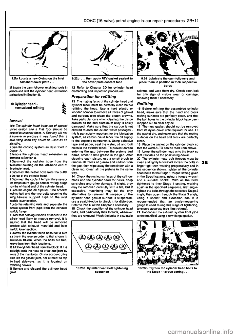
Refitting 18 Before refitting the assembled cylinder head, make sure that the head and block mating surfaces are perfectly clean, and that the bolt holes in the cylinder block have been mopped out to clear any oil, 17 The now gasket should not be removed from its nylon cover until required for use. Fit Ihe gasket dry, and make sure that the mating surfaces on the head and block are perfectly clean. 18 Place the gasket on the cylinder block so that the word ALTO can be read from above. 19 Lower the cylinder head onto the block so that it locates on the positioning dowel. 20 The cylinder head bolt threads must be clean and lightly lubricated. Screw the bolts in finger-tight then working progressively and in the sequence shown, lighten all the cylinder head bolts to the Stage 1 torquo setting given In the Specifications, using a torque wrench and a suitable socket. With all the bolts tightened to their Stage 1 setting, working again in the specified sequence, first angle-tighten the bolts through the specified Stage 2 angle, then again through the Stage 3 angle, using a socket and extension bar. It Is recommended that an angle-measuring gauge Is used during this stage ot tightening, to ensure accuracy (see Illustrations). 21 Reconnect the exhaust system front pipe to the manifold using a new flange gasket.
10.20b Tighten the cylinder head bolts to the Stago 1 torque setting ...
Page 82 of 225
2C*2 Diesel engine in-car repair procedures
9.31c Removing the inner timing cover
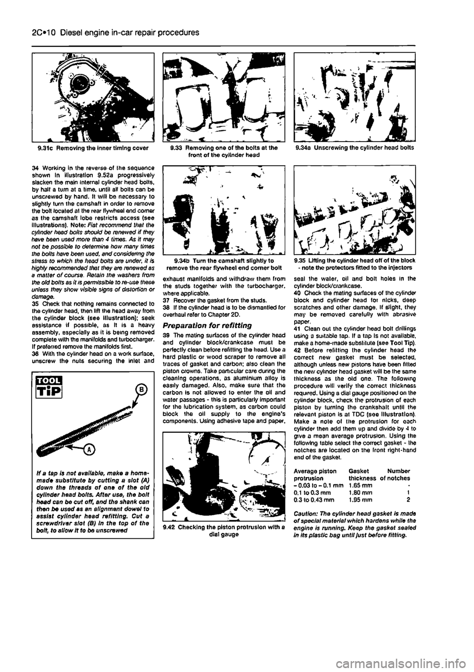
34 Working in ihe reverse of Ihe sequence shown In illustration 9.52a progressively slacken the main Internal cylinder head bolts, by halt a turn at a time, until all bolts can be unscrewed by hand. It will be necessary to slightly turn the camshaft in order to remove the bolt located at the rear llywheel end comer as the camshaft lobe restricts access (see illustrations). Note: Fiat recommend that the cylinder head boils should be renewed if they have been used more than 4 times. As It may not be possible to determine how many times the bolts have been used. end considering the stress to which the head bolts are under, it is highly recommended that they are renewed as a matter of course. Retain ihe washers from the old bolts as it is permissible to re-use these unless they show visible signs of distortion or damage. 35 Check that nothing remains connected to the cylinder head, then lift the head away from the cylinder block (see Illustration); seek assistance if possible, as It is a heavy assembly, especially as it is being removed complete with the manifolds and turbochargar. If preferred remove the manifolds first. 36 With the cylinder head on a work surface, unscrew the nuts securing the inlet and
3.33 Removing one of the bolts at the front of the cylinder head 9.34a Unscrewing the cylinder head bolts
ff a tapis not available, make a home-made substitute by cutting a slot (A) down the threads of one of the old cylinder head bolts. After use, the bolt head can be cut off, and the shank can then be used as an alignment dowel to assist cylinder head refitting. Cut a screwdriver slot (B) In the top of the bolt, to allow it to be unscrewed
9.34b Turn the camshaft slightly to remove the rear flywheel end comer boit exhaust manifolds and withdraw them from the studs together with the turbocharger. where applicable. 37 Recover the gasket from the studs. 38 If the cylinder head is to be dismantled for overhaul refer to Chapter 2D. Preparation for refitting 39 The mating surfaces of the cylinder head and cylinder block/crankcase must be perfectly clean before refitting the head. Use a hard plastic or wood scraper to remove all traces of gasket and carbon; also dean the piston crowns, Take particular care during the cleaning operations, as aluminium alloy is easily damaged. Also, make sure that the carbon is not allowed to enter the oil and water passages - this is particularly important for the lubrication system, as carbon could block the oil supply to the engine's components. Using adhesive tape and paper.
9.42 Checking the piston protrusion with a dial gauge
9.35 Lifting the cylinder head off of the block - note the protectors fitted to the injectors seal the water, oil and bolt holes In the cylinder block/crankcase. 40 Check the mating surfaces of the cylinder block and cylinder head for nicks, deep scratches and other damage. If slight, (hey may be removed carefully with abrasive paper, 41 Clean out the cylinder head bolt drillings using a suitable tap, If a tap Is not available, make a home-made substitute (see Tool Tip). 42 Before refitting the cylinder head th* correct new gasket must be selected, although unless new pistons have been fitted the new cylinder head gasket will be the same thickness as the old one. The following procedure will verify the correct thickness required. Using a dial gauge positioned on the cylinder block, check the protrusion of each piston by turning the crankshalt until the relevant piston Is at TDC (see Illustration). Make a note of the protrusion for oach cylinder then add them up and divide by 4 to give a mean average protrusion, Using the following table select the correct gasket - Ihe notcnes are located on the Iront right-hand end of (he gasket.
Average piston Gasket Number protrusion thickness of notches -0.03 to -0.1 mm 1.65 mm
0.1
to 0.3 mm 1.80 mm 1 0.3 to 0.43 mm 1.95 mm 2
Caution: The cylinder head gasket Is made of special material which hardens while the engine is running. Keep the gasket sealed in Its plastic bag until Just before fitting.
Page 85 of 225
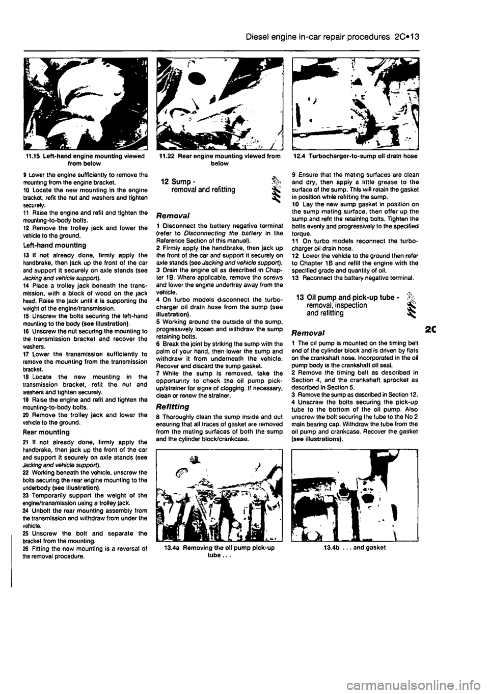
11.15 Left-hand engine mounting viewed from below 9 lower the engine sufficiently to remove the mounting from the engine bracket. 10 Locate the new mounting in the engine bracket, refit the nut and washers and tighten securely. 11 Raise the engine and refit and tighten the mounting-to-body bolts. 12 Remove the trolley jack and lower the vehicle to the ground. Left-hand mounting 13 If not already done, firmly apply the handbrake, then jack up the front of the car and support It securely on axle stands (see
Jacking
and vehicle support). 14 Place a trolley jack beneath the trans-mission. with a block of wood on the jack head. Raise the jack until it is supporting the weight of the engine/transmission. 15 Unscrew the bolts securing the left-hand mounting to the body (see Illustration). 16 Unscrew the nut securing the mounting to the transmission bracket and recover the washers. 17 Lower the transmission sufficiently to remove the mounting from the transmission bracket. 18 Locate the new mounting in the transmission bracket, refit the nut and washers and tighten securely. 19 Raise the engine and refil and tighten the mounting-to-body bolts. 20 Remove the trolley jack and lower the vehicle to the ground. Rear mounting 21 If not already done, firmly apply the handbrake, then jack up the front of the car and support it securely on axle stands (see
Jacking
and vehicle support). 22 Working beneath the vehicle, unscrew the bolts securing the rear engine mounting to the underbody (see illustration). 23 Temporarily support the weight of the engine/transmission using a trolley jack. 24 Unbolt the rear mounting assembly from the transmission and withdraw from under the vehicle. 25 Unscrew the bolt and separate the bracket from the mounting. 28 Fitting the new mounting is a reversal of tha removal procedure.
Diesel engine in-car repair procedures 2C*11
11.22 Rear engine mounting viewed from below
12 Sump -removal and refitting
Removal 1 Disconnect the battery negativo terminal (refer to Disconnecting the battery in the Reference Section of this manual). 2 Firmly apply the handbrake, then jack up the front of the car and support it securely on axie stands (see Jacking and vehicle support). 3 Drain the engine oil as described in Chap-ter 1B. Where applicable, remove the screws and lower the engine undertray away from the vehicle. 4 On turbo models disconnect the turbo-charger oil drain hose from the sump (see illustration). 5 Working around the outside of the sump, progressively loosen and withdraw the sump retaining bolts. 6 Break the joint by striking the sump with the palm of your hand, then lower the sump and withdraw it from underneath the vehicle. Recover and discard the sump gasket. 7 While the sump Is removed, take the opportunity to check the oil pump pick-up/strainer for signs of clogging. If necessary, clean or renew the strainer.
Refitting 8 Thoroughly clean the sump inside and out ensuring that all traces of gasket are removed from the mating surfaces of both the sump and the cylinder block/crankcase.
12.4 Turbocharger-to-sump oil drain hose
9 Ensure that the mating surfaces are clean and dry, then apply a little grease to the surface of the sump. This will retain the gasket in position while refitting the sump. 10 Lay the new sump gasket In position on the sump mating surface, then offer up the sump and refit the retaining bolts. Tighten the bolts evenly and progressively lo the specified torque. 11 On turbo models reconnect the turbo-charger oil drain hose. 12 Lower the vehicle to the ground then refer to Chapter 1B and refill the engine with the specified grade and quantity of oil. 13 Reconnect the battery negative terminal.
13 Oil pump and pick-up tube -removal, inspection and refitting
Removal 1 The oil pump Is mounted on the timing belt end of the cylinder block and is driven by flats on the crankshaft nose. Incorporated In the oil pump body is the crankshaft oil seal. 2 Remove the timing belt as described in Section 4, and the crankshaft sprocket as described in Section 5. 3 Remove the sump as described in Section 12. 4 Unscrew the bolts securing Ihe pick-up tube to the bottom of the oil pump. Also unscrew the bolt securing the tube to the No 2 main bearing cap. Withdraw the tube from the oil pump and crankcase. Recover the gasket (see illustrations).
13.4a Removing the oil pump pick-up tube... 13.4b ... and gasket