Rele FIAT PUNTO 1998 176 / 1.G Owners Manual
[x] Cancel search | Manufacturer: FIAT, Model Year: 1998, Model line: PUNTO, Model: FIAT PUNTO 1998 176 / 1.GPages: 225, PDF Size: 18.54 MB
Page 207 of 225
11
*6 Bodywork and fittings
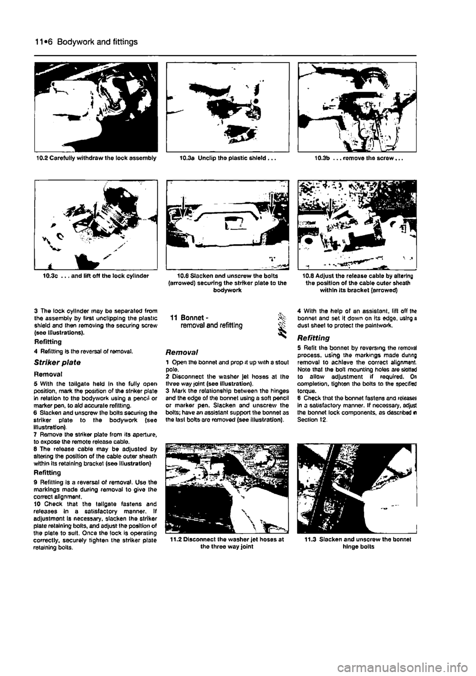
10.3c ... and lift off die lock cylinder
3 The lock cylinder may be separated from the assembly by first uncllpplng the plastic shield and then removing the securing screw (see Illustrations). Refitting 4 Refitting is Ihe reversal of removal.
Striker plate
Removal 5 With the tailgate held In the fully open position, mark the position of the striker plate In relation to the bodywork using a pencil or marker pen, to aid accurate refitting. 6 Slacken and unscrew the bolts securing the striker plate to the bodywork (see Illustration) 7 Remove the striker plate from its aperture, to expose the remote release cable. 8 The release cable may be adjusted by altering the position of Ihe cable outer sheath wKhin its retaining bracket (see illustration) Refitting 9 Refitting is a reversal of removal. Use the markings made during removal to givo Ihe correct alignment. 10 Check that the tailgate fastens and releases in a satisfactory manner. If adjustment Is necessary, slacken the striker plate retaining bolts, and adjust Ihe position ot the plate to suit. Once the lock is operating correctly, securely tighten the striker plate retaining bolls.
10.3a Unclip tho plastic shield... 10.3b ... remove the screw...
10.8 Slackon and unsorew the bolts (arrowed) securing the strfker plate to the bodywork
Si
10,8 Adjust the rolease cable by altering the position of the cable outer sheath within its bracket (arrowed)
11 Bonnet-removal and refitting
Removal 1 Open the bonnet and prop it up with a stout pole. 2 Disconnect the washer Jet hoses at the three way joint (see illustration), 3 Mark the relationship between the hinges and the edge of the bonnet using a soft pencil or markor pen. Slacken and unscrew the bolts: have an assistant support the bonnet as the last bolts aro removed (see Illustration),
4 With the help of an assistant, lift off the bonnet and set it down on its edge, using a dust sheet to protect the paintwork.
Refitting 5 Refit the bonnet by reversing the removal process, using the markings made dunng removal to achieve the correct alignment. Note that the boll mounting holes are slotted to allow adjustment if required. On completion, tighten the bolts to the specified torque. 8 Check that the bonnet fastens and releases in a satisfactory manner. If necessary, adjust the bonnet lock components, as described
m
Section 12.
Page 208 of 225
Bodywork and fittings
11
*7
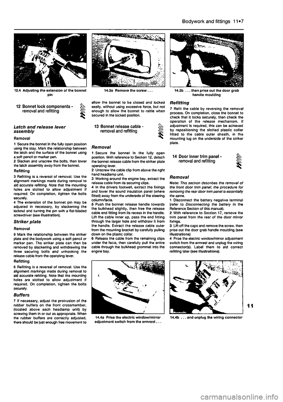
12.4 Adjusting the extension of the bonnet pin
12 Bonnet lock components - ^ removal and refitting H
Latch and release lever assembly
Removal 1 Secure the bonnet In the fully open position using the stay. Mark the relationship between the latch and the surface of the bonnet using a soft pencil or marker pen. 2 Slacken and unscrew the bolts, then lower the latch assembly away from the bonnot. Refitting 3 Refitting is a reversal of removal. Use the alignment markings made during removal to aid accurate refitting. Note that the mounting holes are slotted to allow adjustment if required. On completion, tighten the bolts securely. 4 The extension of the bonnet pin may be adjusted in necessary, by slackening the locknut and turning the pin with a flat-bladed screwdriver (see illustration).
Striker plate
Removal 5 Mark the relationship between the striker plate and the bodywork using a soft pencil or marker pen. The striker plate can then be removed by slackening and withdrawing the three securing bolts and unhooking the release cable from the operating lever. Refitting 6 Refitting is a reversal of removal. Use the alignment markings made during removal to aid accurate refitting. Note that the mounting holes are slotted to allow adjustment if required. On completion, tighten the bolts securely.
Suffers 7 If necessary, adjust the protrusion of the rubber buffers on the front crossmember, (located above each headlamp unit) by screwing them in or out as appropriate. When the rubber buffers are correctly adjusted, there should be just enough free movement to
14.3a Remove the screw .
allow the bonnet to be closed and locked easily, without using excessive force, but not enough to allow the bonnet to rattle when secured in the locked position.
13 Bonnet release cable -removal and refitting I
Removal 1 Secure the bonnet in the fully open position. With reference to Section 12, detach Ihe bonnet release cable from the striker plate operating lever. 2 Unscrew the cable clip from above the nght hand headlamp unit. 3 Working around the engine bay, extract the release cable from its securing clips. 4 In the drivers footweil, extracl Ihe fixings and lower the sound insulation panel (where fitted) away from the underside of the steering column/facia. 5 Push the bonnet release handle towards the bulkhead slightly, then free the release cable end fitting from its recess in the handle. Lift the cable inner up, pass the end fitting through the larger hole and withdraw it from the handle. Extract the release cable outer from the mounting bracket by carefully pulling down on the plastic collar. 6 Release the cable from the remaining clips under the facia, then carefully pull the entire cable through the bulkhead grommet Info the engine bay.
14.3b ... then prise out the door grab handle moulding
Refitting 7 Refit the cable by reversing the removal process. On completion, close the bonnet to check that it locks securely, then check the operation of tho release mechanism. If adjustment is required, this can be achieved by repositioning the slotted plastic collar fitted to the cable outer sheath, in the mounting lug on the underside of the striker plate.
14 Door inner trim panel -removal and refitting I
Removal Note: This section describes the removal of the front door trim panel; the procedure for removing the rear door trim panel is essentially the same, 1 Disconnect the battery negative terminal (refer to Disconnecting the battery in the Reference Section of this manual). 2 With reference to Section 17. remove the trim panel from the rear of the door mirror fixings. 3 Lift off the caps and remove the screw, then prise out the door grab handle moulding (see Illustrations) 4 Prise the electric window/mirror adjustment switch from the armrest and unplug the wiring connector(s). Label them to aid correct refitting later (see illustrations).
14.4a Prise the electric window/mirror adjustment switch from the armrest... 14.4b ... and unplug the wiring connector
Page 209 of 225
11
*8 Bodywork and fittings
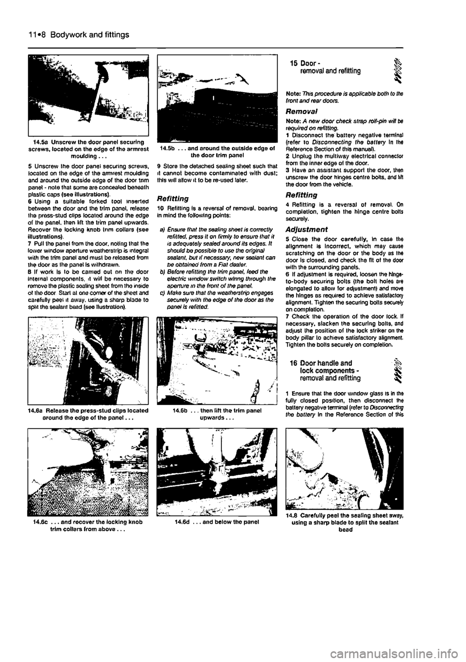
14.5a Unscrew the door panel securing screws, located on the edge of the armrest moulding... 5 Unscrew Ihe door panel securing screws, located on Ihe edge of the armrest moulding and around the outside edge of the door trim panel - note that some are concealed beneath plastic caps (see illustrations). 6 Using a Suitable forked tool inserted between the door end the trim panel, release Ihe press-stud clips located around Ihe edge of Ihe panel. Ihen lift the trim panel upwards. Recover the locking knob Inm collars (see illustrations). 7 Pull the panel from the door, noting that Ihe lower window aperture weatherstrip is integral with the trim panel and must bo released from the door as the panel Is withdrawn. B If work Is lo be earned out nn the door Internal oomponenls. it will be necessary to remove the plastic soaling sheet from tho inside ot the door Starl ol one comer of the sheet and carefully peel il away, using a sharp blade to split the sealant bead (see (lustration).
j
14.8a Release the press-stud clips located around the edge of tho panel...
trim collars from above...
14.5b ... and around the outside edge of the door trim panel
9 Store Ihe detached sealing sheet such that it cannot become contaminated with dust: this will allow it to be re-used later.
Refitting 10 Refilling Is a reversal of removal, bearing in mind the following points:
a) Ensure that the sealing sheet is correctly refitted, press it on firmly to ensure that it is adequately sealed around its edges. It should be possible fo use the origins} sealant, but if necessary, new sealant can be obtained from a Fiat dealer. b) Before refitting the trim panel, feed the electric window switch wlnng through the aperture in the front of Ihe panel. c) Make sure that the weatherstrip engages securely with the edge of the door as the panel Is refitted.
i4,6b ... then lift the trim panel upwards...
14.6d ... and below tho panel
15 Door- & removal and refitting is
Note: 7?ws procedure is applicable both to
the
front and rear doors.
Removal Note: A new door check strap rolbpin
win
be requited on refitting. 1 Disconnect the battery negative terminal (refer to O/sconoecf/ng fhe battery In Ihe Reference Section of this manual). 2 Unplug Ihe multiway electrical connector from the inner edge of the door. 3 Have an assistant support the door, then unscrew the door hinges centre bolts, and hit the door from the vehicle.
Refitting 4 Refitting is a reversal of removal. On completion, tighten the hinge centre bolts securely.
Adjustment 5 Close the door carefully, In case the alignment is incorrect, which may cause scratching on the door or the body BS the door is closed, and check the fit ot the door with the surrounding panels. 6 II adjustment Is required, loosen the hinge-to-body securing bolts (the bolt holes are elongated to allow lor adjustment) and move the hinges as required to achieve satisfactory alignment. Tighten the securing bolls securely on completion. 7 Check the operation of the door lock. If necessary, slacken the securing bolts, and adjust Ihe position of Ihe lock striker on the body pillar to achieve satisfactory alignment-Tighten the bolts securely on completion,
16 Door handle and lock components -removal and refitting ^
1 Ensure that the door window glass is in the fully closed position, then disconnect ihe battery negative terminal (refer to Drscoryiecfrrg fhe battery In the Reference Section of this
•
m-i -14.8 Carefully peel the sealing sheet away, using a sharp blade to spilt the sealant bead
Page 210 of 225
Bodywork and fittings
11
*9
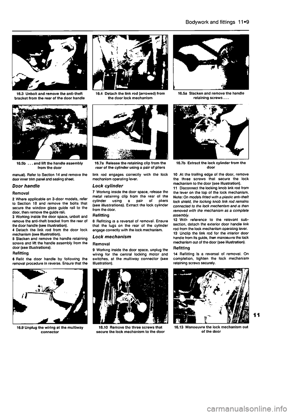
16.5b ... and lift the handle assembly from the door manual). Refer to Section 14 and remove the door inner trim panei and sealing sheet.
Door handle
Removal 2 Where applicable on 3-door models, refer to Section 18 and remove the bolts lhat secure the window glass guide rail to the door, then remove the guide rail. 3 Working inside the door space, unbolt and remove the anti-theft bracket from the rear of the door handle (see illustration). 4 Detach the link rod from the door lock mechanism (see Illustration). 5 Slacken and remove the handle retaining screws and lift the handle assembly from the door (see illustrations). Refitting 6 Refit the door handle by following the removal procedure in reverse. Ensure that the
connector
16.7a Release the retaining clip from the rear of the cylinder using a pair of pliors
link rod engages correctly with the lock mechanism operating lever.
Lock cylinder 7 Working inside the door space, release the metal retaining clip from the rear of the cylinder using a pair of pliers (see illustrations). Extract the lock cylinder from the door. Refitting 8 Refitting is a reversal of removal. Ensure thai the lugs on the rear of the cylinder engage correctly with the lock mechanism. Lock mechanism
Removal 9 Working inside the door space, unplug the wiring for the central locking motor and switches, at the multiway connector {see Illustration).
16.10 Remove the three screws that secure the lock mechanism to the door
16.7b Extract the lock cylinder Irom tho door
10 At the trailing edge of the door, remove Ihe three screws that secure the lock mechanism to the door (see Illustration). 11 Disconnect the locking knob link rod from the lever on the top of the lock mechanism. Note: On mode's fitted with a plastic anti-theft lock shield, the locking knob link rod remains connected to the lock mechanism and is then removed with the mechanism as a complete assembly. 12 With reference to the relevant sub-section. detach the exterior door handle link rod from the lock mechanism operating lever. 13 Unclip the link rod for the interior door handle from lis guide, I hen manoeuvre the lock mechanism out of the door (see illustration). Refitting
14 Refitting is a reversal of removal. On completion, tighten the lock mechanism retaining screws securely.
16.13 Manoeuvre the lock mechanism out of the door
Page 211 of 225
11
*10 Bodywork and fittings
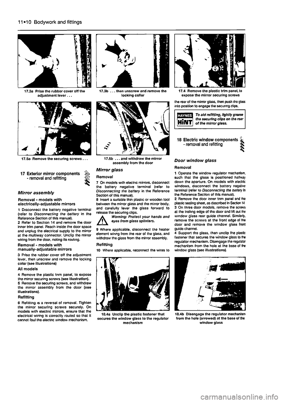
17.3a Prise the rubber cover off the adjustment lever... 17.3b ... then unscrew and remove the locking collar 17.4 Remove the plastic trim panel, to expose the mirror securing screws
Ihe rear of the mirror glass, then push tho glass into position fo engage the securing clips.
To aid re fitting, lightly
grease
^•-.—i the securing dips on the mar IjlllliTj of the mirror glass.
17.5a Remove the securing screws .
17 Exterior mirror components - removal and refitting
Mirror assembly
Removal • models with electrically-adjustable mirrors 1 Disconnect the battery negative terminal (refer to Disconnecting the battery in the Reference Section of this manual). 2 Refer to Section 14 and remove the door inner trim panel. Reach inside the door space and unplug the electrical supply to the mirror at the multiway connector. Unclip tho mirror wiring from Ihe door, noting its routing. Removal - models with manually-adjustable mirrors 3 Prise tho nibber cover off the adjustment lever, then unscrew and remove the locking collar (see Illustrations) Ail models 4 Remove the plastic tnm panel, to expose the mirror securing screws (see Illustration). 6 Remove the securing screws, and withdraw the mirror assembly from the door (see illustrations). Refitting 6 Refitting is a reversal of removal. Tighten the mirror securing screws securely. On models with electric mirrors, ensure that the electrical wiring is correctly routed so that it cannot foul the electric window mechanism.
17.6b ... and withdraw the mirror assembly from the door
Mirror glass
Removal 7 On models with electric mirrors, disconnect Ihe battery negative terminal (refer to Disconnecting the battery in the Reference Section of this manual). 8 Insert a suitable thin plastic or wooden tool between the mirror glass and the mirror body, and carefully lever the glass forward to release the securing clips. A Warning: Protect your hands and eyes from glass sp//nfers.
9 Where applicable, disconnect the heater element winng from the rear of the glass, and withdraw the glass from the mirror assembly. Refitting 10 Where applicable, reconnect the wires to
18 Electric window components & - removal and refitting 5
Door window glass
Removal 1 Operate the window regulator mechanism, such that the glass Is positioned halfway down the aperture. On modelo with electric windows, disconnect the battery negative terminal (refer to Disconnecting tho
battery
In the Reference Section of this manual). 2 Remove the door inner inm pane) ond ihe plastic sealing sheet, as described
In
Section
1
3 On three door models, remove the screws at Ihe trailing edge of the door and lift out the window glass rear guide channel. Similarly, remove the screws at the front edge at the door and remove the window glass front guide channel. 4 Support tho glass, (hen unclip the plastic fastener that secures the window glass to the regulator mechanism. Disengage the regulator mechanism from the hole at Ihe base of the window glass (see illustrations).
18.4a Unclip the plastic fastener that socures the window glass to the regulator mechanism
18.4b Disengage the regulator mechanism from the hole (arrowed) at the base of the window glass
Page 215 of 225
12*2 Body electrical systems
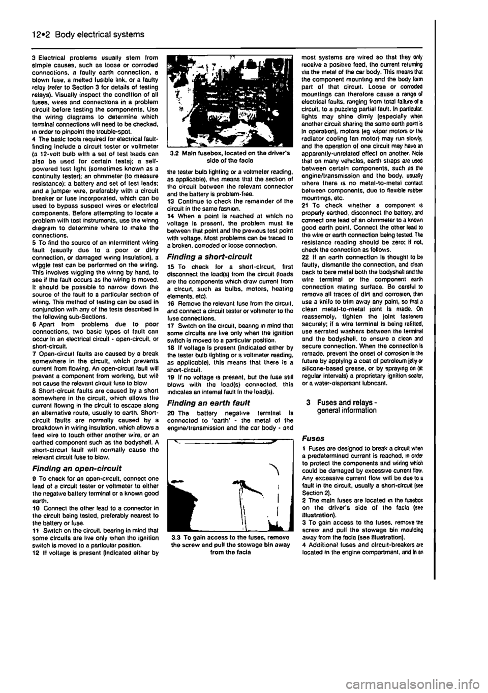
3 Electrical problems usually stem from simple causes, such as loose or corroded connections, a faulty earth connection, a blown fuse, a melted lusible link, or a fautty relay {refer to Section 3 for details of testing relays). Visually inspect the condition of all (uses, wires and connections in a problem circuit before testing the components. Use the wiring diagrams lo determine which terminal connections will need to be checked, in order to pinpoint the trouble-spot. 4 The basic tools required for electrical fault-finding include a circuit tester or voltmeter (a 12-volt bulb with a set of lest leads can also be used for certain tests}; a self-powered test light (sometimes known as a continuity tester); an ohmmeter (to measure resistance): a battery and set of tesi leads: and a lumper wire, preferably with u circuit breaker or fuse incorporated, which can be used to bypass susoect wires or electrical components. Before attempting to locate a problem with tost instruments, use the wiring diagram to determine where to make the connections. 5 To find the source of an intermittent wiring fault (usually due to a poor or dirty connection, or damaged wiring Insulation), a wiggle test can be performed on the wiring. This involves wiggling the wiring by hand, to see if tha fault occurs as the wiring Is moved. It should be possible to narrow down the source of the fault to a particular section of wiring. This method of testing can be used in conjunction with any of the tests descnbed in the following sub-Sections. 6 Apart from problems due to poor connections, two basic types of fault can occur in an electrical circuit - open-circuit, or short-circuit. 7 Open-circuit faults are caused by a break somewhere in the circuit, which prevents current from flowing. An open-circuit fault will prevent a component from working, but will not cause the relevant circuit fuse to blow 8 Short-circuit faults are caused by a shod somewhere in the circuit, which allows Die current flowing In the circuit to escape along an alternative route, usually to earth. Short-circuit faults are normally caused by a breakdown in wiring insulation, which allows a feed wire to touch either another wire, or an earthed component such as the bodysheli. A short-circuit fault will normally cause the relevant circuit fuse to blow.
Finding an open-circuit 9 To check for an opon-circuit, connect one lead of a circuit tester or voltmoter to either the negative battery terminal or a known good earth. 10 Connect the other lead to a connector in the circuit being tested, preferably nearest to the batter/ or luse. 11 Switch on the circuit, bearing In mind that some circuits are live only when tho ignition switch is moved to a particular position. 12 If voltage is present (Indicated either by
3.2 Main fuse box, located on the driver's side of the facie the toster bulb lighting or a voltmeter reading, as applicable), this means that tho section of Ihe circuit between the relevant connector and the battery is problem-free. 13 Continue to check the remainder ot the circuit in the same fashion. 14 When a point is reached at which no voltage Is present, the problem must lie between that point and the previous test point with voltage. Most problems can be traced to a broken, corroded or loose connection.
Finding a short-circuit 15 To check for a short-circuit, first disconnect the load(s) from the circuit (loads are the components which draw current from a circuit, such as bulbs, motors, heating elements, etc). 16 Remove the relevant luse Irom the circuit, and connect a circuit tester or voltmeter to the luse connections. 17 Switch on the circuit, beanng in mind that some circuits are live only when the ignition switch is moved to a particular position. 18 If voltage is present (indicated either by the tester bulb lighting or a voltmeter reading, as applicable), this means that there Is a short-circuit. 19 If no voltage is present, but the fuse still blows with the load(s) connected, this indicates an internal fault in the load(s).
Finding an earth fault 20 The battery negative terminal Is connected to 'earth' - the metal of the engine/transmission and the car body - and
I
IK
J 3.3 To gain access to the fuses, remove the screw and pull the stowage bin away from the facia
most systems are wired so that they only receive a positive feed, the current returning via the metal of Ihe car body. This means that the component mounting and the body form part of that circuit. Loose or corroded mountings can therefore cause a range of electrical faults, ranging from total failure ot a circuit, to a puzzling partial fault. In particular, lights may shine dimly (especially when another circuit sharing the same earth port In operation), motors (eg wiper motors v Ihe radiator cooling fan motor) may run slowly, and Ihe operation of one circuit may have an apparently-unrelated effect on another. Ncie that on many vehicles, earth straps axe uses between certain components, such as the engine/transmission and the body, usually whore there is no metal-to-metal contact between components, due to flexible rubber mountings, etc. 21 To check whether a component $ properly earthed, disconnect Ihe battery, and connect one lead of an ohmmeter to a kwwi good earth point. Connect the other lead to the wire or earth connection being tested. Tha resistance reading should be zero; if not. check the connection as follows. 22 If an earth connection Is thought to be faulty, dismantle the connection, and clean pack to bare metal both the bodysheli and ite wire terminal or the component earth connection mating surface. Be careful to remove all traces of dirt and corrosion, then use a knife to trim away any palm, so thai a clean metal-to-metal joint Is mads. On reassemoly, tighten the joint fasteners securely: if a wire terminal Is being refitted, use serrated washers between tho terminal and the bodysheli. to ensure a clean and secure connection. When the connection is remade, prevent the onset ot corrosion in the future by applying a coat of petroleum idly
or
stlicone-based grease, or by spraying on (a: regular intervals} a proprietary ignition eoater, or a water-aispersant lubneant.
3 Fuses and relays -general information
Fuses 1 Fuses are designod to break a circuit when a predetermined current is reached, in order to protect the components and wiring wttioh could be damaged by excessive current How. Any excessive current flow will be due to a fault in the circuit, usually a short-circuit (see Section 2). 2 The main fuses are located in the fusefcox on the driver's side of the facia (see illustration). 3 To gain access to the fuses, remove tne screw and pull the stowage bin moulding away from the facia (see illustration). 4 Additional fuses and circuit-breakers are located In the engine compartment, and in an
Page 216 of 225
Body electrical systems 12*3
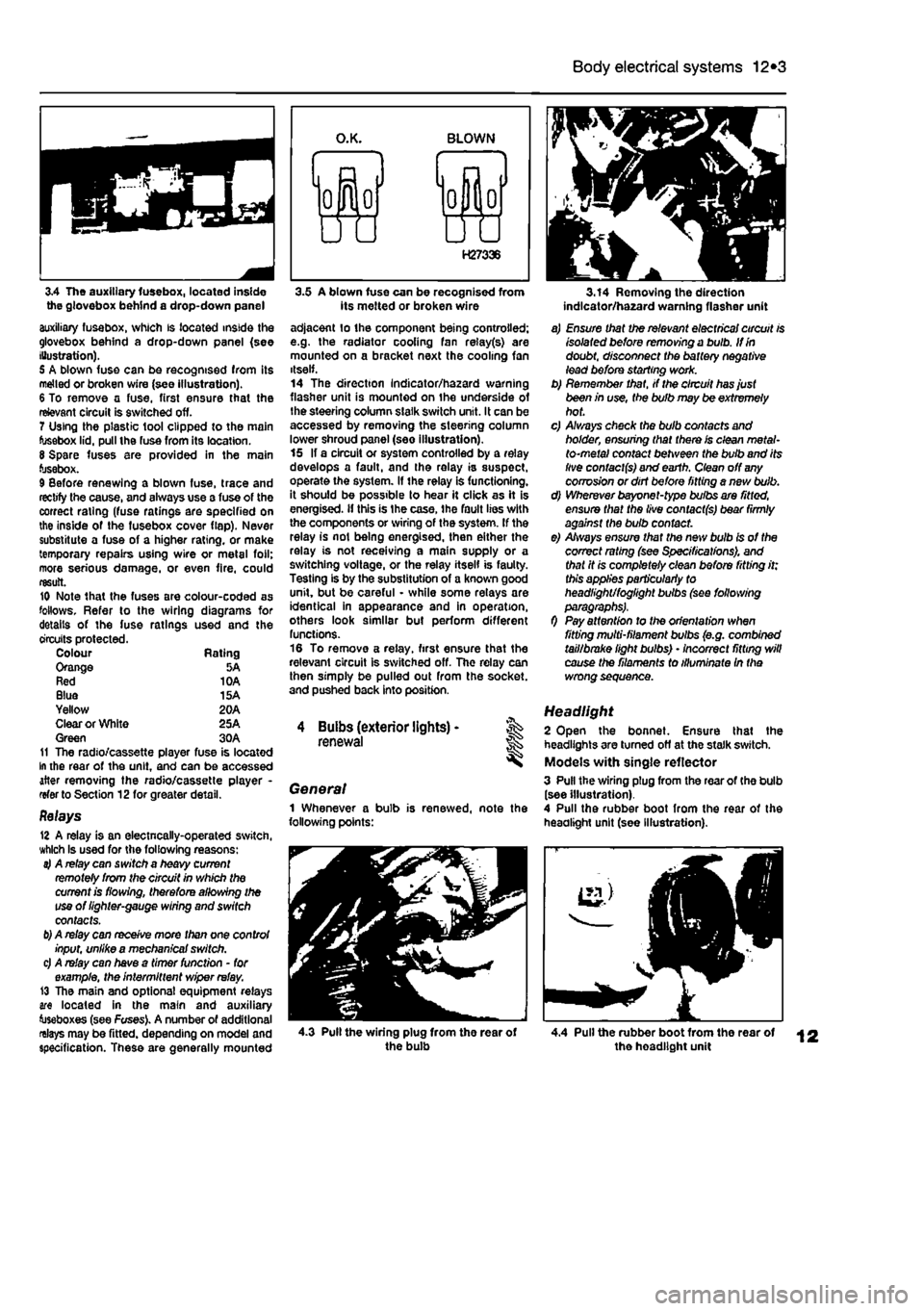
3.4 The auxiliary fusebox, located inside the glovebox behind a drop-down panel auxiliary fusebox, which is located inside the glovebox behind a drop-down panel (see Illustration). 5 A blown fuse can be recognised from its melted or broken wire (see illustration). 6 To remove a fuse, first ensure that the relevant circuit is switched off. 7 Using the plastic tool clipped to the main fusebox lid, pull the fuse from its location. 8 Spare fuses are provided in the main fusebox. 9 Before renewing a blown fuse, trace and rectify the cause, and always use a fuse of the correct rating (fuse ratings are specified on the inside of the fusebox cover flap). Never substitute a fuse of a higher rating, or make temporary repairs using wire or metal foil; more serious damage, or even fire, could result. 10 Note that the fuses are colour-coded as follows. Refer to the wiring diagrams for details of the fuse ratings used and the circuits protected. Colour Rating Orange 5A Red 10A Blue 15A Yellow 20A Clear or White 25A Green 30A 11 The radio/cassette player fuse is located In the rear of the unit, and can be accessed after removing the radio/cassette player -refer to Section 12for greater detail.
Relays 12 A relay is an electncally-operated switch, which Is used for the following reasons: 4 A relay can switch a heavy current remotely from the circuit in which the current is flowing, therefore allowing the use of lighter-gauge wiring and switch contacts.
b)
A relay can receive more than one control input, unlike a mechanical switch. c) A relay can have a timer function - for example, the intermittent wiper relay. 13 The main and optional equipment relays are located in the main and auxiliary toseboxes (see Fuses). A number of additional relays may be fitted, depending on model and specification. These are generally mounted
3.5 A blown fuse can be recognised from its melted or broken wire adjacent lo the component being controlled; e.g. the radiator cooling fan relay(s) are mounted on a bracket next the cooling fan itself. 14 The direction Indicator/hazard warning flasher unit is mounted on the underside of the steering column slalk switch unit. It can be accessed by removing the steering column lower shroud panel (see illustration). 15 If a circuit or system controlled by a relay develops a fault, and the relay is suspect, operate the system. If the relay is functioning, it should be possible to hear it click as it is energised, if this is Ihe case, the fault lies with the components or wiring of the system. If the relay is not being energised, then either the relay is not receiving a main supply or a switching voltage, or the relay itself is faulty. Testing is by the substitution of a known good unit, but be careful - while some relays are identical in appearance and in operation, others look similar but perform different functions. 16 To remove a relay, first ensure that the relevant circuit is switched off. The relay can then simply be pulled out from the socket, and pushed back into position.
4 Buibs (exterior lights) -renewal
General 1 Whenever a bulb is renewed, note the following points:
3.14 Removing the direction indlcator/ha2ard warning flasher unit
a) Ensure that the relevant electrical circuit is isolated before removing a bulb. If in doubt, disconnect the battery negative lead before starting work. b) Remember that, if the circuit has just been in use, the bulb may be extremely hot. c) A/ways check the bulb contacts and holder, ensuring that there is clean metal-to-metal contact between the bulb and its live contacts) and earth. Clean off
any
corrosion or dirt before fitting a nevt bulb. d) Wherever bayonet-type bulbs are fitted, ensure that the live contacts) bear firmly against the bulb contact. e) Always ensure that the new bulb is of the correct rating (see Specifications), and that it is completely clean before fitting it; this applies particularly to headlight/foglight bulbs (see following
0 Pay attention to the orientation when fitting multi-filament bulbs (e.g. combined tail/brake light bulbs) • incorrect fitting will cause the filaments to illuminate In the wrong sequence.
Headlight 2 Open the bonnet. Ensure that the headlights are turned off at the stalk switch. Models with single reflector 3 Pull the wiring plug from the rear of the bulb (see illustration). 4 Pull the rubber boot from the rear of the headlight unit (see Illustration).
4.3 Pull the wiring plug from the rear of the bulb 4.4 Pull the rubber boot from the rear of the headlight unit
Page 217 of 225
12*4 Body electrical systems
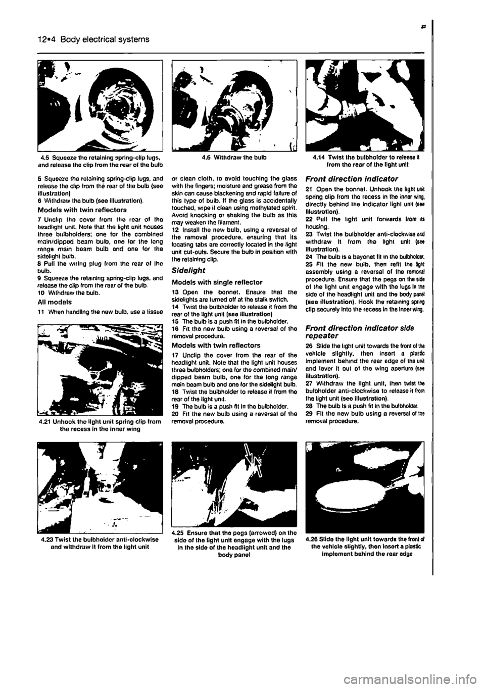
4.5 Squeeze the retaining spring-clip lugs, and release the clip from the rear erf the bulb
5 Squeeze the retaining spring-clip lugs, and release Ihe clip Irom the rear of the bulb {see illustration) 6 Withdraw the bulb (see illustration). Models with twin reflectors 7 Unclip Ihe cover from the rear of the headlight unit. Note that the light unit houses three bulbholders; one tor the combined main/dipped beam bulb, one for the long range main beam bulb and one for the sidelight bulb. 8 Pull Ihe wiring plug from the rear ol Ihe bulb. 9 Squeeze the retaining spring-clip lugs, and release tho clip from the rear of the bulb 10 Withdraw Ihe bulb. All models 11 When handling the new bulb, use a tissue
4.21 Unhook the light unit spring clip from the recess in the inner wing
4 6 Withdraw Ihe bulb
or clean cloth, to avoid touching Ihe glass wilh Ihe lingers; moisture and grease from the skin can cause blackening and rapid failure of this type of bulb. If the glass is accidentally touched, wipe it clean using methylated spirit. Avoid knocking or shaking the bulb as this may weaken the filament. 12 Install the new bulb, using a reversal of the removal procedure, ensuring that its locating tabs are correctly located in tho light unit cut-outs. Secure the bulb in position with Ihe retaining clip.
Sidelight
Models with single reflector 13 Open the bonnet. Ensure Ihat the sidelights are turned off at ihe stalk switch. 14 Twist the bulbholder lo release it from the rear of tho light unit (see illustration) 15 The bulb is a push fit in the bulbholder. 16 Fit the new bulb using a reversal of the removal procedure. Models with twin reflectors 17 Unclip the cover from Ihe rear of Ihe headlight unit. Note that Ihe light unit houses three bulbholders; one for the combined main/ dipped beam bulb, one for the long range main beam bulb and one (or the sidelight bulb. 18 Twist the bulbholder to release il from the rear of the light unit. 19 The bulb is a push fit in the bulbholder. 20 Fit Ihe new bulb using a reversal of the removal procedure.
4.14 Twist the bulbholder to release it from tho rear of tho light unit
Front direction indicator 21 Open the bonnet. Unhook tho light unit spring clip from the recess in the innsr wing, directly behind ihe indicator lighl unit (see illustration). 22 Pull the light unit forwards liom its housing. 23 Twist ihe bulbholder anti-clockwise and withdraw It from the light unit (see illustration). 24 The bulb is a bayonet fit in the bulbbdoer. 25 Fit the new bulb, then refil tho fight assembly using a reversal of Ihe remove! procedure. Ensure that the pegs on the side ol the lighl unit engage with the lugs in the side of the headlight unit and the body panel (see illustration). Hook the retaining spring clip securely Into the recess in the Inner
wing.
Front direction indicator
side
repeater 26 Slide the light unit towards the from
ol
the vehicle slightly, then insert a plastic Implement behind the rear edge of the unit and lever it oul ot the wing aperture (see illustration). 27 Withdraw the light unit. Ihen twist the bulbholder anti-clockwise to release
H
from the light unit (see illustration). 28 The bulb is a push fit in the bulbholder. 29 Fit the new bulb using a reversal of trie removal procedure.
4.26 Slide the light unit towards the front
of
the vehicle slightly, then Insert a plastic implement behind the rear edge
4.23 Twist the bulbholder anticlockwise and withdraw It from the light unit
4.25 Ensure that the pegs (arrowed) on tho sido of tho tight unit engage with the lugs In the side of the headlight unit and the body panel
Page 218 of 225
Body electrical systems 12*5
4.27 Withdraw the tight unH, then twist the bulbholder anti-clockwise to release it from the light unit
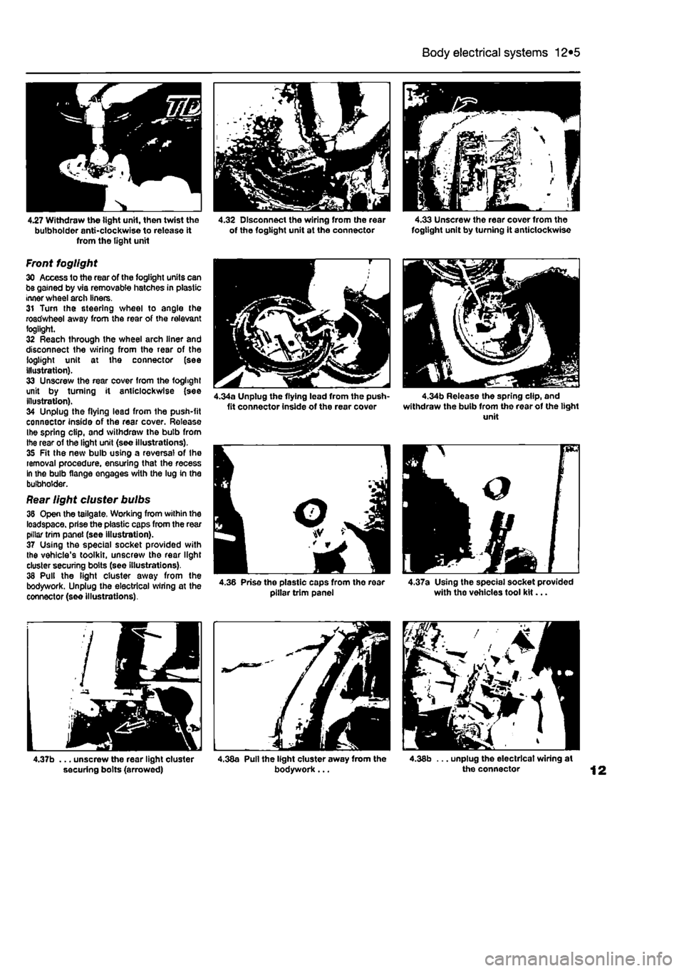
Front fogllght 30 Access to the rear of the fogllght units can be gained by via removable hatches in plastic inner wheel arch liners. 31 Turn the steering wheel to angle the roadwheel away from the rear of the relevant fogllght. 32 Reach through the wheel arch liner and disconnect the wiring from the rear of the fogllght unit at the connector (see illustration). 33 Unscrew the rear cover from the foghghl unit by turning it anticlockwise (see Illustration). 34 Unplug the flying lead from the push-fit connector inside of the rear cover. Release Ihe spring clip, and withdraw the bulb from the rear of the light unit (see illustrations). 35 Fit the new bulb using a reversal of Ihe removal procedure, ensuring that the recess In the bulb flange engages with the lug in the bulbholder.
Rear light cluster bulbs 38 Open the tailgate. Working from within the loadspace. prise the plastic caps from the rear pillar trim panel (see illustration). 37 Using the special socket provided with the vehicle's toolkit, unscrew the rear light cluster securing bolts (see illustrations). 38 Pull the light cluster away from the bodywork. Unplug the electrical wiring at the connector (see illustrations).
4.37b ... unscrew the rear light cluster securing bolts (arrowed)
4.32 Disconnect the wiring from the rear 4.33 Unscrew the rear cover from the of the fogtight unit at the connector fogllght unit by turning It anticlockwise
4.38a Pull the light cluster away from the 4.38b ... unplug the electrical wiring at bodywork... the connector
Page 219 of 225
12*6 Body electrical systems
4.39a Remove the screws...
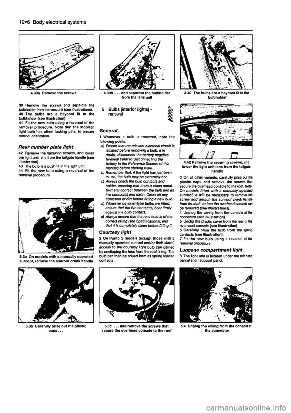
39 Remove the screws and separate the bulbholder from the lens unit (see Illustrations). 40 The bulbs are a bayonet (it in the bulbholder (s&e Illustration), 41 Fit the new bulb using a rovorsal of the removal procedure. Note that the stop/tall light bulb has offset locking pins, to ensure correct orientation.
Rear number plate light 42 Remove the securing screws, and lower the light unit lens from the tailgate handle (see Illustration), 43 The bulb Is a push fit In the light unit. 44 Fit the new bulb using a reversal of the removal procedure.
5.3a On models with a manually oporated sunroof, remove the sunroof crank handle
5.3b Carefully prise out the pfestic caps...
from the lens unit
5 Bulbs (interior lights) -renewal
General 1 Whenever a bulb is renewed, note Ihe following points: a) Ensure that the relevant electrical circuit is Isolated before removing a bulb. If
In
doubt, disconnect the battery negative terminal (refer to Disconnecting the battery In the Reference Section of this manual) before starting work. b) Remember that, if the light has just been in use, the bulb may be extremely hot. c) Always check the bulb contacts and holder, ensuring that there is clean metal-to-metal contact between the bulb and its live contacts) and earth, dean off any corrosion or dirt before fitting a new bulb. d) Wherever bayonet-type bulbs are fitted, ensure that the live contact(s) bear (irmly against the bulb contact. e) Always ensure that the new bulb is of the correct rating (see Specifications), and that it Is completely clean before fitting it.
Courtesy light 2 On Punto S models (except those with a manually operated sunroof end/or theft alarm) access to the courtesy light bulb can gained by unclipping the lens from the roof lining. The bulb can then be prised from its spring loaded contacts.
5.3c ... and remove the screws that secure the overhead console to the roof
buibhoidai
/ ' fl B 4.42 Remove the securing screws, and lower the light unit lens from the tailgate handle 3 On all other variants, carefully prise out the plastic caps and remove the screws that secure the overhead console lo the roof. Note: On models fitted with a manually operator sunroof, it will be necessary to remove
the
screw and detach the sunroof crank
handle
from its shaft, before the overhead console can be removed (see illustrations). A Unplug Ihe wiring from the console at the connector (see illustration). 5 Unciip the plastic cover from the rear ol the overhead console (see illustration). 6 Carefully prise the bulb from the spring contacts (see Illustration). 7 Fit the new bulb using a reversal of the removal procedure.
Luggage compartment light 8 The light unit is located under 1he left hand parcel shelf support panel.
5.4 Unplug Ihe wiring from (he console at the connector