relay FIAT PUNTO 1998 176 / 1.G User Guide
[x] Cancel search | Manufacturer: FIAT, Model Year: 1998, Model line: PUNTO, Model: FIAT PUNTO 1998 176 / 1.GPages: 225, PDF Size: 18.54 MB
Page 142 of 225
Fuel system - diesel models
4C*3
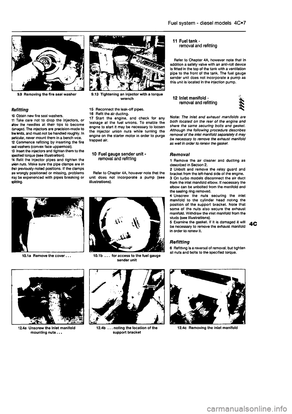
9.9 Removing the fire seal washor 9.13 Tightening an injector with a torque wrench
Refitting 10 Obtain new fire seal washers. 11 Take care not to drop the Injectors, or tfow the needles at their tips to become damaged. The injectors are prectsion-mado to Ine knits, and must not be handled roughly. In particular, never mount them in a bench vice. 12 Commence refitting by inserting the fire
seal
washers {convex face uppermost}. 13 Insert the injectors and tighten them to the specified torque (see illustration). 14 Refit the injector pipes and tighten the union nuts. Make sure the pipe clamps are in Iteir previously-noted positions. If the clamps
are
wrongly positioned or missing, problems may be expenenced with pipes breaking or splitting,
15 Reconnect the leak-off pipes. 16 Refit the air ducting. 17 Start the engine, and check for any leakage at the fuel unions. To enable the engine to start it may be necessary to loosen the Injector union nuts while turning the engine on the starter motor in order to purge trapped air.
10 Fuel gauge sender unit -removal and refitting
Refer to Chapter 4A, hov/ever note that the unit does not Incorporate a pump (see illustrations).
11 Fuel tank -removal and refitting
Refer to Chapter 4A, however note that in addition a safety valve with an anti-roll device is fitted in the top of the tank with a ventilation pipe to the front of the tank. The fuel gauge sender unit does not Incorporate a pump as this unit is located In the injection pump.
12 Inlet manifold - ^ removal and refitting %
Note: The Inlet and exhaust manifolds are both located on the rear of the engine and share the same securing bolts and gasket. Although the following procedure describes removal of the Inlet manifold separately it may be necessary to remove the exhaust manifold as well In order to renew the gasket.
Removal 1 Remove the air cleaner and ducting as described in Section 2. 2 Unbolt and remove the relay guard and bracket from the left-hand side of the engine. 3 On turbo models disconnect the air duct from the inlet manifold elbow. If necessary the elbow can be unbolted from the manifold and the sealing ring removed. 4 Unscrew the nuts securing the inlet manifold to the cylinder head noting the position of the support bracket. Note lhat some of the nuts also secure the exhaust manifold. Withdraw the inlet manifold from the studs (see illustrations), 5 Examine the gasket. If It is damaged it will be necessary to remove the exhaust manifold in order to renew it.
Refitting 6 Refitting Is a reversal of removal, but tighten all nuts and bolts lo the specified torque.
12.4c Removing the Inlet manifold
Page 143 of 225
Fuel system - diesel models 4C*3
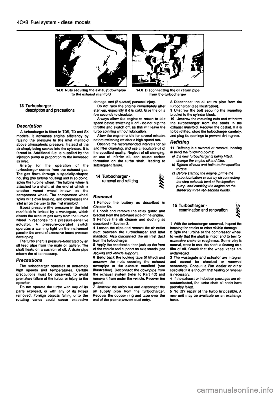
14.6 Nuts securing the exhaust downpipe to the exhaust manifold 14.8 Disconnecting the oil return pipe from tho turbocharger
13 Turbocharger -description and precautions
Description A turbocharger 1$ fitted to TDS, TD and SX models. It increases engine efficiency by raising the pressure In the inlet manifold above atmospheric pressure. Instead of the air simply being sucked Into the cylinders. It Is forced in. Additional fuel is supplied by the injection pump in proportion to the increased air inlet. Energy for the operation of the turbocharger comes from the exhaust gas. The gas flows through a specially-shaped housing (the turbine housing) and In so doing, spins the turbine wheel. The turbine wheel is attached lo a shaft, at the end of which is another vaned wheel known as the compressor wheel, The compressor wheel spins in Its own housing, snd compresses the inlet air on the way to the inlet manifold. Boost pressure (the pressure in the Inlet manifold) is limited by a wastegate, which diverts Ihe exhaust gas away from the turbine wheel In response to a pressure-sensitive actuator. A pressure-operaled switch operates a warning light on the instrument panel in the event of excessive boost pressure developing. The turbo shaft is pressure-lubricated by an oil feed pipe from the main oil gallery The shaft floats on a cushion of oil. A drain pipo returns the oil to the sump.
Precautions The turbocharger operates at extremely high speeds and temperatures. Certain precautions must be observed, to avoid premature failure of the turbo, or injury to the operator. Do not operate the turbo with any of its parts exposed, or with any of ils hoses removed. Foreign objects falling onto the rotating vanes could cause excessive
damage, and (if ejected) personal injury. Do not race the engine immediately after start-up, especially if it Is cold. Give the oil a few seconds lo circulate. Always allow the engine to return to idle speed before switching il off - do not blip the throttle and switch off, as this will leave the turbo spinning without lubrication. Allow the engine to idle lor several minutes before switching off after a high-speed run. Observe the recommended intervals for oil and filter changing, and use a reputable oil of the specified quality. Neglect of oil changing, or use of Inferior oil, can cause carbon formation on the turbo shaft, leading to subsequent failure.
14 Turbocharger -removal and refitting
8 Disconnect the oil return pipe from the turbocharger (see Illustration). 9 Unscrew the bolt securing the mounting bracket to the cyfindar block. 10 Unscrew the mounting nuts and withdraw the turbocharger from the studs in Ihe exhaust manifold. Recover the gasket. II It Is to be refitted, store the turbocharger carefully, and plug its openings to prevent dirt ingress.
Refitting 11 Refitting Is a reversal of removal, bearing in mind the fallowing points: a) if a new turbocharger Is being fitted, change the engine oil and filter. b) Tighten ail nuts and bolts to the specified torque. c) Before starting the engine, prime the turbo lubrication circuit by disconnecting the stop solenoid iead at the injection pump, and cranking the engine on the starter for three ten-second bursts.
Removal 1 Remove the battery as described in Chapter 5A. 2 Unbolt and remove the relay guard and bracket from the left-hand side of Ihe engine. 3 Remove the air cleaner and ducting as descnbed in Section 2. 4 Loosen the clips and remove the air outlet duct between tho turbocharger and inlet manifold. Also disconnect the air inlet duct from the turbocharger. 6 Appty the handbrake, then jack up tho front of the vohicle and support on axle stands (see Jacking and vehicle support). 6 Bend back the locking tabs (if fitted) and unscrew the nuts securing the exhaust downpipe lo the exhaust manifold (see Illustration). Disconnect the downpipe from the exhaust system (refer to Part 4D) end remove it from under the vehicle. Recover tne gasket. 7 Unscrew ihe union nut and disconnect the oil supply pipe from the turbocharger. Recover the copper ring and tape over the end of the pipe 10 prevent dust entry.
15 Turbocharger -examination and renovation l
1 With the turbocharger removed, inspect the housing for cracks or other visible damage. 2 Spin the turbine or the compressor wheel, to verify that the shaft is intact and to feel for excessive shake or roughness. Some play is normal, since in use, the shaft is floating on a film of oil. Check that the wheel vanes are undamaged. 3 The wastegate and actuator are Integral, and cannot be checked or renewed separately. Consul! a Flat dealer or other specialist If it is thought that testing or renewal is necessary. 4 If tho exhaust or induction passages are ail* contaminated, Ihe turbo shaft oil seals have probably failed. 6 No DIY repair of the turbo is possible. A new unit may be available on an exchange basis,
Page 144 of 225
4D«1
Chapter 4 Part D:
Exhaust and emission control systems
Contents
Catalytic converter - general Information and precautions 7 Crankcase emission system • general information 3 Evaporative loss emission control system • information and component renewal 2
Degrees of difficulty
Exhaust manifold - removal and refitting 5 Exhaust system - general information and component renewal .... 6 General information 1 Lambda oxygen sensor - removal and refitting 4
Easy, suitable
tor novice with fittie ^
1 experience
Fairly easy, suitable for beginner with ^ some experience ^
Fairiy dfficult, lb suitable for competent ^ DIY mechanic ^
Difficult, suitable for experienced DIY ^ mechanic
Very difficult, ^ suitable far expert DIY or professional
Specifications
Torque wrench settings Exhaust down pipe to manifold Exhaust manifold Exhaust system mounting Exhaust to catalytic converter: M8 M10x1.25
Nm Ibfft 24 18 24 18 27 20
24 18 40 30 53 39
1 General information
Emission control systems All petrol engine models use unleaded petrol and are controlled by engine management systems that are 'tuned' to give the best compromise between driveability. luel consumption and exhaust emission production. In addition, a number of systems are fitted that help to minimise other harmful emissions: a crankcase emission-control system (petrol models only) that reduces the release of pollutants from the crankcase, an evaporative loss emission control system (petrol models only) to reduce the release of hydrocarbons from the fuel tank, a catalytic converter (petrol and diesel models) to reduce exhaust gas pollutants, and an Exhaust Gas Recirculation (EGR) system (turbo diesel models only) to reduce exhaust emissions. Crankcase emission control To reduce the emission of unburned hydrocarbons from the crankcase Into the atmosphere, the engine is sealed and the blow-by gases and oil vapour are drawn from inside the crankcase, through a flame trap.
into the inlet tract to be burned by the engine during normal combustion. Under conditions of high manifold depression (idling, deceleration) the gases will by sucked positively out of the crankcase. Under conditions of low manifold depression (acceleration, full-throttle running) ihe gases are forced out of the crankcase by the (relatively) higher crankcase pressure: if the engine is worn, the raised crankcase pressure (due to increased blow-by) will cause some of the flow to return under all manifold conditions. Exhaust emission control -petrol models To minimise the amount of pollutants which escape Into the atmosphere, a catalytic converter is fitted In the exhaust system. The fuel system is of the closed-loop type, in which a Lambda (or oxygen) sensor In the exhaust system provides the engine management system ECU with constant feedback, enabling the ECU to adjust the air/fuel mixture to optimise combustion. The Lambda sensor has a heating element built-in that Is controlled by the ECU through the Lambda sensor relay to quickly bring the sensor's tip to Its optimum operating temperature. The sensor's tip Is sensitive to oxygen and relays a voltage signal to the ECU
that varies according on the amount of oxygen In the exhaust gas. If the inlet air/fuel mixture is too rich, the exhaust gases are low in oxygen so the sensor sends a low-voltage signal, the voltage rising as the mixture weakens and the amount of oxygen rises In the exhaust gases. Peak conversion efficiency of all major pollutants occurs if the inlet air/fuel mixture Is maintained at the chemlcally-con*ect ratio for the complete combustion of petrol of 14.7 parts (by weight) of air to
1
part of fuel (the stoichiometric ratio). The sensor output voltage alters in a large step at this point, the ECU using the signal change as a reference point and correcting the Inlet air/fuel mixture accordingly by altering the fuel Injector pulse width. Exhaust emission control -diesel models An oxidation catalyst is fitted in the exhaust system of all diesel engine models. This has the effect of removing a large proportion of the gaseous hydrocarbons, carbon monoxide and particulates present in the exhaust gas. An Exhaust Gas Recirculation (EGR) system Is fitted to all turbo diesel engine models. This reduces the level of nitrogen oxides produced during combustion by Introducing a proportion of the exhaust gas back into the inlet manifold, under certain engine operating
Page 150 of 225
5A«2 Starting and charging systems
Maintenance-free battery -charging Note: The following is intended as a guide only. Always refer to the manufacturer's recommendations (often printed on a label attached to the battery) before charging a battery. 13 This battery type takes considerably longer lo fully recharge than the standard type, the time taken being dependent on the extent of discharge, but it can take anything
up
to three days. 14 A constant voltage type charger is required, tooe set, when connected, to 13.9 to 14.9 votts wth a charger current below 25 amps. Using
mis
method, the battery should be usable within three hours, giving a voltage reading of 12.5 vofts. but this Is for a partially discharged battery and, as mentioned, full charging can
take
considerably longer. 15 If Ihe battery is to be charged from a fully discharged state {condition reading loss lhan 12.2 volts), have it recharged by your FIAT dealer or local automotive electrician, as Ihe charge rate is higher and constant super-vision during charging Is necessary.
3 Battery -removal and refitting
Note: Refer to Disconnecting the battery in ifte Reference Section of this manual before proceeding.
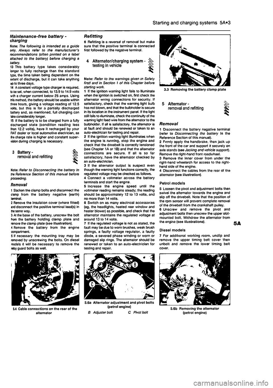
Removal 1 Slacken the clamp bolts and disconnect the ctamp from the battery negative (earth) terminal. 2 Remove the insulation cover (where fitted)
and
disconnect the positive terminal lead(s) in
Die same
way. 3 At the base of the battery, unscrew the bolt from the battery holding clamp plate and remove the clamp plate (see Illustration). A Remove the battery from Ihe engine compartment. 5 II necessary the mounting tray may be removed by unscrewing the bolts. On diesel models it will be necessary to remove the relay guard bolts as well.
Refitting 6 Refitting is a reversal of removal but make sure that the positive terminal is connected first followed by the negative terminal.
4 Alternator/charging system - >%•> testing in vehicle
Note: Refer to the warnings given in Safety first! and in Section 1 of this Chapter before starting work. 1 If the ignition warning light fails to Illuminate when the ignition is switched on, first check the alternator wiring connections for security. If satisfactory, check that the warning light bulb has not blown, and that the bulbholder is secure in its location in the instrument panel. If the light still fails to illuminate, check the continuity of the warning light feed wire from the alternator to the bulbholder. If all is satisfactory, the alternator is at fault and should be renewed or taken to an auto-electrician for testing and repair. 2 If the ignition warning light Illuminates when the engine Is running, stop the engine and check that the drivebelt is correctly tensioned (see Chapter 1A or 18) and that the alternator connections are secure. If all is so far satisfactory, have the alternator checked by an auto-electrician. 3 If the alternator output is suspect even though the warning light functions correctly, the regulated voltage may be checked as follows. 4 Connect a voltmeter across the battery terminals and start the engine. 5 Increase the engine speed until the voltmeter reading remains steady; the reading should be approximately 12 to 13 volts, and no more than 14 volts. 6 Switch on as many electrical accessories (eg. the headlights, heated rear window and heater blower) as possible, and check that the alternator maintains the regulated voltage at around 13 to 14 volts. 7 If ihe regulated voltage is not as stated, the fault may be due to worn brushes, weak brush springs, e faulty voltage regulator, a faulty diode, a severed phase winding or worn or damaged slip rings. The alternator should be renewed or taken to an auto-electrician for testing and repair.
3.3 Removing the battery clamp plate
5 Alternator -removal and refitting
Removal 1 Disconnect the battery negative terminal {refer to Disconnecting the battery In the Reference Section of this manual). 2 Firmly apply the handbrake, then jack up the front of the car and support it securely on axle stands (see Jacking and vehicle support). Remove tho right-hand front roadwheel. 3 Remove Ihe Inner cover from under the right-hand wheelarch for access to tho right-hand side of the engine. 4 Disconnect the cables from the rear Of the alternator (see illustration).
Petrol models 5 Loosen the pivot and adjustment bolts then swivel the alternator towards the engine and slip off the drivebelt. Note that the position of the rpm sensor will prevent complete removal of the drivebelt from the crankshaft puiley. 6 Unscrew and remove the pivot and adjustment bolts then unscrew the upper slot-mounted bolt. Withdraw the alternator from the engine (see illustrations).
Diesel models 7 For additional working room, unclip and remove the upper timing belt cover then unbolt and remove the lower timing belt cover.
5.4 Cable connections on the rear of the alternator
5.6a Alternator adjustment and pivot bolts (petrol engine) B Adjuster bolt C Pivot bolt 5.6b Removing the alternator (petrol engine)
Page 156 of 225
501
Chapter 5 PartC:
Preheating system - diesel models
Contents
Glow plugs - removal, inspection and refitting 2 Preheating system - description and testing 1 Preheating system control unit - removal and refitting 3
Degrees of difficulty
Ea3y, suitable
for &
novice with little
|| experience ^
Fairty easy,
suitable for beginner with
some experience
jQ
Fairty diffctit, ^
suitable
for competent
DIY
mechanic
Difficult, suitable for
experienced DIY JR mechanic ^
Very difficult, ^ suitable fbrexpertDfY JR or professional ^
Specifications
Torque wrench setting Nm ibf ft Heater glow plugs 15 11
1 Preheating system -description and testing
Description 1 Each swirl chamber has a heater plug (commonly called a glow plug) screwed into it. The plugs are electrically-operated before and during start-up when the engine is cold. 2 Electrical feed to the glow plugs Is controlled by a relay/timer unit. The coolant temperature determines the period of heating that takes place. 3 A warning light in the instnjment panel tells the driver that preheating is taking place. When the light goes out, the engine is ready to be started. The voltags supply to the glow plugs continues for several seconds after the light goes out, If no attempt is made to start, the timer then cuts off the supply, In order to avoid draining the battery and overheating the glow plugs.
Testing 4 If the system malfunctions, testing is ultimately by substitution of known good units, but some preliminary checks may be made as follows. 5 Connect a voltmeter or 12-volt test lamp between the glow plug supply cable and earth (engine or vehicle metal). Make sure that the live connection is kept clear of the engine and bodywork. 6 Have an assistant switch on the ignition, and check that vottage is applied to the glow plugs. Note the time for which the warning light Is lit. and the total time for which voltage Is applied before the system cuts out. Switch off the ignition. 7 At an under-bonnet temperature of 20°C. typical times noted should be 5 or 6 seconds for warning light operation, followed by a further 10 seconds supply after the light goes out. Warning light time will increase with lower temperatures and decrease with higher temp-eratures.
8 If there Is no supply at all, the relay or associated winng is at fault. 9 To locate a defective glow plug, disconnect the main supply cable and the interconnecting strap from the top of the glow plugs. Be careful not to drop the nuts and washers. 10 Use a continuity tester, or a 12-voH test lamp connected to the battery positive terminal, to check for continuity between each glow plug terminal and earth. The resistance of a glow plug in good condition is very low (less than 1 ohm), so if the test lamp does not light or the continuity tester shows a high resistance, the glow plug is certainly defective. 11 If an ammeter is available, the current draw of each glow plug can be checked. After an initial surge of 15 to 20 amps, each plug should draw approximately 12 amps. Any plug which draws much more or less than this is probably defective. 12 As a final check, the glow plugs can be removed and Inspected as described in the following Section.
Page 157 of 225
5C«2 Preheating system - diesel models
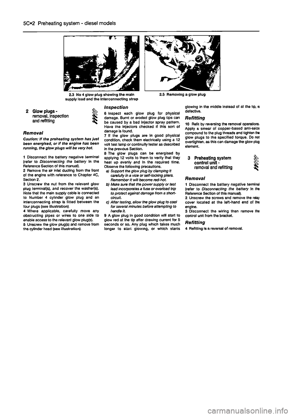
2.3 No 4 glow plug showing the main supply lead end the interconnecting strap 2.5 Removing a glow plug
2 Glow plugs -removal, Inspection and refitting
Removal Caution: If the preheating system has just been energised, or If tho engine has been running, the glow plugs will be very hot
1 Disconnect the battery negative terminal (refer to Disconnecting the battery in the Reference Section of this manual), 2 Remove Ihe air Inlet ducting from the front of the engine with reference to Chapter 4C, Section 2. 3 Unscrew the nut from the relevant glow plug lerminai(s). and recover the washer(s). Note that tho main supply cable is connected to Number 4 cylinder glow plug and an interconnecting strap lis fitted between the four plugs (see Illustration). 4 Where applicable, carefully move any obstructing pipes or wires lo one side to enable access to the relevant glow plug(s). 5 Unscrew the glow plug(s) and remove from the cylinder head (see illustration).
Inspection 8 Inspect each glow plug for physical damage. Burnt or eroded glow plug tips can bo caused by a bad Injector spray pattern. Have the Injectors checked if this sort of damage is found. 7 If Ihe glow plugs are In good physical condition, check them electrically using a 12 volt test lamp or continuity tester as described in the previous Section. 8 The glow plugs can be energised by applying 12 volts to them to verity that they heat up evenly and In the required time. Observe the following precautions. a) Support the glow plug by clamping it carefully in a vice or selNocking pliers. Remember it will become red-hot. b) Make sura that the power supply or test lead incorporates a fuse or overload trip to protect against damage from a short-circuit. c) After testing, allow the glow plug to cool for several minutes before attempting to handle it. 9 A glow plug In good condition will start to glow red at the tip after drawing current for 5 seconds or so. Any plug which takes much longer to start glowing, or which starts
glowing in the middle instead of at the lip, « defective. Refitting 10 Refit by reversing the removal operations. Apply a smear of copper-based anti-seize compound to the plug threads and tighten Ihe glow plugs to Ihe specified torque. Do not overtighten, as this can damage the glow plug element.
3 Preheating system control unit -removal
and
refitting I
Removal 1 Disconnect the battery negative terminal (refer to Disconnecting the baffery In Ihe Reference Section of this manual). 2 Unscrew the screws and remove the relay cover located at the left-hand end of the engine. 3 Disconnect the wiring then remove the control unit from the bracket. Refitting 4 Refitting is a reversal of removal.
Page 164 of 225
Manual transmission 7A*3
3,8 Unscrew the nut and disconnect the gear selector rod from the lever on the transmission unscrew the locknut and adjusting nut from the end of the clutch cable and disconnect the cable from the transmission. Recover the damper block. On models with a hydraulically operated clutch, unscrew the mounting bolts, release the slave cylinder pushrod from the re&ase arm on the transmission, then position the cylinder to one side.
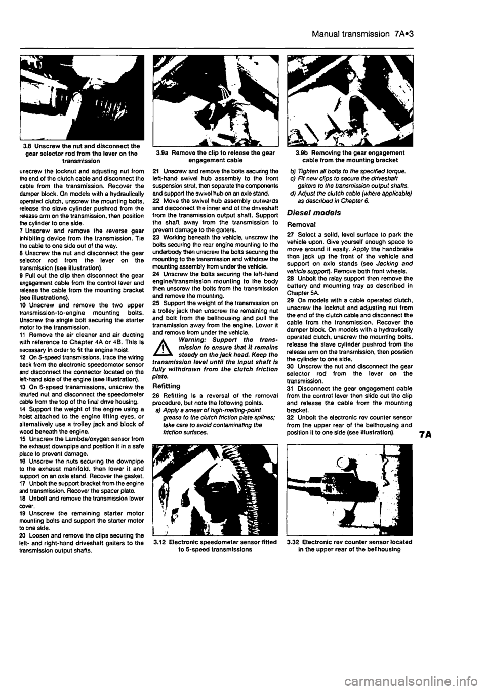
7 Unscrew and remove the reverse gear Inhibiting device from the transmission. Tie the cable to one side out of the way. 8 Unscrew the nut and disconnect the gear selector rod from the lever on the transmission (see illustration). 9 Pull out the clip then disconnect the gear engagement cable from the control lever and release the cable from the mounting bracket (see illustrations). 10 Unscrew and remove the two upper transmisslon-to-englne mounting bolts. Unscrew the single bolt securing the starter motor to the transmission. 11 Remove the air cleaner and air ducting with reference to Chapter 4A or 4B. This Is necessary In order to fit the engine hoist 12 On 5-speed transmissions, trace the wiring back from the electronic speedometer sensor and disconnect the connector located on the left-hand side of the engine (see illustration). 13 On 6-speed transmissions, unscrew the knurled nut and disconnect the speedometer cable from the top of the final drive housing. 14 Support the weight of the engine using a hoist attached to the engine lifting eyes, or alternatively use a trolley jack and block of wood beneath Ihe engine. 15 Unscrew the Lambda/oxygen sensor from the exhaust downpipe and position It In a safe place to prevent damage. 16 Unscrew the nuts securing the downpipe to the exhaust manifold, then lower It and support on an axle stand. Recover the gasket. 17 Unbolt the support bracket from the engine and transmission. Recover the spacer plate. 18 Unbolt and remove the transmission lower cover, 19 Unscrew the remaining starter motor mounting bolts and support tho starter motor to one side. 20 Loosen and remove the clips securing the left- and right-hand driveshaft gaiters to the transmission output shafts.
3.9a Remove the clip to release the gear engagement cable 21 Unscrew and remove the boils securing the left-hand swivel hub assembly to the front suspension strut, then separate the components and support the swivel hub on an axle stand. 22 Move the swivel hub assembly outwards and disconnect the inner end of the dnveshaft from the transmission output shaft. Support the shaft away from the transmission to prevent damage to the garters. 23 Working beneath the vehicle, unscrew the botts securing the rear engine mounting to the underbody then unscrew the bolts securing the mounting to the transmission and withdraw the mounting assembly from under the vehicle. 24 Unscrew the bolts securing the left-hand engine/transmission mounting to Ihe body then unscrew the bolts from the transmission and remove the mounting. 25 Support the woight of the transmission on a trolley jack then unscrew the remaining nut and bolt from the belihousing and pull the transmission away from the engine. Lower it and remove from under the vehicle. A Warning: Support the trans-mission to ensure that it remains steady on the jack head. Keep the transmission levet until the Input shaft Is fully withdrawn from the clutch friction plate. Refitting
26 Refitting is a reversal of the removal procedure, but note the following points. a) Apply a smear of high-melting-point grease to the clutch friction plate splines; take care to avoid contaminating the friction surfaces.
3.12 Electronic speedometer sensor fitted to 5-speed transmissions
3.9b Removing the gear engagement cable from the mounting bracket b) Tighten all bolts to Ihe specified torque. c) Fit new clips to secure the driveshaft gaiters to the transmission output shafts. d) Adjust the clutch cable (where applicable) as described In Chapter 6.
Diesel models
Removal 27 Seloct a solid, level surface to park the vehicle upon. Give yourself enough space to move around it easily. Apply the handbrake then jack up the front of tho vehicle and support on axlo stands (see Jacking and vehicle support). Remove both front wheels. 28 Unbolt the relay support then remove the batlery and mounting tray as described in Chapter 5A. 29 On models with a cable operated clutch, unscrew the locknut and adjusting nut from the end of the clutch cable and disconnect the cable from the transmission. Recover the damper block. On models with a hydraulically operated clutch, unscrew the mounting botts. release the slave cylinder pushrod from the release arm on the transmission, then position the cylinder to one side, 30 Unscrew the nut and disconnect the gear selector rod from the lever on the transmission. 31 Disconnect the gear engagement cable from the control lever then slide out the clip and release the cable from the mounting bracket. 32 Unbolt the electronic rev counter sensor from the upper rear of the belihousing and position it to one side (see illustration).
3.32 Electronic rev counter sensor located in the upper rear of the belihousing
Page 198 of 225
10*10 Suspension and steering
12.8 Slacken and remove the two steering goar-to-subirame bolts (arrowed) 8 Disconnect the universal joint at the base of the steering column from the steering gear pinion. Note the position of tho safety clip • this must be refitted In the same position on reassembly. 9 Remove Ihe steering column from the vehicle.
Overhaul 10 The hoight adjustment mechanism can be removed by removing the nut from the end of the pivot shaft and withdrawing it. 11 The upper and lower bushes are held in position by staking at the ends of the column tube. Relieve the staking using a mallet and punch to extract the bushes. 12 Check for excessive radial and axial play In the universal joints at both ends of the lower steering column. The lower section of the steering column may be renewed separately if required, by slackening the clamp bolt and detaching It from the upper section. 13 If the vehicle has been Involved in an accident, check for deformation In all ol the steering column components, particularly the mounting bracket and centre tube. Renew as required.
Refitting 14 Refitting the steering column is by following the removal procedure in reverse. Tighten all fixings to Ihe specified torque setting.
12 ManuaJ steering fk gear assembly -removal, overhaul and refitting
Removal 1 Firmly apply the handbrake, then jack up the front of the car and support it securely on axie stands (see Jacking and vehicle support). Remove the front road wheels. 2 Disconnect the battery negative terminal (refer to Disconnecting the battery in the Reference Section of this manual). 3 With reference to Section 11. slacken the clamp boil at the base of steering column lower universal |o!nt, to separate it rrom the steering gear pinion.
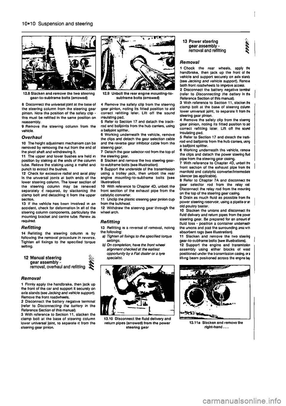
12.9 Unbolt the rear engine mountlng-to-subframe bolts (arrowed) 4 Remove the safety clip from the steering gear pinion, noting Its fitted position to aid correct refitting later. Lift off the sound insulating pad. 5 Refer to Section 17 and dotach the track* rod end bailjoints from the hub carriers, using a balljoint splitter. 6 Working underneath the vehicle, remove the clips and detach the gear selection cable and the reverse gear inhibitor cable from the steenng gear. 7 Delach the gear selector rod from the top of the steering gear, 8 Slacken and remove the two steering gear-to-subframe bolts (see Illustration) 9 Support the underside of the transmission using a trolley jack, then unbolt the rear engine mountlng-to-subframe bolts (see illustration) 10 With reference to Chapter 4D. unbolt the front section of the exhaust pipe from the catalytic converter. 11 Unclip the plastic steenng gear pinion cup from ihe bulkhead. 12 Withdraw the steenng gear through the wheel arch.
Refitting 13 Refitting is a reversal of removal, noting the following: a) Tighten all fixings lo the specified torque settings. b) On completion, have the front wheel alignment checked at the earliest opportunity by a Fiat dealer or a tyro specialist.
13.10 Disconnect the fluid delivery and return pipes (arrowed) from the power steering gear
13 Power steering * gear assembly - J removal and refitting ^
Removal 1 Chock the rear wheels, apply tN handbrake, then jack up the front ot thi vehicle and support securely on axle standi (see Jacking and vehicle support). Remove both front roadwheels to improve access. 2 Disconnect the battery negative terminal (refer to Disconnecting the battery In tto Reference Section of this manual). 3 With reforence to Section 11, slacken ihe clamp bolt at the base of steering cohimn lower universal joint, to separate ll from Ihe steering gear pinion. 4 Remove the safety clip from the steenng gear pinion, noting its fitted position lo aid correct refitting later. Lift off the sound Insulating pad. 5 Refer to Section 17 and detach the track-rod end bailjoints from the hub carriers, usty a balljoint splitter. 6 Working underneath the vehicle, ranwvi the clips and detach the power steering fluid pipe from the steering gear casing. 7 With reference to Chapter 40, unboil lbs front section of the exhaust pipe from the manifold and catalytic converter/intermediate silencer (as applicable). 8 Refer to Chaptor 7A and disconnect the gear selector rod from the relay rod Disconnect the relay rod from the mounting on the top of the steering gear casing. 9 Drain as much fluid as possible from the power steering reservoir, using a pipette or
an
old poultry baster. 10 Slacken the unions and disconnect the fluid delivery and return pipes from the power steering gear. Be prepared for an amount
erf
fluid loss - position a container underneath the unions and pad the surrounding area wth absorbent rags (see Illustration). 11 Slacken and remove the two sleeting gear-to-subframe bolts (see illustrations). 12 Support the engine and tronsmission assembly using either blocks of wood positioned under the transmission casing,
or a
lifting beam positioned across the engine
bay
13.11a Slacken and remove the right-hand...
Page 214 of 225
10*1
Chapter 12
Body electrical systems
Contents
Bulbs (exterior lights) - renewal 4 Bulbs (interior lights) - renewal 5 Electrical fault finding - general information 2 Exterior light units - removal and refitting 6 Fuses and relays - general Information 3 General information and precautions 1 Headlight beam alignment • general Information 6 Horn • removal and refitting 9 Instrument panel - removal and refitting 7 Loudspeakers - removal and refitting 10
Degrees of difficulty
Radio aerial - removal and refitting 11 Radio/cassette player • removal and refitting 12 Speedometer drive cable - removal and refitting 13 Switches - removal end refitting 14 Tailgate wiper motor - removal and refitting 15 Windscreen wiper motor - removal and refitting 17 Windscreen/tailgate washer system components • removal and refitting 16 Wiper arm • removal and refitting 18
Easy,
statable for ^
novice with liffle
|| experience ^
Fairly
easy,
suitable for beginner with ^ some experience ^
Fabtycffficiit,
suitable
for competent ^
DIY
mechanic ^
Difficult, suitable for
^ experienced DIY JR mechanic
Very difficult,
A,
suitable
for
expert DIY
Sj or professional ^
Specifications
Bulb ratings Watts Headlights 60/55 Front long range driving light 55 Front fogllght 55 Front direction Indicator light 21 Front sidelight 5 Front direction indicator repeater light 5 Stop light 21 Tall light 5 Rear direction indicator light 21 Reversing light 21 near fogllght 21 Hear number plate light 5 Courtesy light 10 Map reading light 5
1 Genera! information and precautions
A
Warning: fie/Ore carrying out any work on the electrical system, read through the precautions given in Safety first! at the beginning of this manual, and in Chapter 8. The electrical system is of 12-volt negative earth type. Power for the lights and all electrical accessories is supplied by a lead/acid type battery, which is charged by the alternator. This Chapter covers repair and service procedures for the various electrical components not associated with the engine. Information on the battery, alternator and starter motor can be found in Chapter 5. It should be noted that, prior to working on any component In the electrical system, the
battery negative terminal should first be disconnected, to prevent the possibility of electrical short-circuits and/or fires. Caution: Before proceeding, refer to Disconnecting the battery In the Reference Section of this manual for further information.
2 Electrical fault finding-general information
Note: Refer to the precautions given In Safety first! and in Section 1 of this Chapter before starting work. The following tests relate to testing ot the main electrical circuits, and should not be used to test delicate electronic circuits (such as antHock braking systems), particularly where an electronic con fro/ module is used.
General 1 A typical electrical circuit consists of an electrical component, any switches, relays, motors, fuses, fusible links or circuit breakers related to that component, and the wiring and connectors which link the component to both the battery and the chassis. To help to pinpoint a problem in an electrical circuit, wiring diagrams are Included at the end of this manual. 2 Before attempting to diagnose an electrical fault, first study the appropriate wiring diagram, to obtain a more complete understanding of the components included In the particular circuit concerned. The possible sources of a fault can be narrowed down by noting whether other components related to the circuit are operating properly. If several components or circuits fait at one time, the problem Is likely to be related to a shared fuse or earth connection.
Page 215 of 225
12*2 Body electrical systems
3 Electrical problems usually stem from simple causes, such as loose or corroded connections, a faulty earth connection, a blown fuse, a melted lusible link, or a fautty relay {refer to Section 3 for details of testing relays). Visually inspect the condition of all (uses, wires and connections in a problem circuit before testing the components. Use the wiring diagrams lo determine which terminal connections will need to be checked, in order to pinpoint the trouble-spot. 4 The basic tools required for electrical fault-finding include a circuit tester or voltmeter (a 12-volt bulb with a set of lest leads can also be used for certain tests}; a self-powered test light (sometimes known as a continuity tester); an ohmmeter (to measure resistance): a battery and set of tesi leads: and a lumper wire, preferably with u circuit breaker or fuse incorporated, which can be used to bypass susoect wires or electrical components. Before attempting to locate a problem with tost instruments, use the wiring diagram to determine where to make the connections. 5 To find the source of an intermittent wiring fault (usually due to a poor or dirty connection, or damaged wiring Insulation), a wiggle test can be performed on the wiring. This involves wiggling the wiring by hand, to see if tha fault occurs as the wiring Is moved. It should be possible to narrow down the source of the fault to a particular section of wiring. This method of testing can be used in conjunction with any of the tests descnbed in the following sub-Sections. 6 Apart from problems due to poor connections, two basic types of fault can occur in an electrical circuit - open-circuit, or short-circuit. 7 Open-circuit faults are caused by a break somewhere in the circuit, which prevents current from flowing. An open-circuit fault will prevent a component from working, but will not cause the relevant circuit fuse to blow 8 Short-circuit faults are caused by a shod somewhere in the circuit, which allows Die current flowing In the circuit to escape along an alternative route, usually to earth. Short-circuit faults are normally caused by a breakdown in wiring insulation, which allows a feed wire to touch either another wire, or an earthed component such as the bodysheli. A short-circuit fault will normally cause the relevant circuit fuse to blow.
Finding an open-circuit 9 To check for an opon-circuit, connect one lead of a circuit tester or voltmoter to either the negative battery terminal or a known good earth. 10 Connect the other lead to a connector in the circuit being tested, preferably nearest to the batter/ or luse. 11 Switch on the circuit, bearing In mind that some circuits are live only when tho ignition switch is moved to a particular position. 12 If voltage is present (Indicated either by
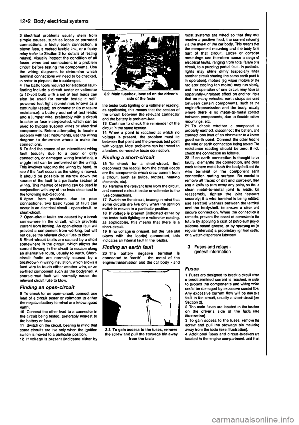
3.2 Main fuse box, located on the driver's side of the facie the toster bulb lighting or a voltmeter reading, as applicable), this means that tho section of Ihe circuit between the relevant connector and the battery is problem-free. 13 Continue to check the remainder ot the circuit in the same fashion. 14 When a point is reached at which no voltage Is present, the problem must lie between that point and the previous test point with voltage. Most problems can be traced to a broken, corroded or loose connection.
Finding a short-circuit 15 To check for a short-circuit, first disconnect the load(s) from the circuit (loads are the components which draw current from a circuit, such as bulbs, motors, heating elements, etc). 16 Remove the relevant luse Irom the circuit, and connect a circuit tester or voltmeter to the luse connections. 17 Switch on the circuit, beanng in mind that some circuits are live only when the ignition switch is moved to a particular position. 18 If voltage is present (indicated either by the tester bulb lighting or a voltmeter reading, as applicable), this means that there Is a short-circuit. 19 If no voltage is present, but the fuse still blows with the load(s) connected, this indicates an internal fault in the load(s).
Finding an earth fault 20 The battery negative terminal Is connected to 'earth' - the metal of the engine/transmission and the car body - and
I
IK
J 3.3 To gain access to the fuses, remove the screw and pull the stowage bin away from the facia
most systems are wired so that they only receive a positive feed, the current returning via the metal of Ihe car body. This means that the component mounting and the body form part of that circuit. Loose or corroded mountings can therefore cause a range of electrical faults, ranging from total failure ot a circuit, to a puzzling partial fault. In particular, lights may shine dimly (especially when another circuit sharing the same earth port In operation), motors (eg wiper motors v Ihe radiator cooling fan motor) may run slowly, and Ihe operation of one circuit may have an apparently-unrelated effect on another. Ncie that on many vehicles, earth straps axe uses between certain components, such as the engine/transmission and the body, usually whore there is no metal-to-metal contact between components, due to flexible rubber mountings, etc. 21 To check whether a component $ properly earthed, disconnect Ihe battery, and connect one lead of an ohmmeter to a kwwi good earth point. Connect the other lead to the wire or earth connection being tested. Tha resistance reading should be zero; if not. check the connection as follows. 22 If an earth connection Is thought to be faulty, dismantle the connection, and clean pack to bare metal both the bodysheli and ite wire terminal or the component earth connection mating surface. Be careful to remove all traces of dirt and corrosion, then use a knife to trim away any palm, so thai a clean metal-to-metal joint Is mads. On reassemoly, tighten the joint fasteners securely: if a wire terminal Is being refitted, use serrated washers between tho terminal and the bodysheli. to ensure a clean and secure connection. When the connection is remade, prevent the onset ot corrosion in the future by applying a coat of petroleum idly
or
stlicone-based grease, or by spraying on (a: regular intervals} a proprietary ignition eoater, or a water-aispersant lubneant.
3 Fuses and relays -general information
Fuses 1 Fuses are designod to break a circuit when a predetermined current is reached, in order to protect the components and wiring wttioh could be damaged by excessive current How. Any excessive current flow will be due to a fault in the circuit, usually a short-circuit (see Section 2). 2 The main fuses are located in the fusefcox on the driver's side of the facia (see illustration). 3 To gain access to the fuses, remove tne screw and pull the stowage bin moulding away from the facia (see illustration). 4 Additional fuses and circuit-breakers are located In the engine compartment, and in an