Torque settings FIAT PUNTO 1998 176 / 1.G Owner's Manual
[x] Cancel search | Manufacturer: FIAT, Model Year: 1998, Model line: PUNTO, Model: FIAT PUNTO 1998 176 / 1.GPages: 225, PDF Size: 18.54 MB
Page 189 of 225
10*1
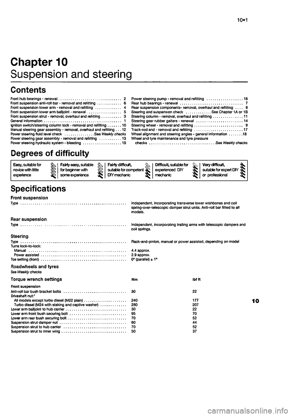
Chapter 10
Suspension and steering
Contents
Front hub bearings - renewal 2 Front suspension anti-roll bar • removal and refitting 6 Front suspension lower arm - removal and refitting 4 Front suspension lower arm balljolnt - renewal 5 From suspension strut - removal, overhaul and refitting 3 General information 1 Ignition switch/steering column lock - removal and refitting 10 Manual steering gear assembly - removal, overhaul and refitting ... 12 Power steering fluid level check See Weekly checks Power steering gear assembly - removal and refitting 13 Power steering hydraulic system - bleeding 15
Degrees of difficulty
Power steering pump • removal and refitting 16 Rear hub bearings - renewal 7 Rear suspension components- removal, overhaul and refitting 8 Steering and suspension check See Chapter 1A or 1B Steering column - removal, overhaul and refitting 11 Steering gear rubber gaiters - renewal 14 Steering wheel - removal and refitting 9 Track-rod end - removal and refitting 17 Wheel alignment and steering angles • general information 18 Wheel and tyre maintenance and tyre pressure checks See Weekly checks
Easy, suitable for nowoe with little
Jg experience ^
Fakty easy,
suitable for beginner
with
J£>
some experience
^
FaMy difficult,
% suitable for competent ^
DIY mechanic
^
Difficult,
suitable for & experienced DIY « mechsmc ^
Very difficult,
^ suitable for expert
DIY
fij or professional ^
Specifications
Front suspension Type
Rear suspension Type
Steering Type Turns lock-to-lock: Manual Power assisted Toe setting (front)
Roadwheeis and tyres See Weekly checks
Torque wrench settings Front suspension Anti-roll bar bush bracket bolts Driveshaft nut:' All models except turbo diesel (M22 plain) Turbo diesel (M24 with staking and captive washer) Lower arm balljoint to hub carrier Lower arm front bush securing bolt Lower arm rear bush securing bolt Suspension strut damper nut Suspension strut to hub carrier Suspension strut to inner wing
Independent, incorporating transverse lower wishbones and coil spring-over-teiescopic damper strut units. Anti-roll bar fitted to all models.
Independent, incorporating trailing arms with telescopic dampers and coil springs.
Rack-and-pinlon, manual or power assisted, depending on model
4.4 approx. 2.9 approx. 0° (parallel) ± 1a
Nm ibfft
30 22
240 177 280 207 30 22 95 70 70 52 60 44 70 52 50 37
Page 190 of 225
Suspension and steering 10*2
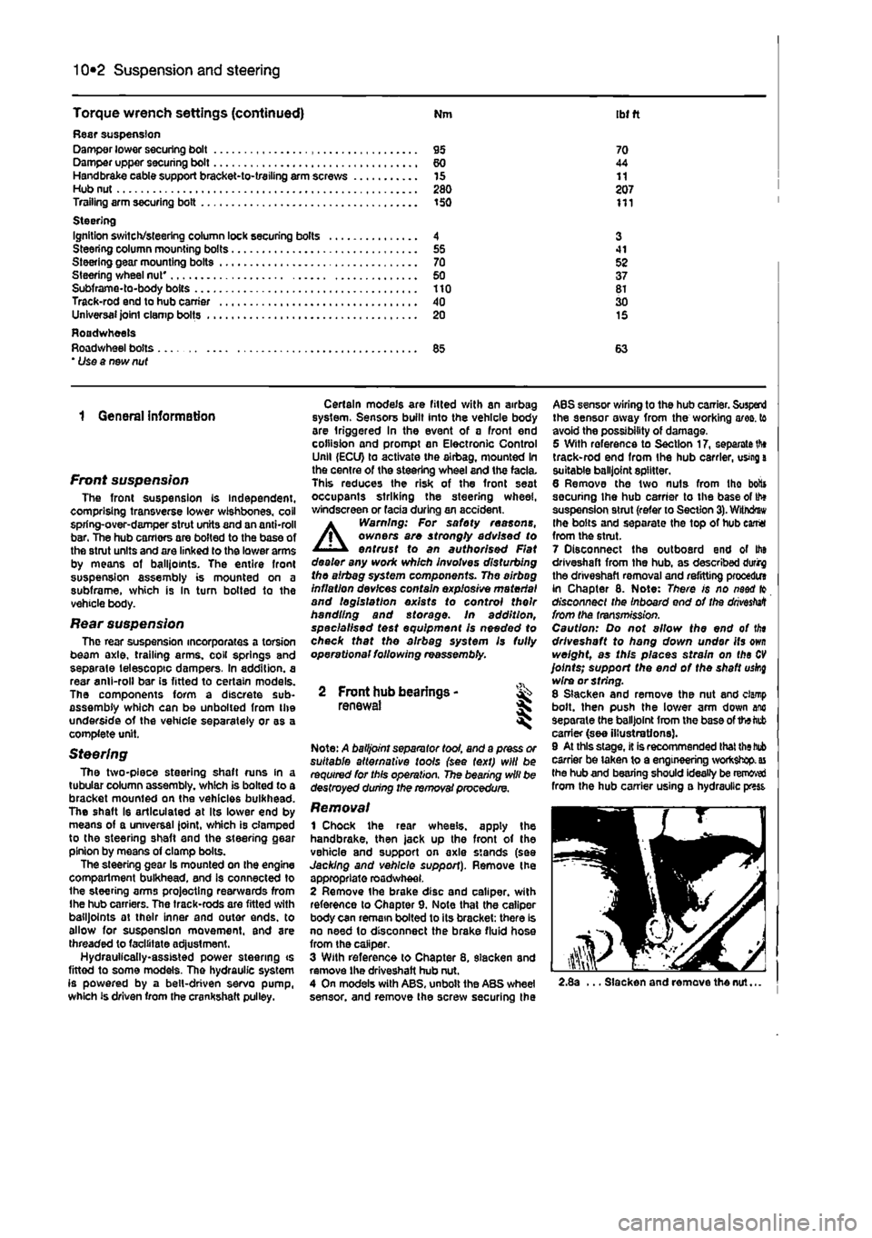
Torque wrench settings (continued) Nm ibt ft Rasr suspension Damper lower securing bolt 95 70 Damper upper securing bolt 60 44 Handbrake cable support bracket-to-trailing arm screws 15 11 Hub nut 280 207 Trailing arm securing bolt 150 111 Steering Ignition switch/steering column lock securing bolts 4 3 Steering column mounting bolts 55 41 Steering gear mounting bolts 70 52 Steering wheel nut' 50 37 Subframe-to-body bolts 110 81 Track-rod end to hub carrier 40 30 Unlversaijointclampbolts 20 15 Roadwheels Roadwheel bolts 85 63 * Use a new nut
1 General information
Front suspension The front suspension is independent, comprising transverse lower wishbones, coil spring-over-damper strut units and an anti-roll bar. The hub carriors are bolted to the base of the stmt units and are linked to the lower arms by means ot balliotnts. The entire front suspension assembly is mounted on a subframe, which is In turn botted to the vehicle body.
Rear suspension The rear suspension incorporates a torsion beam axle, trailing arms, coil springs and separate telescopic dampers. In addition, a rear anil-roll bar is fitted to certain models. The components form a discrete sub-assembly which can be unboiled from the underside of the vehicle separately or as a complete unit.
Steering The two-piece steering shaft runs in a tubular column assembly, which is bolted to a bracket mounted on the vehicles bulkhead. The shaft Is articulated at its lower end by means of a universal Joint, which is clamped to the steering shaft and the steering gear pinion by moans of clamp bolts. The steering gear is mounted on the engine compartment bulkhead, and is connected to the steering arms projecting rearwards from Ihe hub carriers. The track-rods are fitted with balljoints at their inner and outer ends, to allow for suspension movement, and are threaded to facilitate ad|ustment. Hydrauiically-assisted power steering ts fittod to some models. The hydraulic system is powered by a belt-driven servo pump, which is driven from the crankshaft pulley.
Certain models are fitted with an airbag system. Sensors built into the vehicle body are triggered in the event of a front end collision and prompt an Electronic Control Unll (ECU) to activate the airbag, mounted In the centre of the steering wheel and the facia. This reduces the risk of the front seat occupants striking the steering wheel, windscreen or facia during an accident.
A
Warning: For safety reasons, owners are strongty advised to entrust to an authorised Flat dealer any work which involves disturbing the airbag system components. The airbag inflation devices contain explosive material and legislation exists to control their handling and storage, in addition, specialised test equipment Is needed to check that the airbag system Is fully operational following reassembly.
2 Front hub bearings -renewal *
Note: A balljoint separator tool, and a press or suitable alternative tools (see text) will be required for this operation. The bearing will be destroyed during the removal procedure.
Removal 1 Chock the rear wheels, apply the handbrake, then jack up the front of the vehicle and support on axle stands (see Jacking and vehicle support). Remove the appropriate roadwheel. 2 Remove the brake disc and caliper, with reference to Chapter 9. Note that the caliper body can remain bolted to its bracket: there is no need lo disconnect the brake fluid hose from the caliper. 3 With reference to Chapter 8. slacken and remove the driveshaft hub nut. 4 On models with ABS, unbolt the ABS wheel sensor, and remove the screw securing the
ABS sensor wiring to the hub carrier. Suspend the sensor away from the working ares, to avoid the possibility of damage. 5 With reference to Section 17, separate
th»
track-rod end from the hub carrier, using
a
suitable balljoint splitter. 6 Remove the two nuts from tho botts securing Ihe hub carrier to the base of th» suspension strut (refer to Section
3).
Withdrew the bolts and separate the top of hub earrtt from the strut. 7 Disconnect the outboard end of Ito driveshaft from the hub, as described durirg the driveshaft removal and refitting procedm in Chapter 8. Note: There is no naod fo disconnect the Inboard end of the
drivestett
from the transmission. Caution: Do not allow the end of tin driveshaft to hang down under its
own
weight, as this places strain on the
CV
joints; support the end of the shaft uskg wire or string. 8 Slacken and remove the nut and clamp bolt, then push the lower arm down anc separate the balljoint from the base of the tab carrier (see illustrations). 9 At this stage, it is recommended that
the bub
carrier be taken to a engineering workshop,
as
the hub and bearing should ideally be removed from the hub carrier using a hydraulic press
2.8a ... Slacken and remove the nut...
Page 196 of 225
Suspension and steering 10*8
9.1 Prise the horn centre pad from the steering wheel hub unbolt the lower end of the damper from the trailing arm. 9 Lower the trailing arm gradually using a trolley jack, until the coil spring Is released from its lower seat on the trailing arm and its upper seat on the subframe. Make a note of the orientation of the coll spring, to aid correct refitting later. Refitting 10 Refitting is a reversal of removal, lighten the damper lower retaining bolt to the specified torque. Trailing arm Note: The rear stub axles are integral with the trailing arm assemblies and cannot be renewed separately. Removal 11 With reference to Chapter 9. carry out the following: a) Remove the brake drum, shoes and adjuster assembly. b) Unbolt the brake hose union from the
rear
of the wheel cylinder. c) Unbolt the brake pipe mounting bracket from the trailing arm. 12 Refer to Section 7 and remove The rear hub and beanng assembly. 13 With reference to the relevant sub-Section, unbolt the lower end of Ihe damper from the trailing arm. 14 Raise the trailing arm using a trolley jack so that the coll spring Is compressed, then slacken and withdraw the trailing arm front mounting bolL 15 With reference to the previous sub-Section, gradually lower the trailing arm using a trolley lack and remove the coll spring. 16 Allow Ihe trailing arm to hang down, then pull the leading edge of the arm down from its mounting bracket. Refitting 17 Refitting Is a reversal of removal. Tighten all suspension fixings to the specified torque settings, but delay this operation until the full weight vehicle is resting on the roadwheeis -this prevents the damper and trailing arm bushes from being strained. 18 On completion, bleed the brake hydraulic system and adjust the operation of the handbrake, with reference to Chapter 9.
9.2 Unplug the wiring from the centre pad at the connector(s)
9 Steering wheel - % removal and refitting ^
Note: This procedure does not apply to vehicles fitted with an airbag A Warning: For safety reasons, owners are strongly advisod to entrust to an authorised Fiat dealer any work which involves disturbing the airbeg system components. The airbag inflation devices contain explosive material and legislation exists to control their handling and storage. In addition, specialised test equipment Is needed to check thet the alrbag system Is fully operational following reassembly.
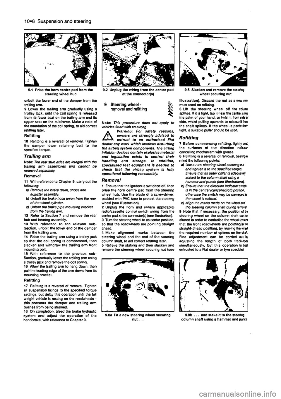
Removal 1 Ensure that the ignition is switched off, then prise the horn centre pad from the steering wheel hub. Use the blade of a screwdriver, padded with PVC tape to protect the steering wheel (see illustration) 2 Unplug the horn and (where applicable) radio/cassette control switch wiring from the centre pad at the connectors) (see illustration) 3 Turn the steering wheel to its centre position, so that the roadwheeis are pointing straight ahead. 4 Make alignment marks between the steering wheel and the end of the steering column shaft, to aid correct refitting later, 5 Relieve the staking and then slacken and remove tne steenng wheel securing nut (see
9.5 Slacken and remove the steering wheel securing nut Illustration). Discard the nut as a new item must used on refitting. 6 Lift the steering wheel off the column splines. If it is tight, tap il near the centre, usrg the palm of your hand, or twist it from
side to
side, whilst pulling upwards to release il ton the shaft splines. If the wheel is particular tight, a suitable puller should be used.
Refitting 7 Before commencing refitting, lightly eca. Ihe surfaces of the direction indicator cancelling mechanism with grease. 8 Refitting is a reversal of ren>oval.
bearing a
mind the following points: a) Use a new steering wheel
securing not
and tighten it to the specified
torque.
Ensure that its outer collar
Is adequate^
staked to the column shaft
using a
hammer and punch (see Illustrations). b) Ensure that the direction Indicator
swiith
is in the central (cancelled/off)
position,
otherv/ise the sivitch may be damaged X the wheel Is refitted. c) Align the marks made on the
wheel and
Ihe steering column shaft during removeI 9 Note that if necessary, the position of tf* steering wheel on the column shaft cant* | altered in order to centralise the wheel (enstn that the front roadwheeis aro pointing
In the
straight-ahead position), by moving the vMti the required number of splines on the
sfcafc
Fine adjustment can be carried out by adjusting the length of both track-rwa simultaneously, but this operation is best entrusted to a Rat dealer or tyre specialist
9.8a Fit a new steering wheet securing nut... 9.3b ... and stake it to the steering column shaft using o hammer and punch
Page 198 of 225
10*10 Suspension and steering
12.8 Slacken and remove the two steering goar-to-subirame bolts (arrowed) 8 Disconnect the universal joint at the base of the steering column from the steering gear pinion. Note the position of tho safety clip • this must be refitted In the same position on reassembly. 9 Remove Ihe steering column from the vehicle.
Overhaul 10 The hoight adjustment mechanism can be removed by removing the nut from the end of the pivot shaft and withdrawing it. 11 The upper and lower bushes are held in position by staking at the ends of the column tube. Relieve the staking using a mallet and punch to extract the bushes. 12 Check for excessive radial and axial play In the universal joints at both ends of the lower steering column. The lower section of the steering column may be renewed separately if required, by slackening the clamp bolt and detaching It from the upper section. 13 If the vehicle has been Involved in an accident, check for deformation In all ol the steering column components, particularly the mounting bracket and centre tube. Renew as required.
Refitting 14 Refitting the steering column is by following the removal procedure in reverse. Tighten all fixings to Ihe specified torque setting.
12 ManuaJ steering fk gear assembly -removal, overhaul and refitting
Removal 1 Firmly apply the handbrake, then jack up the front of the car and support it securely on axie stands (see Jacking and vehicle support). Remove the front road wheels. 2 Disconnect the battery negative terminal (refer to Disconnecting the battery in the Reference Section of this manual). 3 With reference to Section 11. slacken the clamp boil at the base of steering column lower universal |o!nt, to separate it rrom the steering gear pinion.
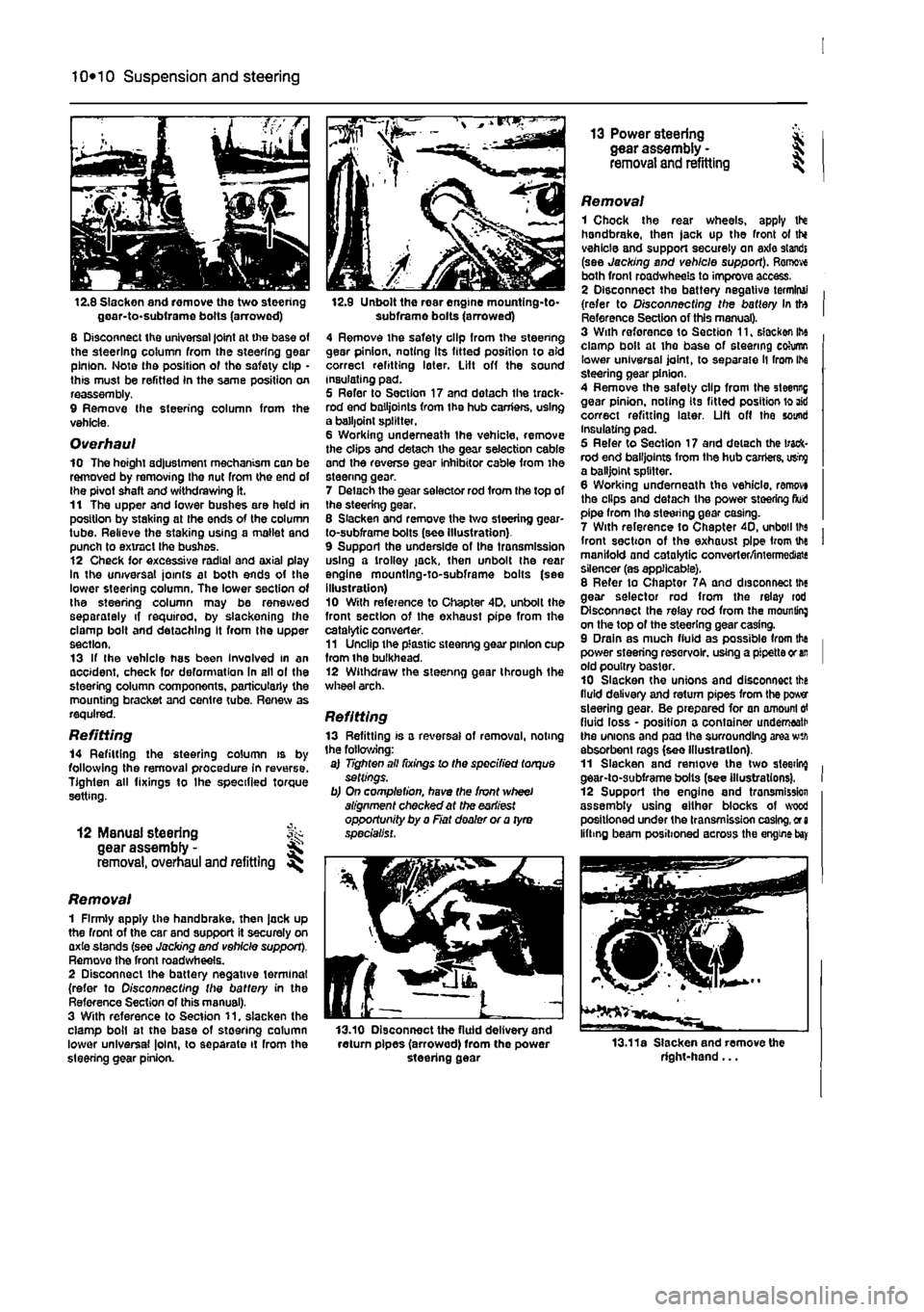
12.9 Unbolt the rear engine mountlng-to-subframe bolts (arrowed) 4 Remove the safety clip from the steering gear pinion, noting Its fitted position to aid correct refitting later. Lift off the sound insulating pad. 5 Refer to Section 17 and dotach the track* rod end bailjoints from the hub carriers, using a balljoint splitter. 6 Working underneath the vehicle, remove the clips and detach the gear selection cable and the reverse gear inhibitor cable from the steenng gear. 7 Delach the gear selector rod from the top of the steering gear, 8 Slacken and remove the two steering gear-to-subframe bolts (see Illustration) 9 Support the underside of the transmission using a trolley jack, then unbolt the rear engine mountlng-to-subframe bolts (see illustration) 10 With reference to Chapter 4D. unbolt the front section of the exhaust pipe from the catalytic converter. 11 Unclip the plastic steenng gear pinion cup from ihe bulkhead. 12 Withdraw the steenng gear through the wheel arch.
Refitting 13 Refitting is a reversal of removal, noting the following: a) Tighten all fixings lo the specified torque settings. b) On completion, have the front wheel alignment checked at the earliest opportunity by a Fiat dealer or a tyro specialist.
13.10 Disconnect the fluid delivery and return pipes (arrowed) from the power steering gear
13 Power steering * gear assembly - J removal and refitting ^
Removal 1 Chock the rear wheels, apply tN handbrake, then jack up the front ot thi vehicle and support securely on axle standi (see Jacking and vehicle support). Remove both front roadwheels to improve access. 2 Disconnect the battery negative terminal (refer to Disconnecting the battery In tto Reference Section of this manual). 3 With reforence to Section 11, slacken ihe clamp bolt at the base of steering cohimn lower universal joint, to separate ll from Ihe steering gear pinion. 4 Remove the safety clip from the steenng gear pinion, noting its fitted position lo aid correct refitting later. Lift off the sound Insulating pad. 5 Refer to Section 17 and detach the track-rod end bailjoints from the hub carriers, usty a balljoint splitter. 6 Working underneath the vehicle, ranwvi the clips and detach the power steering fluid pipe from the steering gear casing. 7 With reference to Chapter 40, unboil lbs front section of the exhaust pipe from the manifold and catalytic converter/intermediate silencer (as applicable). 8 Refer to Chaptor 7A and disconnect the gear selector rod from the relay rod Disconnect the relay rod from the mounting on the top of the steering gear casing. 9 Drain as much fluid as possible from the power steering reservoir, using a pipette or
an
old poultry baster. 10 Slacken the unions and disconnect the fluid delivery and return pipes from the power steering gear. Be prepared for an amount
erf
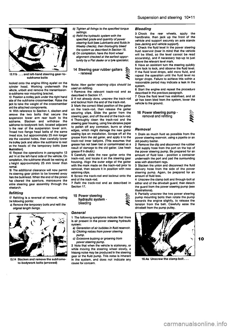
fluid loss - position a container underneath the unions and pad the surrounding area wth absorbent rags (see Illustration). 11 Slacken and remove the two sleeting gear-to-subframe bolts (see illustrations). 12 Support the engine and tronsmission assembly using either blocks of wood positioned under the transmission casing,
or a
lifting beam positioned across the engine
bay
13.11a Slacken and remove the right-hand...
Page 199 of 225
Suspension and steering 10*11
13.11b ... and left-hand steering gear-to-subframe bolts
hooked onto the engine lifting eyelet on the cylinder head. Working underneath the vehicle, unbolt and remove the transmission-lo-subframe rear mounting bracket. 13 Position a trolley jack under the right hand skle of the subframe crossmember. Raise the jack to take the weight of the crossmember
and
the attached components. 14 With reference to Section 4, slacken and remove the two bolts that secure the suspension lower arm rear bush to the subframe. Slacken and withdraw the subframe-to-bodywork bolt, located adjacent to the rear of the suspension lower arm. Throad two flange head bolts of the same thread size, but approximately 25 mm longer into the vacated holes, then carefully lower
the
trolley jack and allow ihe subframe to rest on the heads of the temporary bolts (see (lustration), 15 Repeat the operations in paragraphs 13 end 14 at the left-hand side of the vehicle. On completion, the subframe should be resting at
&
height approximately 25 mm lower than normal. 16 The additional clearance will now permit the steering gear pinion to be lowered away from the bulkhead. When the end of the pinion has cleared Ihe aperture, manoeuvre the entire steering gear assembly through the *tiae?arch.
Refitting 17 Refitting is a reversal of removal, noting
the
following points: s) Remote the temporary bolts and refit the original length fixings.
13.14 Slacken and remove the subframe-to-bodywork bolts (arrowed)
b) Tighten all fixings to the specified torque settings. c) Refill the hydraulic system with the specified grade and quantity of power steering fluid (see Lubricants and fluids In Weekly checks), then thoroughly bleed the system as described in Section 15. d) On completion, have the front wheel alignment checked at the earliest oppor-tunity by a Flat dealer or a tyre specialist.
14 Steering gear rubber gaiters - renewal <
Note: New gaiter retaining clips should be used on refitting. 1 Remove the relevant track-rod end as described in Section 17. 2 If not already done, unscresv the track-rod end locknut from Ihe end of the track-rod. 3 Mark the correct fitted position of the gaiter on the track-rod, then release the gaiter securing clips. Slide the gailer from the steering gear, and off the end of the track-rod. 4 Thoroughly clean tho track-rod and the steering gear housing, usrng fine abrasive paper to polish off any corrosion, burrs or sharp edges, which might damage the new gaiter sealing lips on installation. Scrape off all the grease from the old gaiter, and apply it to the track-rod inner balljoint. (This assumes that grease has not been lost or contaminated as a result of damage to the old gaiter. Use fresh crease if In doubt.) 5 Carefully slide the new gaiter onto the track-rod. and locate it on the steering gear housing. Align the outer edge of the gaiter with the mark made on the track-rod prior to removal, then secure it in position with new retaining clips. 6 Screw the track-rod end locknut onto the end of the track-rod. 7 Refit the track-rod end as described in Section 17.
15 Power steering hydraulic system • bleeding ^
General 1 The following symptoms indicate that there is air present In the power steering hydraulic system: a) Generation of air bubbles in fluid reservoir. b) Clicking noises from power steering pump. c) Excessive buzzing or groaning from power steering pump. 2 Note that when the vehicle Is stationary, or while moving the steering wheel slowly, a hissing noise may be produced In the steering gear or the fluid pump. This noise is inherent in the system, and does not indicate any cause for concern.
Bleeding 3 Chock the rear wheels, apply the handbrake, then jack up the front of the vehicle and support securely on axle stands (see Jacking and vehicle support). 4 Check the fluid level in the power steering fluid reservoir (bear in mind that the vehicle will be tilted, so the level cannot be read accurately), and if necessary top-up to just above the relevant level mark. 5 Have an assistant tum the steering quickly from lock to lock, and observe tho fluid level, if the fluid level drops, add more fluid, and repeat the operation until the fluid level no longer drops. Failure to achieve this within a reasonable period may indicate a leak in the system. 6 Stan the engine and repeat the procedure described In the previous paragraph. 7 Once the fluid level has stabilised, and all air has been bled from the system, lower the vehicle to the ground.
16 Power steering pump - Sk removal and refitting ^
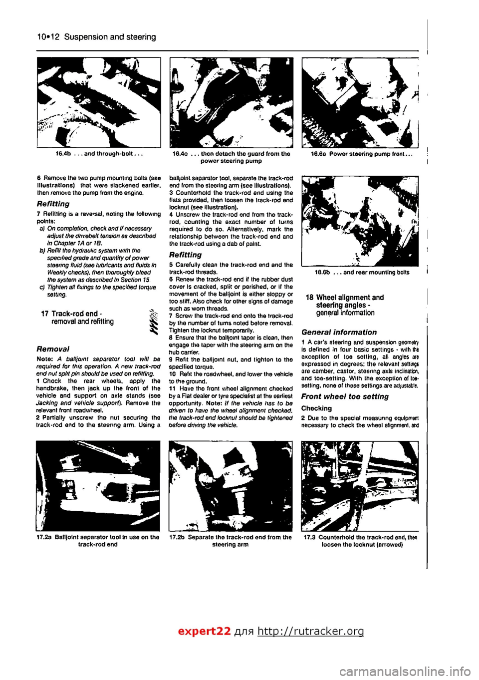
Removal 1 Drain as much fluid as possible from the power steering reservoir, using a pipette or an old poultry baster. 2 Remove the clip and disconnect the rubber fluid supply hose from the port on the top of the power steering pump. Be prepared for an amount of fluid loss • position a container underneath the port and pad the surrounding area with absorbent rags. 3 Slacken the union and disconnect the fluid delivery hose from the side of the power steering pump. Again, be prepared for an amount of fluid loss. 4 Unscrew tho clamp bolt and through-bolt at either end of the drivebelt guard, then detach Ihe guard from the power steering pump (see illustrations). 5 Partially unscresv the two power steering pump mounting bolts then rotate the pump towards the engine slightly, to release the tension from the belt. Carefully ease the drivebelt from the pump pulley.
16.4a Unscrew the clamp bolt...
Page 200 of 225
10*12 Suspension and steering
16.4b ... and through-bolt...
6 Remove the two pump mounting bolts (see Illustrations) that were slackened earlier, then remove the pump from the engine.
Refitting 7 Refilling is a reversal, noting the following points: a) On completion, check and j? necessary adjust the dm'ebelt tension ay described In Chapter JA or IB. b) Refill the hydraulic system with the specified grade and quantity of power steering fluid (sw lubricants and fluids in Weekly checks), then thoroughly bleed the system as described In Section 15. c) Tighten all fixings to the specified torque setting,
17 Track-rod end -removal and refitting ^ S
Removal Note: A ball joint separator tool will do required for this operation. A new track-rod end nut split pin should be used on refitting. 1 Chock the rear wheels, apply the handbrake,
I
hen jack up Ihe front of the vehicle and support on axle stands (see Jacking and vehicle support). Remove the relevant front roadwheel. 2 Partially unscrew the nut securing the (rack-rod end to the steering arm. Using a
17.2a Balljoint separator tool In use on the track-rod end
16.4c ... then detach the guard from the power steering pump
ballpoint separator tool, separate Ihe track-rod end from tho steering arm (see Illustrations). 3 Counterhold the track-rod end using the flats provided, then loosen ihe irack-rod end locknut (see illustration). 4 Unscrew the track-rod end from the track-rod, counting the exact number of turns required to do so. Alternatively, mark the relationship between the track-rod end and the trock-rod using a dab of p3lnL
Refitting 5 Carefully clean the track-rod end and the track-rod threads. 6 Renew the track-rod end if the rubber dust cover Is cracked, split or perished, or If the movement of the balijoint is either sloppy or too stiff. Also check lor other signs of damage such as worn threads. 7 Screw the track-rod end onto ihe track-rod by ihe number ol turns noted before removal. Tighten the locknut temporarily. 8 Ensure that Ihe balljoint taper is clean, then engage the taper wilh the steering arm on the hub carrier. 9 Refit the balljoint nut, and tighten to the specified torque. 10 Refit the roadwheel, and lower the vehicle to the ground. 11 Have tho front wheel alignment checked by a Rat dealer or tyre specialist at the earliest opportunity. Note: // the vehicle has to be driven to have the wheel alignment checked, the track-rod end locknut should be tightened before drMng the vehicle.
17.2b Separato tho track-rod end from the steering arm
18.6b ... and rear mounting bolts
18 Wheel alignment and steering angles -general information
General information 1 A car's steering and suspension geomeiry Is defined in four basic settings • with this exception of toe sotting, all angles arc expressed in degrees: the relevant setting! are camber, castor, steering axis inclination, and toe-setting. With ihe exception of toe-sett ing, none of these settings are acfjustabitf.
Front wheel toe setting
Chocking 2 Due to the special measuring equlpr
expert22 fl/m http://rutracker.org
Page 202 of 225
10*1
Chapter 11
Bodywork and fittings
Contents
Bonnet • removal and refitting 11 Bonnet lock components - removal and refitting 12 Bonnet release cable - removal and refitting 13 Door - removal and refitting 15 Door handle and lock components • removal and refitting 16 Door inner trim panel • removal and refitting 14 Electric window components • removal and refitting 18 Exterior mirror components - removal and refitting 17 Facia - removal and refitting 19 Front bumper • removal and refitting 6
General Information 1 Maintenance - bodywork and underframe 2 Maintenance - upholstery and carpets 3 Major body damage - repair 5 Minor body damage - repair 4 Rear bumper - removal and refitting 7 Seats • removal and refitting 20 Tailgate - removal and refitting 8 Tailgate lock components - removal and refitting 10 Tailgate strut - removal and refitting 9
Degrees of difficulty
Easy, suitable for
novice with littie experience ^
Fairly
easy,
suitable ^ for beginner with ^
some
experience
Fairty difficult,
^
suitable
fcr competent
DIY
mechanic ^
Difficult,
suitable (or
^ experienced DIY »R mechanic ^
Very difficult,
^
suitable
for
expert CHY
or professional ^
Specifications
! Torque wrench settings Nm ibf ft Bonnet-to-hinge botts 8 6 Door hinge-to-body bolts 35 26
1 Genera! information
The bodyshell is composed of pressed-steel sections which are welded together, although some use of structural adhesives is made. In addition, the front wings are bolted i on. ' The bonnet, door and some other panels I vulnerable to corrosion are fabricated from zinc-coated metal. A coating of anti-chip primer, applied prior to paint spraying I provides further protection. Extensive use is made of plastic materials. ' mainly In the Interior, but also in exterior components. The outer sections of the front l and rear bumpers are injection-moulded from
a
synthetic material which is very strong, and yet light. Plastic components such as wheel | arch liners are fitted to the underside of the vehicle, to improve Ihe body's resistance to I corrosion.
2 Maintenance - ^ bodywork and underframe ||
The general condition of a vehicle's bodywork is the one thing that significantly affects its value. Maintenance is easy, but needs to be regular. Neglect, particularly after minor damage, can lead quickly to further deterioration and costly repair bills. It is important also to keep watch on those parts of the vehicle not immediately visible, for instance the underside, inside all the wheel arches, and the lower part of the engine compartment. The basic maintenance routine for the bodywork is washing - preferably with a lot of water, from a hose. This will remove all the loose solids which may have stuck to the vehicle. It is important to flush these off in such a way as to prevent grit from scratching the finish. The wheel arches and underframe need washing in the same way, to remove any
accumulated mud. which will retain moisture and tend to encourage rust. Paradoxically enough, the best time to clean the underframe and wheel arches is in wet weather, when the mud is thoroughly wet and soft. In very wet weather, the underframe is usually cleaned of large accumulations automatically, and this is a good time for inspection. Periodically, except on vehicles with a wax-based underbody protective coating, it is a good idea to have the whole of the underframe of Ihe vehicle steam-cleaned, engine compartment included, so that a thorough inspection can be carried out to see what minor repairs and renovations are necessary. Steam-cleaning is available at many garages, and is necessary for the removal of the accumulation of oily grime, which sometimes is allowed to become thick In certain areas. If steam-cleaning facilities are