Motor FIAT PUNTO 1998 176 / 1.G Service Manual
[x] Cancel search | Manufacturer: FIAT, Model Year: 1998, Model line: PUNTO, Model: FIAT PUNTO 1998 176 / 1.GPages: 225, PDF Size: 18.54 MB
Page 186 of 225
9*10 Braking system
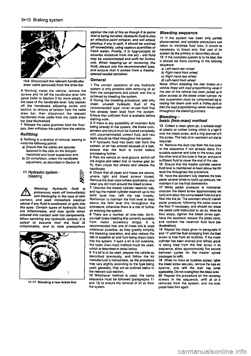
10.6 Disconnect the relevant handbrake inner cable (arrowed) from the draw bar 6 Working inside ihe vehicle, remove Ihe screws and lift off the handbrake lever trim panel (refer to Section 9 for more detail). At the base of the handbrake lever, full/ slacken off the handbrake adjusting screw and locknut, to remove oil tension from the cable draw bar, then disconnect the relevant handbrake inner cable from the cable draw bar (see illustration) 7 Release the cable grommet from tho floor-pan, then withdraw the cable from the vehicle.
Refitting 8 Refitting Is a reversal of removal, bearing in mind the following points: a) Ensure that the cables are securely fastened In the clips on the floorpan beetshield and lower suspension a/m. b) On completion, check the handbrake adiustment, as described in Section 9.
11 Hydraulic system -bleeding
A
Warning: Hydraulic fluid is poisonous; wash off immediately and thoroughly In the case ot skin contact, and seek immediate medical advice if any fluid is swallowed, or gets into the eyes. Certain types of hydraulic fluid are Inflammable, and may ignite when allowed into contact with hot components. When servicing any hydraulic system, it Is safest to assume that the fluid IS inflammable, and to take precautions
11.17 Bleeding a rear brake line
against the risk of fire as though it is petrol that Is being handled. Hydraulic fluid is also an effective paint stripper, and will attack plastics; If any is spilt, It should be washed off immediately, using copious quantities of fresh water. Finally, it Is hygroscopic (it absorbs moisture from the air) • old fluid may be contaminated and unfit tor further use. Whan topping-up or renewing the fluid, always use the recommended type, and ensure that It comes from a freshly-opened sealed container.
General 1 The correct operation of any hydraulic system is only possible after removing all air from the components and circuit; and this Is achieved by bleeding the syslem. 2 During the bleeding procedure, add only clean, unused hydraulic fluid of the recommended type; never re-use fluid that has already been bled from the system. Ensure that sufficient fluid is available before starting work. 3 If there is any possibility of incorrect fluid being already in the system, the brake com-ponents and circuit must be Flushed completely with uncontamlnated, correct fluid, and new seals should be fitted throughout the system. 4 If hydraulic fluid has been lost from the system, or air has ontered because of a leak, ensure that the fault is cured before proceeding further. 5 Park Ihe vehicle on level ground, switch off the engine and select first or reverse gear (or P), then chock the wheels and release the handbrake. 6 Cheek that all pipes and hoses are secure, unions tight and bleed screws closed. Remove Ihe dust caps (whore applicable), and clean any dirt from around the bleed screws. 7 Unscrew the master cylinder reservoir cap, and top Ihe master cylinder reservoir up to the MAX level line; refit the cap loosely. Rememoer to maintain the fluid level at least above the MIN level line throughout the procedure, otherwise there is a risk of further air entering the syslem. 8 There are a number of one-man. do-It-yourself brake bleeding kits currently available from motor accessory shops. It is recommended that one of these kits is used whenever possible, as they greatly simplify the bleeding operation, and also reduce the risk of expelled air and fluid being drawn back into the system. If such a kit is not available, the basic (two-man) method must be used, which is described in detail below. 9 If a kit Is to be used, prepare the vehicle as described previously, and follow the kit manufacturer's instructions, as Ihe procedure may vary slightly according to the type being used; generally, they are as outlined below in the relevant sub-section. 10 Whichever method is used, the same sequence must be followed (paragraphs 11 and 12) to ensure Ihe removal of all air from the system.
Bleeding sequence 11 If Ihe system has been only
partial!?
disconnected, and suitable precautions wwe taken to minimise fluid loss, it should be necessary to bteod only that part of the system (le the primary or secondary circuit). 12 If the complete system Is to be bled, then It should be done working in the following sequence: a) Left-hand rear wheel b) Right-hand front wheel. c) Right-hand rear wheel. d) Left-hand front wheel. Note: When bleeding the rear brakes
on a
vehicle ritled with load proportioning valves: i the rear of the vehicle has been jacked
up to
allow access to ihe brake wheel cylinder,
tha
rear suspension must be compressed
(eg
raising the beam axle with a trolley
jack) so
that the load proportioning valves
remain open
throughout the bleeding process.
Bleeding -basic (two~man) method 13 Collect a clean glass jar, a suitable length of plastic or rubber tubing which Is a light fit over the bleed screw, end a ring spanner lo
Rt
the screw. The help of an assistant will also tie required. 14 Remove the dust cap from the first screw In the sequence if not already done. Fit a suitable spanner and tube to the screw, place the other end of Ihe tube In the jar. and
pour in
sufficient fluid to cover the end of the tube. 15 Ensure that the master cylinder reservoir fluid level is maintained at least above the
MIN
level line throughout the procedure. 16 Have the assistant fully depress the brefce pedal several times to build up pressure, then maintain it on the final downstroke. 17 While pedal pressure is maintained, unscrew ihe bleed screw (approximately one turn) and allow the compressed fluid and orto flow into the
Jar,
The assistant should maintah pedal pressure, following the pedal down to the floor if necessary, and should not rrtaase Ihe pedal until instructed to do so. When ihe flow stops, tighten the bleed screw again, have the assistant retease the pedal sfowty, and recheck the reservoir fluid level (see Illustration). 18 Repeat Ihe steps given in paragraphs 16 end 17 until the fluid emerging from the bled screw is free from air bubbles. If Ihe master cylinder has been drained and refilled,
and
at Is being bled from the first screw In the sequence, allow approximately five seconds between cycles for the master cylinder passages to refill. 19 When no more air bubbles appear, tighter, the bleed screw securely, remove Ihe tube arc spanner, and refit the dust cap (where applicable). Do not overtighten the bleed sew. 20 Repeat the procedure on tho remaining screws In the sequence, until ail air is removed from the system, and the brake pedal feels firm again.
Page 188 of 225
9*12 Braking system
master cylinder mounting nuts, and tighten them securely. 10 Wipe clean the brake pipe unions, then refit them to the correct master cylinder ports, as noted before removal, and lighten the union nuts securely. 11 Refill tha master cylinder reservoir with new fluid, and bleed the complete hydraulic system as described In Section 11. 12 Check the operation of the braking system thoroughly.
13 Hydraulic pipes and hoses - % renewal S§
A
Warning: Before starting work, refer to the warning at the beginning of Section 11 concerning the dangers of hydraulic fluid, 1 If any pipe or hose is to be renewed, minimise fluid loss by first removing the master cylinder reservoir cap. then tighten the cap down onto a piece of polythene to obtain
an airtight seal. Alternatively, flexible hoses can be sealed, If required, using a proprietary brake hose clamp; metal brake pipe unions can be plugged (if care Is taken not to allow dirt into the system) or capped immediately they are disconnected. Place a wad of rag under any union that is to be disconnected, to catch any spilt fluid-2 If a flexible hose Is to be disconnected, unscrew the brake pipe union nut before removing the spring clip which seeurea the hose to its mounting bracket. 3 To unscrew the union nuts, ll is preferable lo obtain a brake pipe spanner of the correct size; these are available from most large molor accessory shops. Failing this, a close-fitting open-ended spanner will be required, though if the nuts are tight or corroded, their flats may be rounded-off if the spanner slips. In such a case, a self-locking wrench is often the only way to unscrew a stubborn union, but It follows that Ihe pipe and the damaged nuts must be renewed on reassembly. Always clean a union and surrounding area before disconnecting it If disconnecting a compo-
nent with more than one union, make a carefJ note of the connections before disturbing
any
of them. 4 If a brake pipe Is to be renewed, it can b« obtained, cut to length and with the union nuts and end flares in place, from Fiat dealers. All that is then necessary is to bend It to shape, following the line of the original, baton fitting It to the vehicle. Alternatively, most motor accessory shops can make up bra Ha pipes from kits, bul this requires very carefii measurement of the original, to ensure (hat the replacement is of the correct length. Tha safest answer is usually to take the original lo the shop as a pattern. 5 On refitting, do not overtighten the union nuts. It is not necessary to exercise brute force to obtain a sound joint. 6 Ensure that the pipes and hoses an correctly routed, with no kinks, and that they are secured in the clips or brackets provided. After fitting, remove the polythene from lbs reservoir, and bleed the hydraulic system
88
described In Section 11. Wash off any split fluid, and check carefully for fluid leaks.
Page 210 of 225
Bodywork and fittings
11
*9
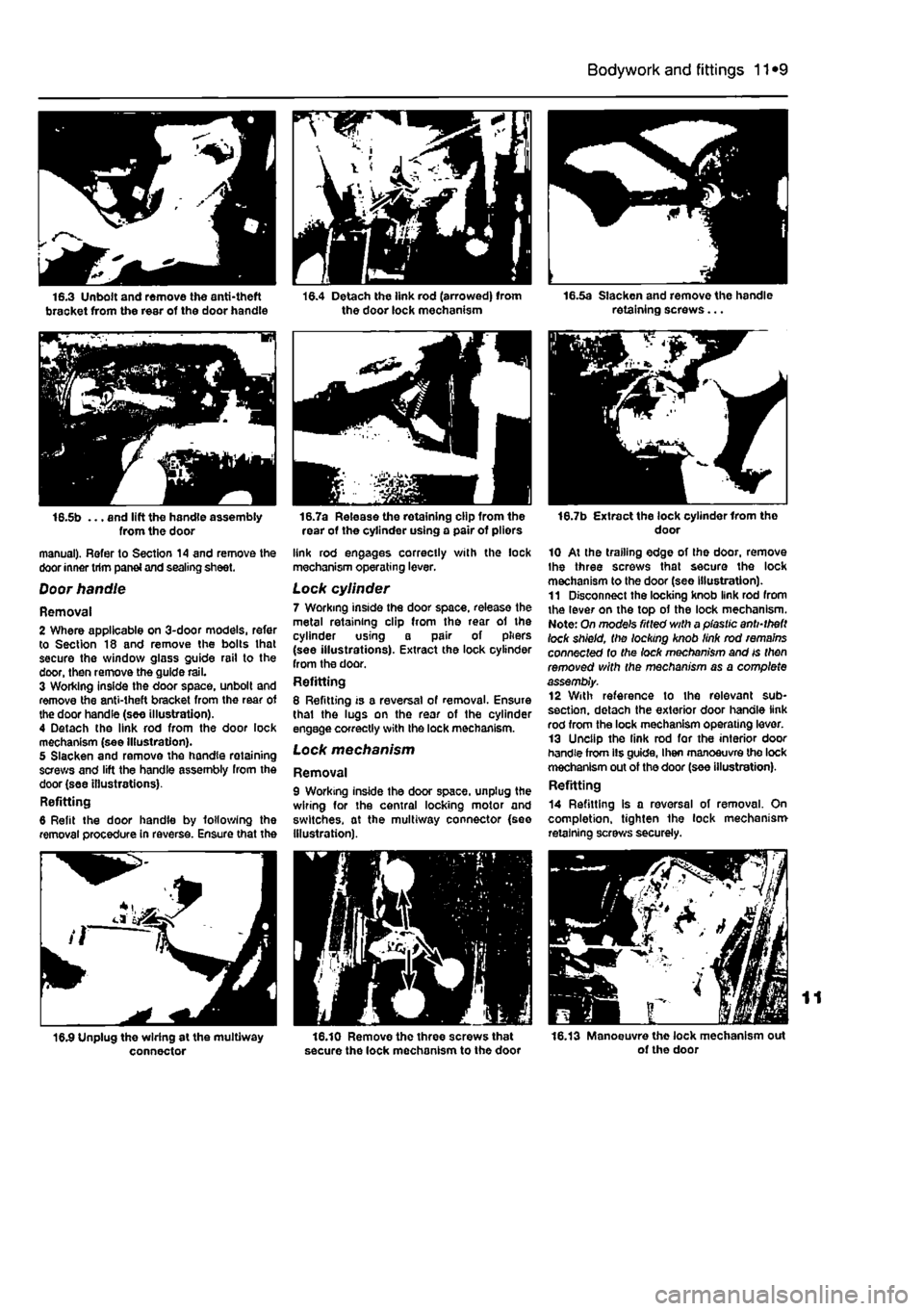
16.5b ... and lift the handle assembly from the door manual). Refer to Section 14 and remove the door inner trim panei and sealing sheet.
Door handle
Removal 2 Where applicable on 3-door models, refer to Section 18 and remove the bolts lhat secure the window glass guide rail to the door, then remove the guide rail. 3 Working inside the door space, unbolt and remove the anti-theft bracket from the rear of the door handle (see illustration). 4 Detach the link rod from the door lock mechanism (see Illustration). 5 Slacken and remove the handle retaining screws and lift the handle assembly from the door (see illustrations). Refitting 6 Refit the door handle by following the removal procedure in reverse. Ensure that the
connector
16.7a Release the retaining clip from the rear of the cylinder using a pair of pliors
link rod engages correctly with the lock mechanism operating lever.
Lock cylinder 7 Working inside the door space, release the metal retaining clip from the rear of the cylinder using a pair of pliers (see illustrations). Extract the lock cylinder from the door. Refitting 8 Refitting is a reversal of removal. Ensure thai the lugs on the rear of the cylinder engage correctly with the lock mechanism. Lock mechanism
Removal 9 Working inside the door space, unplug the wiring for the central locking motor and switches, at the multiway connector {see Illustration).
16.10 Remove the three screws that secure the lock mechanism to the door
16.7b Extract the lock cylinder Irom tho door
10 At the trailing edge of the door, remove Ihe three screws that secure the lock mechanism to the door (see Illustration). 11 Disconnect the locking knob link rod from the lever on the top of the lock mechanism. Note: On mode's fitted with a plastic anti-theft lock shield, the locking knob link rod remains connected to the lock mechanism and is then removed with the mechanism as a complete assembly. 12 With reference to the relevant sub-section. detach the exterior door handle link rod from the lock mechanism operating lever. 13 Unclip the link rod for the interior door handle from lis guide, I hen manoeuvre the lock mechanism out of the door (see illustration). Refitting
14 Refitting is a reversal of removal. On completion, tighten the lock mechanism retaining screws securely.
16.13 Manoeuvre the lock mechanism out of the door
Page 212 of 225
Bodywork and fittings
11
*11
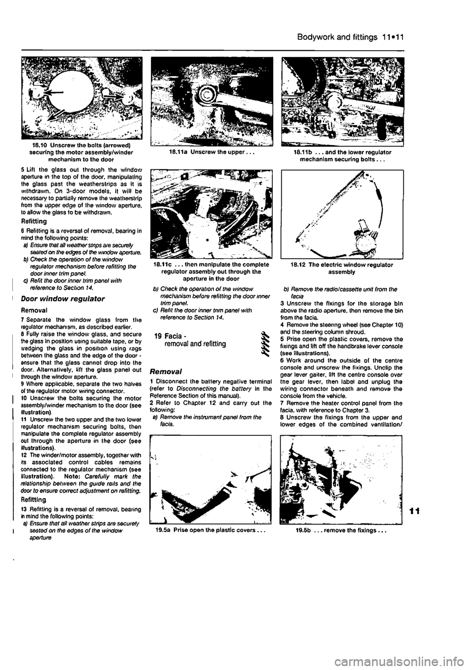
securing the motor assembly/winder mechanism to the door 5 Uft the glass out through the window aperture in the top of the door, manipulating the glass past the weatherstrips as it is withdrawn. On 3-door models, it will be necessary to partially remove the weatherstrip from the upper edge of Ihe window aperture, to allow the glass to be withdrawn. Refitting 6 Refitting is a reversal of removal, bearing in mind the following points: a) Ensure that all weather stnps are
securely
seated on the edges of the window aperture. b) Check the operation of the window regulator mechanism before refitting the door inner trim panel. | 0 Refit the door inner trim panel with | reference to Section 14.
1 Door window regulator
Removal 7 Separate the window glass from the regulator mechanism, as described earlier. 6 Fully raise the window glass, and secure the glass In position using suitable tape, or by wedging the glass in position using rags between the glass and the edge of the door • ensure that the glass cannot drop into the door. Alternatively, lift the glass panel out 1 through the window aperture. 9 Where applicable, separate the two halves of the regulator motor wiring connector. I 10 Unscrew the bolts securing the motor assembly/winder mechanism to the door (see Illustration). t1 Unscrew the two upper and the two lower regulator mechanism securing bolts, then manipulate the complete regulator assembly out through the aperture in the door (see illustrations). 12 The winder/motor assembly, together with its associated control cables remains connected to the regulator mechanism (see Illustration), Note: Carefully mark the relationship between the guide rails and the door to ensure correct adjustment on refitting. Refitting
13 Refitting is a reversal of removal, bearing r mind the following points: a) Ensure that all weather strips are securely I seated on the edges of the window aperture
16.11c ... then manipulate the complete regulator assembly out through the aperture in the door b) Check the operation of the window mechanism before refitting the door inner trim panel. c) Refil the door inner tnm panel with reference to Section 14.
19 Facia - ^ removal and refitting 5
Removal 1 Disconnect the batlery negative terminal (refer to Disconnecting the battery in the Reference Section of this manual). 2 Refer to Chapter 12 and carry out Ihe following: a) Remove the instrument panel from the facia.
19.5a Prise open the plastic covers...
18.11b ... and the lower regulator mechanism securing bolts...
assembly
b) Remove the radio/cassette unit from the facia 3 Unscrew the fixings for the storage bin above the radio aperture, then remove the bin from the facia. 4 Remove the steenng wheel (see Chapter 10) and the steering column shroud. 5 Prise open the plastic covers, remove the fixings and lift off the handbrake lever console (see Illustrations). 6 Work around the outside of the centre console and unscrew the fixings. Unclip the gear lever gaiter, lift the centre console over the gear lever, then label and unplug the wiring connector beneath and remove the console from the vehicle. 7 Remove the heater control panel from the facia, with reference to Chapter 3. 8 Unscrew the fixings from the upper and lower edges of the combined ventilation/
19.5b ... remove the fixings...
Page 214 of 225
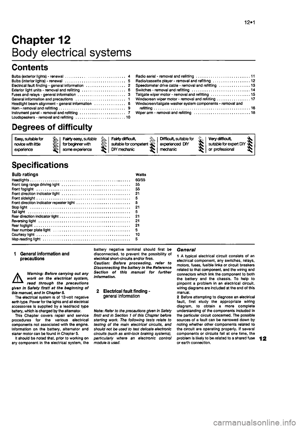
10*1
Chapter 12
Body electrical systems
Contents
Bulbs (exterior lights) - renewal 4 Bulbs (interior lights) - renewal 5 Electrical fault finding - general information 2 Exterior light units - removal and refitting 6 Fuses and relays - general Information 3 General information and precautions 1 Headlight beam alignment • general Information 6 Horn • removal and refitting 9 Instrument panel - removal and refitting 7 Loudspeakers - removal and refitting 10
Degrees of difficulty
Radio aerial - removal and refitting 11 Radio/cassette player • removal and refitting 12 Speedometer drive cable - removal and refitting 13 Switches - removal end refitting 14 Tailgate wiper motor - removal and refitting 15 Windscreen wiper motor - removal and refitting 17 Windscreen/tailgate washer system components • removal and refitting 16 Wiper arm • removal and refitting 18
Easy,
statable for ^
novice with liffle
|| experience ^
Fairly
easy,
suitable for beginner with ^ some experience ^
Fabtycffficiit,
suitable
for competent ^
DIY
mechanic ^
Difficult, suitable for
^ experienced DIY JR mechanic
Very difficult,
A,
suitable
for
expert DIY
Sj or professional ^
Specifications
Bulb ratings Watts Headlights 60/55 Front long range driving light 55 Front fogllght 55 Front direction Indicator light 21 Front sidelight 5 Front direction indicator repeater light 5 Stop light 21 Tall light 5 Rear direction indicator light 21 Reversing light 21 near fogllght 21 Hear number plate light 5 Courtesy light 10 Map reading light 5
1 Genera! information and precautions
A
Warning: fie/Ore carrying out any work on the electrical system, read through the precautions given in Safety first! at the beginning of this manual, and in Chapter 8. The electrical system is of 12-volt negative earth type. Power for the lights and all electrical accessories is supplied by a lead/acid type battery, which is charged by the alternator. This Chapter covers repair and service procedures for the various electrical components not associated with the engine. Information on the battery, alternator and starter motor can be found in Chapter 5. It should be noted that, prior to working on any component In the electrical system, the
battery negative terminal should first be disconnected, to prevent the possibility of electrical short-circuits and/or fires. Caution: Before proceeding, refer to Disconnecting the battery In the Reference Section of this manual for further information.
2 Electrical fault finding-general information
Note: Refer to the precautions given In Safety first! and in Section 1 of this Chapter before starting work. The following tests relate to testing ot the main electrical circuits, and should not be used to test delicate electronic circuits (such as antHock braking systems), particularly where an electronic con fro/ module is used.
General 1 A typical electrical circuit consists of an electrical component, any switches, relays, motors, fuses, fusible links or circuit breakers related to that component, and the wiring and connectors which link the component to both the battery and the chassis. To help to pinpoint a problem in an electrical circuit, wiring diagrams are Included at the end of this manual. 2 Before attempting to diagnose an electrical fault, first study the appropriate wiring diagram, to obtain a more complete understanding of the components included In the particular circuit concerned. The possible sources of a fault can be narrowed down by noting whether other components related to the circuit are operating properly. If several components or circuits fait at one time, the problem Is likely to be related to a shared fuse or earth connection.
Page 215 of 225
12*2 Body electrical systems
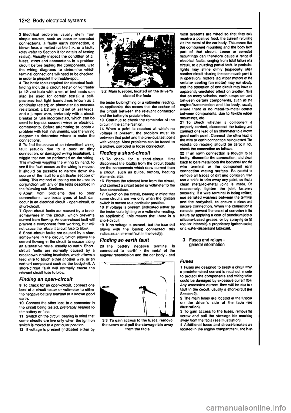
3 Electrical problems usually stem from simple causes, such as loose or corroded connections, a faulty earth connection, a blown fuse, a melted lusible link, or a fautty relay {refer to Section 3 for details of testing relays). Visually inspect the condition of all (uses, wires and connections in a problem circuit before testing the components. Use the wiring diagrams lo determine which terminal connections will need to be checked, in order to pinpoint the trouble-spot. 4 The basic tools required for electrical fault-finding include a circuit tester or voltmeter (a 12-volt bulb with a set of lest leads can also be used for certain tests}; a self-powered test light (sometimes known as a continuity tester); an ohmmeter (to measure resistance): a battery and set of tesi leads: and a lumper wire, preferably with u circuit breaker or fuse incorporated, which can be used to bypass susoect wires or electrical components. Before attempting to locate a problem with tost instruments, use the wiring diagram to determine where to make the connections. 5 To find the source of an intermittent wiring fault (usually due to a poor or dirty connection, or damaged wiring Insulation), a wiggle test can be performed on the wiring. This involves wiggling the wiring by hand, to see if tha fault occurs as the wiring Is moved. It should be possible to narrow down the source of the fault to a particular section of wiring. This method of testing can be used in conjunction with any of the tests descnbed in the following sub-Sections. 6 Apart from problems due to poor connections, two basic types of fault can occur in an electrical circuit - open-circuit, or short-circuit. 7 Open-circuit faults are caused by a break somewhere in the circuit, which prevents current from flowing. An open-circuit fault will prevent a component from working, but will not cause the relevant circuit fuse to blow 8 Short-circuit faults are caused by a shod somewhere in the circuit, which allows Die current flowing In the circuit to escape along an alternative route, usually to earth. Short-circuit faults are normally caused by a breakdown in wiring insulation, which allows a feed wire to touch either another wire, or an earthed component such as the bodysheli. A short-circuit fault will normally cause the relevant circuit fuse to blow.
Finding an open-circuit 9 To check for an opon-circuit, connect one lead of a circuit tester or voltmoter to either the negative battery terminal or a known good earth. 10 Connect the other lead to a connector in the circuit being tested, preferably nearest to the batter/ or luse. 11 Switch on the circuit, bearing In mind that some circuits are live only when tho ignition switch is moved to a particular position. 12 If voltage is present (Indicated either by
3.2 Main fuse box, located on the driver's side of the facie the toster bulb lighting or a voltmeter reading, as applicable), this means that tho section of Ihe circuit between the relevant connector and the battery is problem-free. 13 Continue to check the remainder ot the circuit in the same fashion. 14 When a point is reached at which no voltage Is present, the problem must lie between that point and the previous test point with voltage. Most problems can be traced to a broken, corroded or loose connection.
Finding a short-circuit 15 To check for a short-circuit, first disconnect the load(s) from the circuit (loads are the components which draw current from a circuit, such as bulbs, motors, heating elements, etc). 16 Remove the relevant luse Irom the circuit, and connect a circuit tester or voltmeter to the luse connections. 17 Switch on the circuit, beanng in mind that some circuits are live only when the ignition switch is moved to a particular position. 18 If voltage is present (indicated either by the tester bulb lighting or a voltmeter reading, as applicable), this means that there Is a short-circuit. 19 If no voltage is present, but the fuse still blows with the load(s) connected, this indicates an internal fault in the load(s).
Finding an earth fault 20 The battery negative terminal Is connected to 'earth' - the metal of the engine/transmission and the car body - and
I
IK
J 3.3 To gain access to the fuses, remove the screw and pull the stowage bin away from the facia
most systems are wired so that they only receive a positive feed, the current returning via the metal of Ihe car body. This means that the component mounting and the body form part of that circuit. Loose or corroded mountings can therefore cause a range of electrical faults, ranging from total failure ot a circuit, to a puzzling partial fault. In particular, lights may shine dimly (especially when another circuit sharing the same earth port In operation), motors (eg wiper motors v Ihe radiator cooling fan motor) may run slowly, and Ihe operation of one circuit may have an apparently-unrelated effect on another. Ncie that on many vehicles, earth straps axe uses between certain components, such as the engine/transmission and the body, usually whore there is no metal-to-metal contact between components, due to flexible rubber mountings, etc. 21 To check whether a component $ properly earthed, disconnect Ihe battery, and connect one lead of an ohmmeter to a kwwi good earth point. Connect the other lead to the wire or earth connection being tested. Tha resistance reading should be zero; if not. check the connection as follows. 22 If an earth connection Is thought to be faulty, dismantle the connection, and clean pack to bare metal both the bodysheli and ite wire terminal or the component earth connection mating surface. Be careful to remove all traces of dirt and corrosion, then use a knife to trim away any palm, so thai a clean metal-to-metal joint Is mads. On reassemoly, tighten the joint fasteners securely: if a wire terminal Is being refitted, use serrated washers between tho terminal and the bodysheli. to ensure a clean and secure connection. When the connection is remade, prevent the onset ot corrosion in the future by applying a coat of petroleum idly
or
stlicone-based grease, or by spraying on (a: regular intervals} a proprietary ignition eoater, or a water-aispersant lubneant.
3 Fuses and relays -general information
Fuses 1 Fuses are designod to break a circuit when a predetermined current is reached, in order to protect the components and wiring wttioh could be damaged by excessive current How. Any excessive current flow will be due to a fault in the circuit, usually a short-circuit (see Section 2). 2 The main fuses are located in the fusefcox on the driver's side of the facia (see illustration). 3 To gain access to the fuses, remove tne screw and pull the stowage bin moulding away from the facia (see illustration). 4 Additional fuses and circuit-breakers are located In the engine compartment, and in an
Page 223 of 225
12*10 Body electrical systems
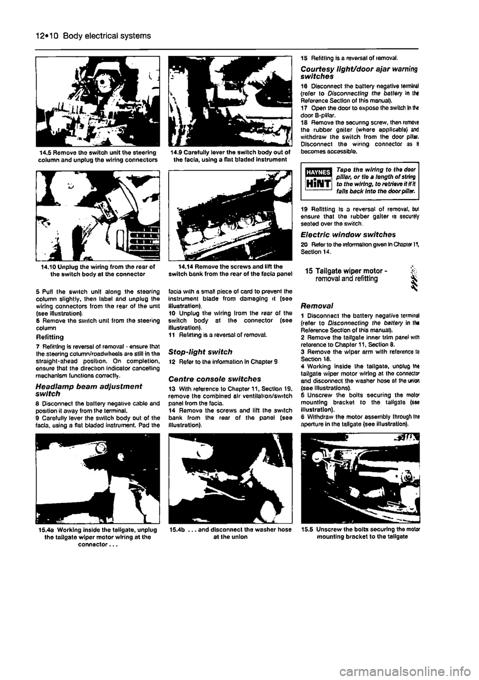
14.5 Remove the switch unit the steering column and unplug the wiring connectors 14.9 Carefully lever the switch body out of the facia, using a flat btaded instrument
14.10 Unplug the wiring from tho rear of the switch body at the connector
5 Pull the switch unit along ihe steering column slightly, then label and unplug the wiring connectors from the rear of the unit (sec Illustration). 6 Remove the switch unit from the steering column Refitting 7 Refitting is reversal of removal • ensure that the steering column/roadwheels are still in the straight-ahead position. On completion, ensure that the direction indicator cancelling mechanism lunations correctly.
Headlamp beam adjustment switch 8 Disconnect the battery negative cable and position il away from the terminal. 9 Carefully lever the switch body out of the facia, using a flat bladed instrument. Pad the
15 Refitting is a reversal of removal. Courtesy light/door ajar warning switches 16 Disconnect the battery negative terminal (refer to Disconnecting the battery in thf Reference Section of this manual). 17 Open the door to expose the switch
in
the door 8-plHar. 18 Remove the secunng screw, then remove the rubber gaiter (where applicable) ant) withdraw the switch from the door pillar. Disconnect the wiring connector as tl becomes accessible.
Tape the wiring to the
door
i m | pillar, or tie a length of
string
HlNTi to the wiring, to retrieve itttit falls back Into the door pillar.
14.14 Remove the screws and lift the switch bank from the rear of the facia panel
facia with a small piece of card to prevent the Instrument blade from damaging it (see illustration). 10 Unplug the wiring Irom Ihe rear of the switch body at Ihe connector (see illustration). 11 Refitting is a reversal of removal
Stop-light switch 12 Refer to the information in Chapter 9
Centre console switches 13 With reference to Chapter 11, Section 19, remove the combined air ventilation/switch panel from the facia. 14 Remove the screws and lift Ihe switch bank from Ihe rear of the panel (see illustration),
19 Refitting Is a reversal of removal, but ensure that the rubber gaiter is securely seated over the switch.
Electric window switches 20 Refer to the information given
In
Chapter It, Section 14.
15 Tailgate wiper motor - & removal and refitting ^
Removal 1 Disconnect the battery negative terminal (refer to Disconnecting the battery in the Reference Section of this manual), 2 Remove the tailgate inner trim panel with reference to Chapter 11, Section 8. 3 Remove the wiper arm with reference to Section 18. 4 Working inside the tailgate, unplug tlx tailgate wiper motor wiring at Ihe connector and disconnect the washer hose at
1he
union (see illustrations). 6 Unscrew the bolts securing the motor mounting bracket to the tailgate (see illustration). 6 Withdraw the motor assembly through tte aperture in the tailgate (see illustration).
15.4a Working inside the tellgate, unplug tho tailgate wiper motor wiring at the connector...
. and disconnect tho washer hose at the union 15.5 Unscrew the bolts securing the motor mounting bracket to the tailgate
Page 224 of 225
Body electrical systems 12*11
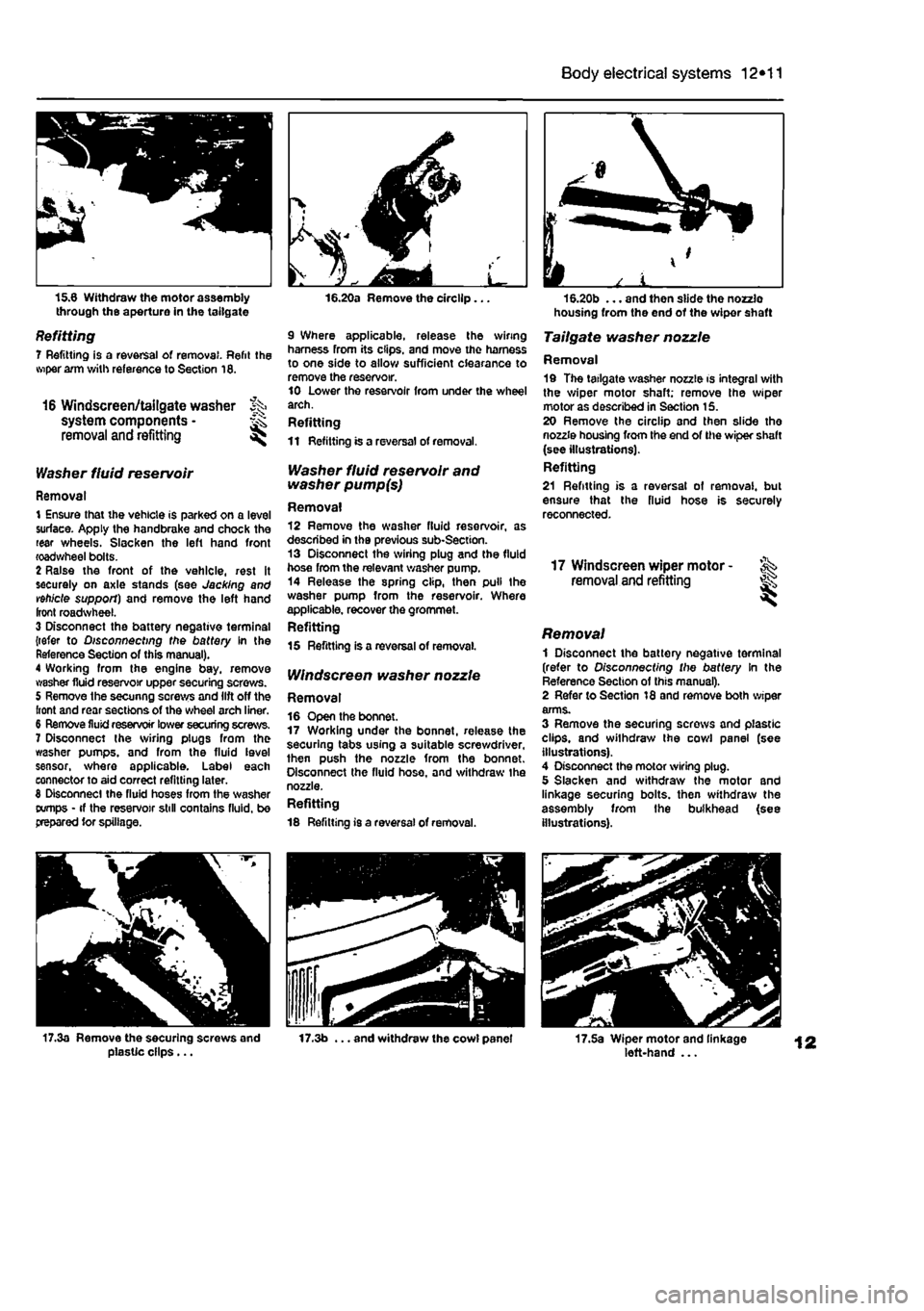
15.6 Withdraw the motor assembly through the aperture in the tailgate
Refitting 7 Refitting is a reversal of removal. Refit the wiper arm with reference to Section 16.
16 Windscreen/tailgate washer % system components • ^ removal and refitting ^
Washer fluid reservoir
Removal 1 Ensure that the vehicle is parked on a level surface. Apply the handbrake and chock the rear wheels. Slacken the left hand front roadwheel bolts. 2 Raise the front of the vehicle, rest it securely on axle stands (see Jacking and vehicle support) and remove the left hand front roadwheel. 3 Disconnect the battery negative terminal {refer to Disconnecting the battery In the Reference Section of this manual). 4 Working from the engine bay, remove washer fluid reservoir upper securing screws. 5 Remove the secunng screws and lift off the front and rear sections of the wheel arch liner. 6 Remove fluid reservoir lower securing screws. 7 Disconnect the sviring plugs from the washer pumps, and from the fluid level sensor, where applicable. Label each connector to aid correct refitting later. 8 Disconnect the fluid hoses from the washer tx/mps • if the reservoir still contains fluid, be prepared tor spillage.
16.20a Remove the circllp...
9 Where applicable, release the wiring harness from its clips, and move the harness to one side to allow sufficient clearance to remove the reservoir. 10 Lower the reservoir from under the wheel arch. Refitting 11 Refitting is a reversal of removal.
Washer fluid reservoir and washer pump(s)
Removal 12 Remove the washer fluid reservoir, as described in the previous sub-Section. 13 Disconnect the wiring plug and the fluid hose from the relevant washer pump. 14 Release the spring clip, then pull the washer pump from the reservoir. Where applicable, recover the grommet. Refitting 15 Refitting is a reversal of removal.
IV/nctecreen washer nozzle
Removal 16 Open the bonnet. 17 Working under the bonnet, release the securing tabs using a suitable screwdriver, then push the nozzle from the bonnet. Disconnect the fluid hose, and withdraw the nozzle. Refitting 18 Refitting is a reversal of removal.
housing from the end of the wiper shaft
Tailgate washer nozzle
Removal 19 The tailgate washer nozzle is integral with the wiper motor shaft; remove the wiper motor as described in Section 15. 20 Remove the circllp and then slide the nozzle housing from the end of the wiper shaft (see illustrations). Refitting 21 Refitting is a reversal of removal, but ensure that the fluid hose is securely reconnected.
17 Windscreen wiper motor -removal and refitting ^
Removal 1 Disconnect the battery negative terminal (refer to Disconnecting the battery In the Reference Section of this manual). 2 Refer to Section 18 and remove both wiper arms. 3 Remove the securing screws and plastic clips, and withdraw the cowl panel (see illustrations). 4 Disconnect the motor wiring plug. 5 Slacken and withdraw the motor and linkage securing bolts, then withdraw the assembly from the bulkhead (see illustrations).
17.3a Remove the securing screws and plasUc clips... 17.3b ... and withdraw the cowl panel 17.5a Wiper motor and linkage left-hand ...
Page 225 of 225
12*12 Body electrical systems
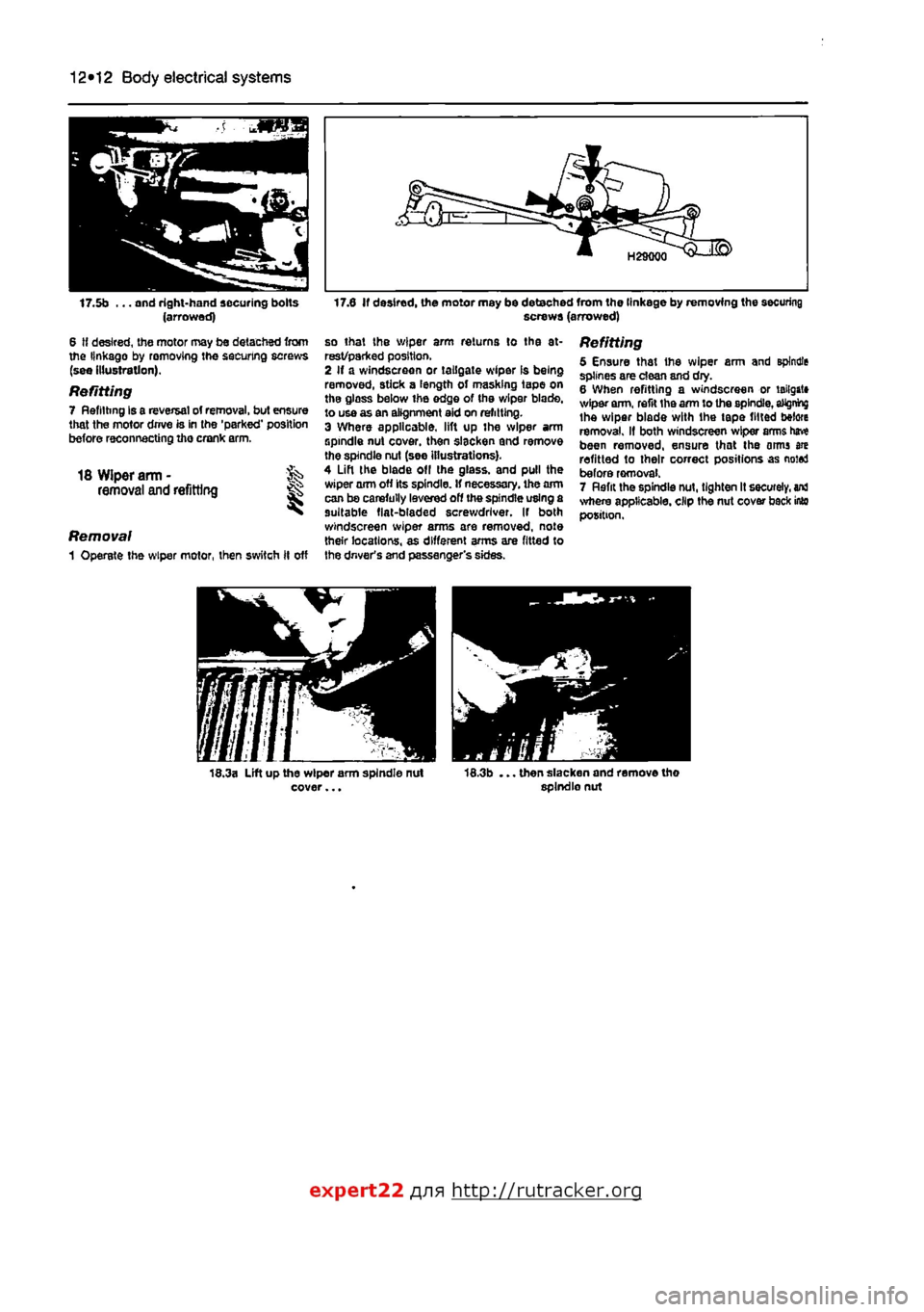
17.0 If desired, the motor may be detached from the linkage by removing the securing screws (arrowed) 17.5b ... and right-hand securing bolts (arrowed)
6 If desired, the motor may be detached from the linkage by removing the securing screws (see illustration).
Refitting 7 Refitting Is a reversal of removal, but ensure that the motor drrve is in the 'parked' position before reconnecting ihe crank arm.
18 Wiper arm - fe removal and refitting
Removal 1 Operate the wiper motor, then switch ft off
so that the wiper arm returns to tha at-rest/parked position, 2 If a windscreen or tailgate wiper Is being removed, stick a length of masking tape on tha glass below ihe edge of tha wiper blade, to use as an alignment aid on refitting. 3 Where applicable, lift up the wiper arm spindle nut cover, then slacken and remove the spindle nut (see illustrations). 4 Lift the blade of
I
the glass, and pull the wiper arm off its spindle. If necessary, the aim can be carefully lavered off the spindle using a suitable fiat-bladed screwdriver. If both windscreen wiper arms are removed, note their locations, as different arms are fitted to the driver's and passenger's sides.
Refitting 5 Ensure that the wiper arm and spindle splines are dean and dry. 6 When refitting a windscreen or tailgate wiper arm, refit tha arm to the spindle,
aMgnhg
the wiper blade with the tape fitted before removal. If both windscreen wiper arms have been removed, ensure that the arms are refitted to their correct positions as noted before removal. 7 Rflfit the spindle nut, tighten It securely,
ana
where applicable, clip the nut cover back into position.
expert22 fl/in http://rutracker.org