Crankshaft FIAT PUNTO 1998 176 / 1.G Repair Manual
[x] Cancel search | Manufacturer: FIAT, Model Year: 1998, Model line: PUNTO, Model: FIAT PUNTO 1998 176 / 1.GPages: 225, PDF Size: 18.54 MB
Page 161 of 225
6*4 Clutch
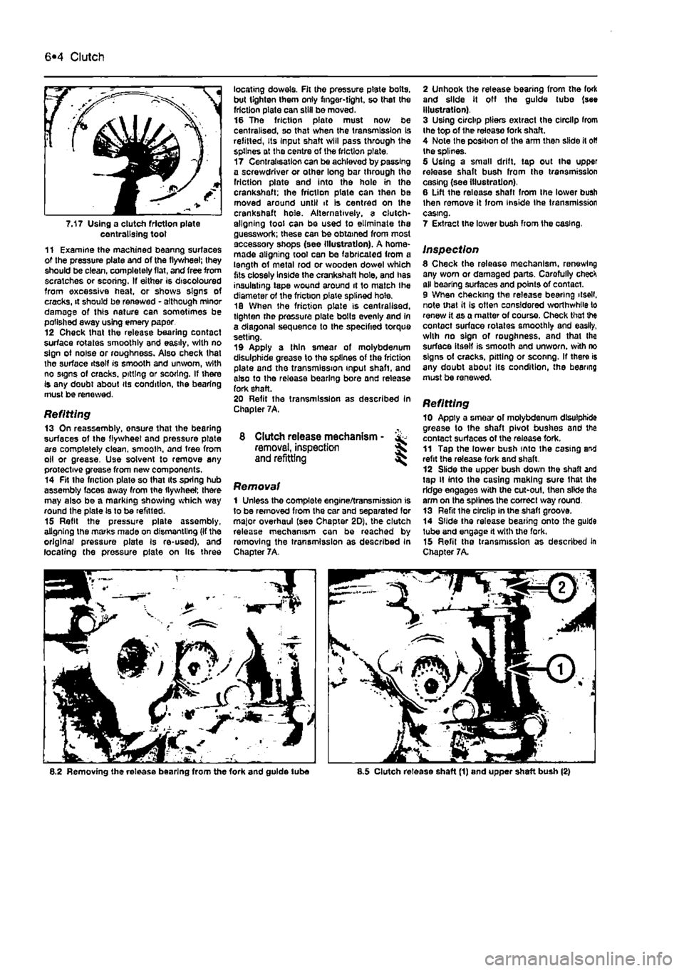
7.17 Using a clutch friction plate centralising toot 11 Examine the machined beanng surfaces of the pressure plate and of the flywheel; they should be clean, completely flat, and free from scratches or scoring. If either is discoloured from excessive heat, or shows signs of cracks, it should be renewed - although minor damage of this nature can sometimes be polished away using emery paper 12 Check that the release bearing contact surface rotates smoothly and easily, with no sign of noise or roughness. Also check that the surface itself is smooth and unworn, with no signs of cracks, pitting or scoring. If there Is any doubt about its condition, the bearing must be renewed.
Refitting 13 On reassembly, onsure that the bearing surfaces of the flywheel and pressure plate are completely clean, smoolh. and tree from oil or grease. Use solvent to remove any protective grease from new components. 14 Fit the friction plate so that its spring hub assembly faces away from the flywheel; there may also be a marking showing which way round the plate Is to be refitted. 15 Refit the pressure plate assembly, aligning the marks made on dismantling (If the original pressure plate Is re-used), and locating the pressure plate on Its three
locating dowels. Fit the pressure plate bolts, but tighten them only finger-tight, so thai the friction plate can skill be moved. 16 The friction plate must now be centralised, so that when the transmission Is refitted, Its Input shaft will pass through the splines at the centre of the friction plate. 17 Centralisation can be achieved by passing a screwdriver or other long bar through the friction plate and into the holo in the crankshaft; the friction plate can then be moved around until it is centred on the crankshaft hole. Alternatively, a clutch-aligning tool can be used to eliminate the guesswork; these can be obtained from most accessory shops (see illustration). A home-made aligning tool can be fabricated from a length of metal rod or wooden dowel which fits closely Inside the crankshaft hole, and has insulating tape wound around it to match Ihe diameter of the friction plate splined hole. 18 When the friction plate is centralised, tighten tho pressure plate bolts evenly and In a diagonal sequence to the specified torque setting. 19 Apply a Ihin smear of molybdenum dlsulphide grease to the splines of the friction plate and the transmission input shaft, and also to the release bearing bore and release fork shaft. 20 Refit the transmission as described In Chapter 7A.
8 Clutch release mechanism - & removal, inspection J and refitting ^
Removal 1 Unless the complete engine/transmission is to be removed from the car and separated lor major overhaul (see Chapter 2D), the clutch release mechanism can be reached by removing the transmission as described In Chapter 7A.
2 Unhook the release bearing from the fork and slide it off Ihe guide tubo (see illustration). 3 Using circlip pliers extract the circllp Irom the top of the release fork shaft. 4 Note the position of the arm then slide it
oW
the splines. 5 Using a small drift, tap out the upper release shaft bush from the transmission casing (see illustration). 6 Lift the release shaft from Ihe lower bush then remove it Irom inside Ihe transmission casing.
7 Extract the lower bush from 1he casing.
inspection 8 Check (he release mechanism, renewing any worn or damaged parts. Carofully checH all bearing surfaces and points of contact. 9 When checking the release bearing ilsell. note that it Is often considered worthwhile to renew it as a matter of course. Check thai the contact surface rotates smoothly and easily, with no sign of roughness, and that Ihe surface itself is smooth and unworn, with no signs of cracks, pitting or sconng. If there is any doubt about Its condition, the bearing must be renewed, Refitting 10 Apply a smear of molybdenum dlsulphide grease to the shaft pivot bushes and the contact surfaces of the release fork. 11 Tap the lower bush into the casing and refit the release fork and shaft. 12 Slide the upper bush down the shaft and tap it into the casing making sure lhat the ridge engages with the cut-out. then slide the arm on the splines the correct way round. 13 Refit the circlip in the shaft groove. 14 Slide the release bearing onto the guide tube and engage it with the fork. 15 Refil the transmission as described in Chapter 7A.
8.2 Removing the release bearing from the fork and guide lube 8.5 Clutch release shaft (1) and upper shaft bush (2)
Page 162 of 225
7A»1
Chapter 7 Part A:
Manual transmission
Contents
Gearchange lever and linkage - removal and refitting 2 General information 1 Manual transmission oil level check See Chapter 1A or 18 Manual transmission oil renewal See Chapter 1A or 1B
Manual transmission overhaul • general information 4 Manual transmission • removal and refitting 3 Reversing light switch • testing, removal and refitting 5
Degrees of difficulty
Easy, suitable
for Faiity
easy,
suitable FaMycffficult, ^ Difficult,
sutable fa-
Verycfifficutt, ^
novice with
little
1
for beginner with suitable
for
competent experienced DIY * * < siitable
for
expert
DIY
jR or professional ^ experience 1
some
experience DIYmechanic ^ mechanic * * < siitable
for
expert
DIY
jR or professional ^
Specifications
General Type
Designation: 1108 cc petrol engine 1242 cc petrol engine Non-turbo diesel engine Turbo diesel engine
Torque wrench settings Gear lever support nut Gear lever to mounting Reverse gear inhibitor cable to transmission Reversing light switch Selector rod-to-gear lever nut Speedometer drive Transmission-to-engine bolt/nut
Transverse mounted, front wheel drive layout with integral transaxle differential/final drive. 5 or 6 forward speeds, 1 reverse speed
C.S14.5.10 (5-speed) or C.514.6.10 (6-speed) C.514.5.1Q/13 (5-speed) C.514.5.13 (5-speed) C.510.5.17 (5-speed)
Nm Ibftl 6 4 49 36 30 22 40 30 17 13 12 9 es 63
1 Genera) Information
The transmission is contained In a cast-aluminium alloy casing bolted to the engine's left-hand end, and consists of the gearbox end final drive differential, Drive Is transmitted from the crankshaft via the clutch to the Input shaft, which has a spiined extension to accept the clutch friction
plate, and rotates in roller bearings at its right-hand end and ball bearings at its left-hand end (on 6-speed versions the left-hand extension rotates In a roller bearing). From the input shaft, drive is transmitted to tho output shaft, which rotates In roller bearings at Its right-hand end. and ball bearings at its left* hand end (on 6-speed versions the left-hand extension rotates in ball bearings). From the output shaft, the drive is transmitted to the differential crownwheel, which rotates with the differential case and gears in taper roller bearings, thus driving the sun gears and
driveshafts. The rotation of the differential gears on their shaft allows the inner roadwheel to rotate at a slower speed than the outer roadwheel when the car is cornering. The Input and output shaftB are arranged side by side, parallel to the crankshaft and driveshafts, so that their gear pinion teeth are In constant mesh. In the neutral position, the relevant input shaft and output shaft gear pinions rotate freely, so that drive cannot be transmitted to the output shaft and crownwheel.
Page 168 of 225
Automatic transmission 7B*3
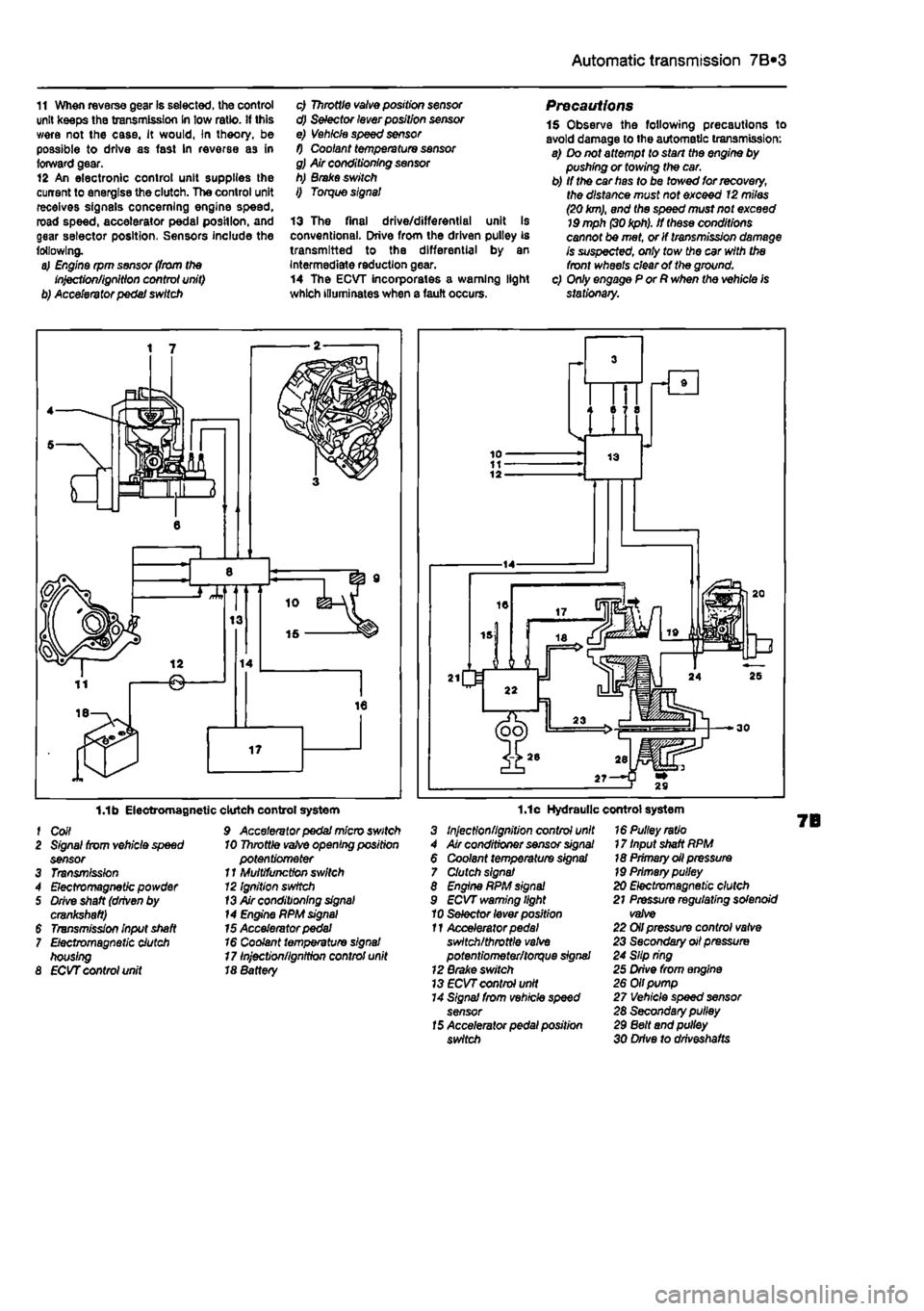
11 When reverse gear Is selected, the control unit keeps the transmission In tow ratio, if this were not the case, it would, In theory, be possible to drive as fast In reverse as in forward gear. 12 An electronic control unit supplies the current to energise the clutch. The control unit receives signals concerning engine speed, road speed, accelerator pedal position, and gear selector position, Sensors include the following. a) Engine rpm sensor (from the Injection/ignition control unit) b) Accelerator pedal switch
c) Throttle valve position sensor d) Selector lever position sensor e) Vehicle speed sensor f) Coolant temperature sensor g) Air conditioning sensor h) Brake switch I) Torque signal
13 The final drive/differential unit Is conventional. Drive from the driven pulley is transmitted to the differential by an Intermediate reduction gear. 14 The ECVT incorporates a warning light which illuminates when a fault occurs.
Precautions 1$ Observe the following precautions to avoid damage to the automatic transmission: a) Do not attempt to start the engine by pushing or towing the car. b) If the car has to be towed for recovery, the distance must not exceed 12 miles (20
km),
and the speed must not exceed
19
mph
(30 kph).
If these conditions cannot be met, or If transmission damage is suspected, only tow the car with the front wheels clear of the ground. c) Only engage P or R when the vehicle is stationary.
1.1b Electromagnetic f Coil 2 Signal from vehicle speed sensor 3 Transmission 4 Electromagnetic powder 5 Drive shaft (driven by crankshaft) $ Transmission input shaft 7 Electromagnetic clutch housing 8 ECVT control unit
clutch control system 9 Accelerator pedal micro switch 10 Throttle
vafve
opening position potentiometer 11 Multifunction switch 12 Ignition switch
13
Air conditioning
signal
14 Engine PPM
signal
15 Accelerator pedal 16 Coolant temperature signal 17 Injection/ignition control unit 18 8attery
1.1c Hydraulic control system 3 Injection/ignition control unit 4 Air conditioner sensor
signal
6 Coolant temperature signal 7 Clutch signal 8 Engine RPM
signal
9 ECVT warning light 10 Selector lever position 11 Accelerator
pedal
switch/throttle
valve
potentiometer/torque signal 12 Brake switch 13
ECVT
control unit 14 Signal from vehicle speed sensor
15
Accelerator pedal position switch
16 Pulley ratio 17 Input shaft RPM 18 Primary oil pressure
19
Primary pulley 20 Electromagnetic clutch 21 Pressure regulating solenoid valve 22 Oil pressure control valve 23 Secondary oil pressure 24 Slip ring 25 Drive from engine 26 Oil pump 27 Vehicle speed sensor 28 Secondary pulley 29 Belt and pulley 30 Drive to drlveshafts
Page 169 of 225
7B*4 Automatic transmission
2 Automatic transmission - ^ removal and refitting St
Removal 1 Select a solid, level surface to park the vehicle upon. Give yourself enough space to move around it easily. Apply the handbrake then jack up the front of the vehicle and support on axle stands (see Jacking and vehicle support). Remove both front wheels, 2 Remove the battery and mounting tray as described In Chapter 5A. 3 Remove the air cleaner and air inlet duct as described In Chapter 4A. 4 Disconnect the kickdown cable at the sector on the throttle housing and detach It from the mounting on the camshaft cover. Also release the cable from the support on the left-hand end of the cylinder head. 5 Disconnect the wiring connectors on the transmission. 6 Disconnect the fluid inlet and outlet Unas from the heat exchanger on top of the transmission. 7 Pull the fluid level dipstick from Its tube on the front of the transmission and tape over the top of the tube to prevent dirt entry. 8 Unscrew and remove the retaining pin and disconnect the speed selector cable from the top of the transmission. 9 Unscrew the upper bolt securing the starter motor to the transmission. 10 Unscrew the upper bolts securing the transmission to the engine. 11 Support the weight of the engine using a hoist attached to the engine lifting eyes, or alternatively UBO a trolley jack and block of wood beneath the engine, 12 Remove the screws and remove the front wheel arch liner from under the left-hand wheel arch. 13 Unscrew the nut securing the earth cablo to the transmission. 14 Using a punch drive out the roll pins securing both driveshafts to the final drive output shafts. 15 Unscrew and remove the bolts securing the left-hand swivel hub assembly to the front suspension strut, then separate the components and support the swivel hub on an axle stand. 16 Move the swivel hub assembly outwards and slide the inner end of the driveshaft from the splines on the transmission output shaft. Support the shaft away from the transmission to prevent damage to the gaiters. 17 Unscrew the lambdafoxygen sensor from the exhaust downpipe and position it In a safe place to prevent damage. 18 Unscrew ihe nuts securing the downpipe to Ihe exhaust manifold, then lower It and suppon on an axle stand. Recover the gasket. 19 Unscrew the knurled nut and disconnect the speedometer cable from the top of the final drive housing.
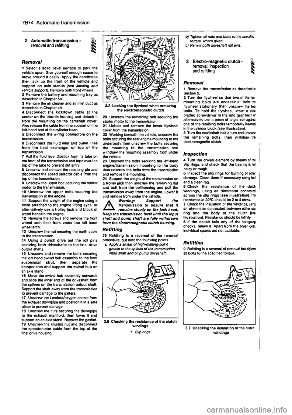
3-2 Locking the flywheel when removing the electromagnetic clutch 20 Unscrew the remaining bolt securing the staner motor to the transmission 21 Unbolt and remove Ihe lower flywheel cover from the transmission. 22 Working beneath the vehicle, unscrew the bolts securing the rear engine mounting to the underbody then unscrew the bolts securing the mounting lo the transmission and withdraw the mounting assembly from under the vehicle. 23 Unscrew the bolts securing the left-hand engine/transmission mounting to the body thon unscrew the bolts from the transmission and remove the mounting. 24 Support the weight of the transmission on a trolley jack then unscrew the remaining nut and bolt from the bellhouslng and pull the transmission away from the engine. Lower it and remove from under the vehicle.
A
Warning: Support the transmission to ensure that It remains steady on the Jack head. Keep the transmission level until the Input shaft and pump shaft are fully withdrawn from the electromagnetic clutch housing.
Refitting 25 Refitting is a reversal of the removal procedure, but note the following points. a} Apply a smear of high-melting-point grease to the splines of the transmission input shaft and oil pump driveshaft.
3.6 Checking the resistance of the clutch windings 1 Slip rings
0) Tighten all nuts and bolts to the
specified
torque, where given, c) Renew both driveshaft roll pins.
3 Electro-magnetic clutch • & removal, inspection 5. and refitting ^
Removal 1 Remove Ihe transmission as described n Section 2. 2 Turn the flywheel so that two of the lour mounting bolts are accessible, Hold tha flywheel stationary then unscrew Ihe tvrt bolts. To hold the flywheel, Insert a wida bladed screwdriver In the ring gear teeth or alternatively use a piece of angle iron against one of the retaining bolts temporarily Inserted in the cylinder block (see illustration). 3 Turn the crankshaft half a turn and unscrew the remaining bolts, then withdraw the electromagnetic clutch.
Inspection 4 Turn the driven element by means of tha slip rings, and check that the bearing is not noisy or rough. 5 Inspect the slip rings for burning or other damage. Clean them if necessary using fid and a clean rag. 6 Check the resistance of the clutch windings, using an ohmmetor connected across the slip rings (see Illustration). The resistance at 20*0 should be 2 to 4 ohms. 7 Check the Insulation of the windings, using an ohmmeter connected between either sip ring and the body of the clutch (see illustration). Resistance should be Infinity. 8 If the clutch fails any of the foregoing checks, renew it. Apart from the brush gear, Individual spares are not available.
Refitting 9 Refitting is a reversal of removal but tighten all bolts to the specified torque.
windings
Page 190 of 225
Suspension and steering 10*2
Torque wrench settings (continued) Nm ibt ft Rasr suspension Damper lower securing bolt 95 70 Damper upper securing bolt 60 44 Handbrake cable support bracket-to-trailing arm screws 15 11 Hub nut 280 207 Trailing arm securing bolt 150 111 Steering Ignition switch/steering column lock securing bolts 4 3 Steering column mounting bolts 55 41 Steering gear mounting bolts 70 52 Steering wheel nut' 50 37 Subframe-to-body bolts 110 81 Track-rod end to hub carrier 40 30 Unlversaijointclampbolts 20 15 Roadwheels Roadwheel bolts 85 63 * Use a new nut
1 General information
Front suspension The front suspension is independent, comprising transverse lower wishbones, coil spring-over-damper strut units and an anti-roll bar. The hub carriors are bolted to the base of the stmt units and are linked to the lower arms by means ot balliotnts. The entire front suspension assembly is mounted on a subframe, which is In turn botted to the vehicle body.
Rear suspension The rear suspension incorporates a torsion beam axle, trailing arms, coil springs and separate telescopic dampers. In addition, a rear anil-roll bar is fitted to certain models. The components form a discrete sub-assembly which can be unboiled from the underside of the vehicle separately or as a complete unit.
Steering The two-piece steering shaft runs in a tubular column assembly, which is bolted to a bracket mounted on the vehicles bulkhead. The shaft Is articulated at its lower end by means of a universal Joint, which is clamped to the steering shaft and the steering gear pinion by moans of clamp bolts. The steering gear is mounted on the engine compartment bulkhead, and is connected to the steering arms projecting rearwards from Ihe hub carriers. The track-rods are fitted with balljoints at their inner and outer ends, to allow for suspension movement, and are threaded to facilitate ad|ustment. Hydrauiically-assisted power steering ts fittod to some models. The hydraulic system is powered by a belt-driven servo pump, which is driven from the crankshaft pulley.
Certain models are fitted with an airbag system. Sensors built into the vehicle body are triggered in the event of a front end collision and prompt an Electronic Control Unll (ECU) to activate the airbag, mounted In the centre of the steering wheel and the facia. This reduces the risk of the front seat occupants striking the steering wheel, windscreen or facia during an accident.
A
Warning: For safety reasons, owners are strongty advised to entrust to an authorised Flat dealer any work which involves disturbing the airbag system components. The airbag inflation devices contain explosive material and legislation exists to control their handling and storage, in addition, specialised test equipment Is needed to check that the airbag system Is fully operational following reassembly.
2 Front hub bearings -renewal *
Note: A balljoint separator tool, and a press or suitable alternative tools (see text) will be required for this operation. The bearing will be destroyed during the removal procedure.
Removal 1 Chock the rear wheels, apply the handbrake, then jack up the front of the vehicle and support on axle stands (see Jacking and vehicle support). Remove the appropriate roadwheel. 2 Remove the brake disc and caliper, with reference to Chapter 9. Note that the caliper body can remain bolted to its bracket: there is no need lo disconnect the brake fluid hose from the caliper. 3 With reference to Chapter 8. slacken and remove the driveshaft hub nut. 4 On models with ABS, unbolt the ABS wheel sensor, and remove the screw securing the
ABS sensor wiring to the hub carrier. Suspend the sensor away from the working ares, to avoid the possibility of damage. 5 With reference to Section 17, separate
th»
track-rod end from the hub carrier, using
a
suitable balljoint splitter. 6 Remove the two nuts from tho botts securing Ihe hub carrier to the base of th» suspension strut (refer to Section
3).
Withdrew the bolts and separate the top of hub earrtt from the strut. 7 Disconnect the outboard end of Ito driveshaft from the hub, as described durirg the driveshaft removal and refitting procedm in Chapter 8. Note: There is no naod fo disconnect the Inboard end of the
drivestett
from the transmission. Caution: Do not allow the end of tin driveshaft to hang down under its
own
weight, as this places strain on the
CV
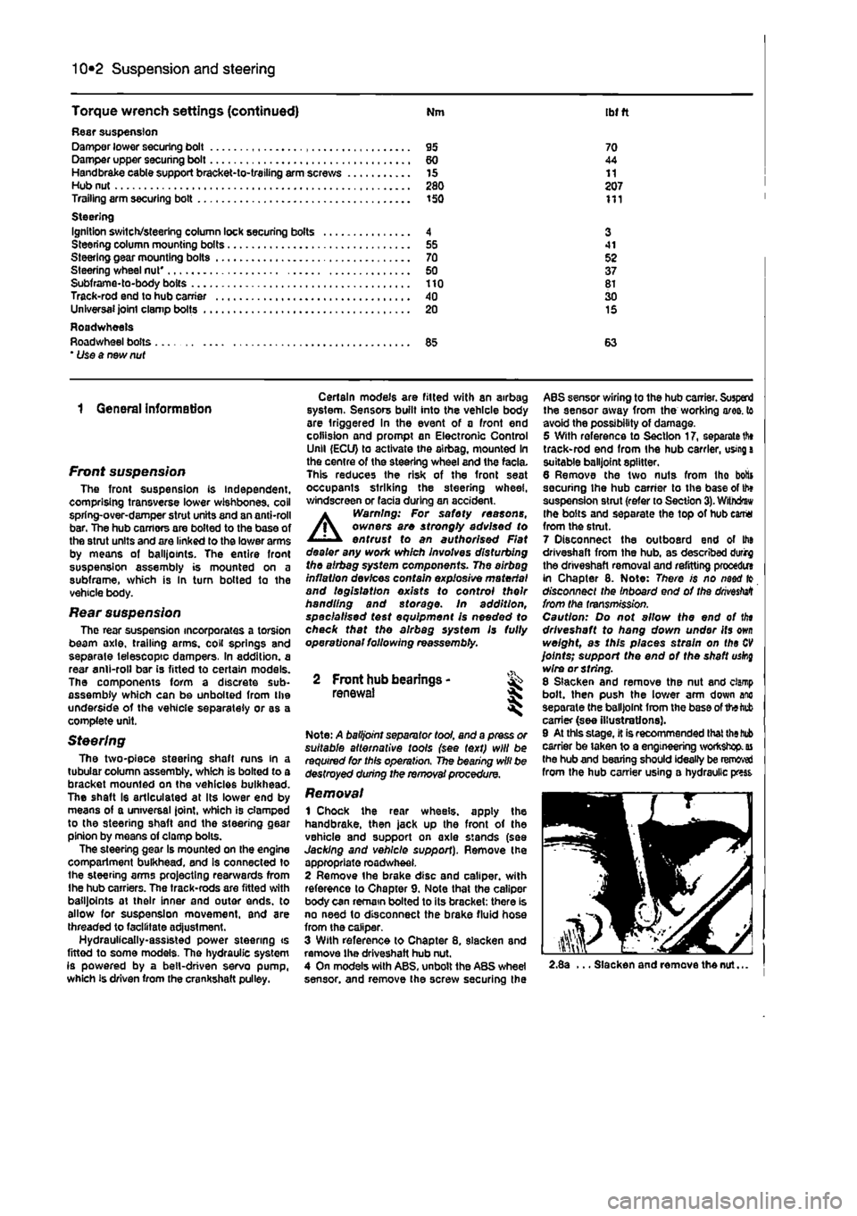
joints; support the end of the shaft uskg wire or string. 8 Slacken and remove the nut and clamp bolt, then push the lower arm down anc separate the balljoint from the base of the tab carrier (see illustrations). 9 At this stage, it is recommended that
the bub
carrier be taken to a engineering workshop,
as
the hub and bearing should ideally be removed from the hub carrier using a hydraulic press
2.8a ... Slacken and remove the nut...