Indicator FIAT PUNTO 1998 176 / 1.G Workshop Manual
[x] Cancel search | Manufacturer: FIAT, Model Year: 1998, Model line: PUNTO, Model: FIAT PUNTO 1998 176 / 1.GPages: 225, PDF Size: 18.54 MB
Page 10 of 225
Roadside repairs 0.9
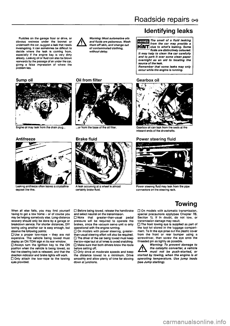
Puddles on the garage floor or drive, or obvious wetness under the bonnet or underneath the car, suggest a leak that needs Investigating. It can sometimes be difficult to decide where the leak is coming from, especially if the engine bay is very dirty already. Leaking oil or fluid can also be blown rearwards by the passage of air under the car, giving a false impression of where the problem lies.
A
Warning: Most automotive oils and fluids aro poisonous. Wash them off skin, and change out of contaminated clothing, without delay.
Identifying leaks
The smell of 0 fluid leaking from the car may provide a clue to what's leaking. Some fluids are distinctively coloured. It may help to clean the car carefully and to park It over some clean paper overnight as an aid to locating the source of the leak. Remember that some leaks may only occur while the engine is running.
Sump oil
Engine oil may leak from the drain plug...
Antifreeze
Leaking antifreeze often leaves a crystalline oeposit like this.
Oil from filter
A leak occurring at a wheel Is almost certainly brake fluid.
Gearbox oil
Gearbox oil can leak from the seals at the inboard ends of the drivoshafts.
Power steering fluid
Power steering fluid may leak from the pipe connectors on the steering rack.
When ail else falls, you may llnd yourself having to get a tow home - or of course you may be helping somebody else. Long-distance recovery should only be done by a garage or breakdown service. For shorter distances. OIY towing using another car is easy enough, but observe the following points: • Use a proper tow-rope - they are not expensive. The vehicle being towed must display an ON TOW sign in its rear window. • Always turn the Ignition key to the ON position when the vehicle is being towed, so that the steering lock is released, and that the direction indicator and brake lights will work. • Only attach the tow-rope to the towing eyes provided.
• Before being towed, release the handbrake and select neutral on the transmission. • Note that greater-then-usual pedal pressure will be required to operate the brakes, since the vacuum servo unit is only operational with the engine running. • On models with power steering, greater-than-usual steering effort will also be required. • The driver of the car being towed must keep the tow-rope taut at all times to avoid snatching. • Make sure that both drivers know the route before setting off. • Only dnve at moderate speeds and keep the distance towed to a minimum. Drive smoothly and allow plenty of time for slowing down at junctions.
Towing
• On models with automatic transmission, special precautions apply(see Chapter 7B. Section 1). If In doubt, do not tow, or transmission damage may result. • The front towing eye is supplied as part of the tool kit stored in the luggage compart-ment. To fit the eye pnse out the plastic cover from the front or rear bumper using a screwdriver, then screw the eye onto the threaded pin as tightly as possible.
A
Warning: To prevent damage to the catalytic converter, e vehicle must not be push'started, or started by towing, when the engine is at operating temperature. Use jump leads (see Jump starting).
Page 15 of 225
o»i4 Weekly checks
Tyre condition and pressure
l( is very important that tyres are In good condition, and at the correct pressure - having a tyre (allure at any speed is highly dangerous. Tyre wear is influenced by driving style • harsh braking and acceleration, or fast cornering, will ail produce more rapid tyre wear. As a general rule, the front tyres wear out faster than the rears. Interchanging the tyres from front to rear ("rotating' the tyres) may result in more even wear. However, if this is completely effective, you may have the expense of replacing ail four tyres at once! Remove any nails or stones embedded In the tread before they penetrate the tyro to cause deflation. If removal of a nail does reveal that
r
the tyre has been punctured, refit the nail so (hat its point of penetration is marked. Then Immediately change the wheel, and have the tyre repaired by a tyre dealer. Regularly check the tyres for damage (n the form of cuts or bulges, especially in the sidewails. Periodically remove the wheels, and clean any dirt or mud from the Inside and outside surfaces. Examine the wheel rims for signs of rusting, corrosion or other damage, Light alloy wheels are easily damaged by •kerbing"1 whilst parking; steel wheels may also become dented or buckled. A new wheel Is very often the only way to overcome severe damage.
New tyres should be balanced when they are fitted, but it may become necessary to re-balance them as they wear, or if the balance weights fitted to the wheel rim should fall off. Unbalanced tyres will v/ear more quickly, as will the steering and suspension components. Wheel imbalance is normally signified by vibration, particularly at a certain speed (typically around 50 mph). If this vibration is fett only through the steering, then II Is likely that |ust the front wheels need balancing. H, however, the vibration is felt through the whole car. the rear wheels could be out of balance. Whoel balancing should be carried out by a tyre dealer or garage.
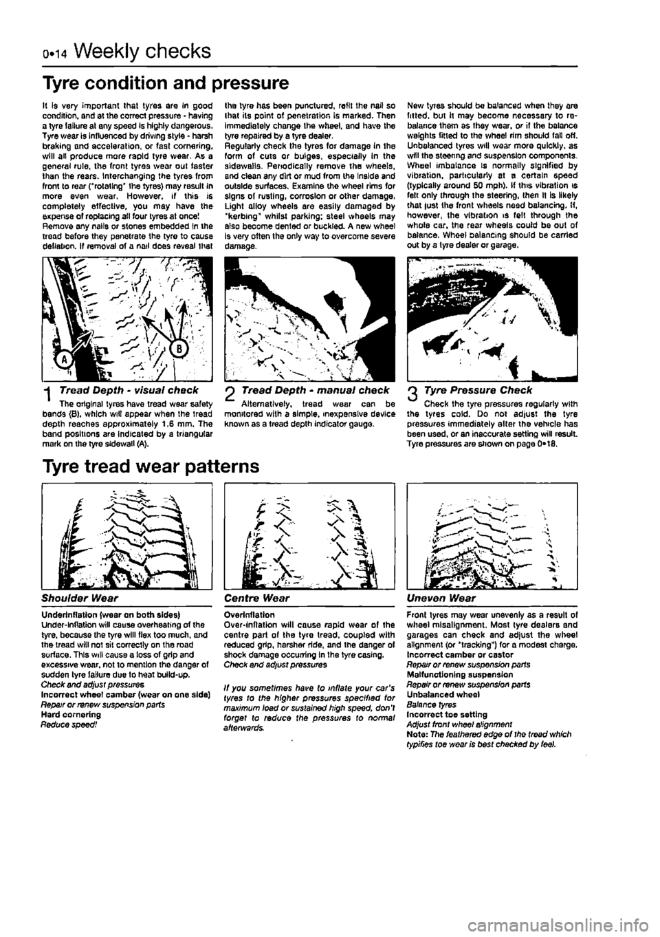
-j Tread Depth • visual check The original tyres have tread wear safety bands {8}, which wiU appear when the tread depth reaches approximately 1.6 mm. The band positions are indicated by a triangular mark on the tyre sidewail (A).
Tyre tread wear patterns
2 Tread Depth * manual check Alternatively, tread wear can be monitored with a simple, inexpensive device known as a tread depth indicator gauge.
2 Tyre Pressure Check Check the tyre pressures regularly with the tyres cold. Do not adjust the tyre pressures immediately alter the vehicle has been used, or an inaccurate setting will result Tyre pressures are shown on page 0*18.
Shoulder Wear Centre Wear Uneven Wear
Underinflatlon {wear an both sides) Under-lnflatton will cause overheating of the tyre, because the tyre will flex too much, and the tread will not sit correctly on the road surface. This will cause a loss of grip and excessive wear, not to mention the danger of sudden tyre failure due to heat build-up. Check and adjust pressures Incorrect wheel camber (wear on one side] Repair or renew suspension parts Hard cornering Reduce speed!
Overinflation Over-inflation will cause rapid wear of the centre part of the tyro tread, coupled with reduced grip, harsher ride, and the danger of shock damage occurring in the tyre casing. Check and adjust pressures
It you sometimes have (o inflate your car's tyres to the higher pressures specified tor maximum load or sustained high speed, don't forget to reduce the pressures to normal afterwards.
Front tyres may wear unevenly as a result of wheel misalignment. Most lyre dealers and garages can check and adjust the wheel alignment (or 'tracking") for a modest charge. Incorrect camber or castor Repair or renew suspension parts Malfunctioning suspension Repair or renew suspension parts Unbalanced wheel Balance tyres Incorrect toe setting Adjust front wheel alignment Note: The feathered edge of I he treed which typifies toe wear is best checked by feel.
Page 17 of 225
o«i6 Weekly checks
Battery
Caution: Before carrying out any work on the vehicle battery, read the precautions given In "Safety first" at the start of this manual. • Make sure thai the battery tray is in good condition, and that the clamp Is tight. Coirosion on the tray, retaining clomp and the battery itself can be removed with a solution of water and baking soda, Thoroughly rinse all cleaned areas with water. Any metal parts damaged by corrosion should be covered with a zinc-based primer, then painted. • Periodically (approximately every three months), check the charge condition of the battery as described In Chapter SA. • If the battery Is flat, and you need to jump start your vehicle, see Roadside Repalrz.
Battery corrosion can be kept to a minimum by applying o layer of petroleum Jelly to the clamps and terminals after they are reconnected
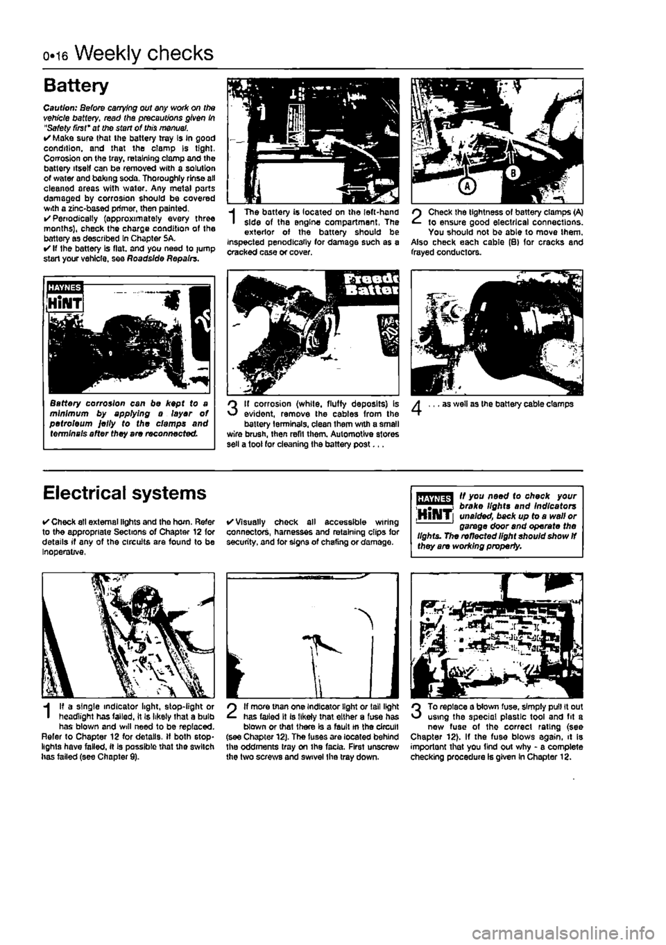
fin %
I
The battery is located on the left-hand side of the engine compartment, The exterior of the battery should be inspected penodlcaily for damage such as a cracked case or cover.
2
Check the tightness of battery clamps (A) to ensure good electrical connections. You should not be able to move them. Also check each cable (B) for cracks and frayed conductors.
3
If corrosion (while, fluffy deposits) is evident, remove the cables from the battery terminals, clean them with a small wire brush, then refit them. Automotive stores sell a tool for cleaning the battery post...
as well as the battery cable clamps
Electrical systems
• Check all external lights and the horn. Refer to the appropriate Sections of Chapter 12 for details if any of the circuits are found to be Inoperative,
• Visually chock all accessible wiring connectors, harnesses and retaining clips for security, and for signs of chafing or damage.
fffjffflg^ " y°u A**^ check your "T™*! broke lights and Indicators ,HllMT[ unaided, back up to a wall or garage door and operate the lights. The reflected light shouid show
If
they are working property.
I
I? a single indicator light, stop-light or headlight has failed, it Is likely that a bulb has blown and will need to be replaced. Refer to Chapter 12 for details. If both stop-lights have failed, it is passible that the switch has failed (see Chapter 9).
2
If more than one Indicator light or tail light has failed It is likely that either a fuse has blown or that there is a fault tn the circuit (see Chapter 12). The fuses are located behind the oddments tray on ihe facia. First unscrew the two screws and swivel Ihe tray down.
3
To replace a blown fuse, simply pull it out using the special plastic tool and fit a new fuse of tho correct rating (see Chapter 12). If the fuse blows again, it is importont that you find out why - a complete checking procedure Is given in Chapter 12.
Page 67 of 225
2B*7 DOHC (16-valve) petrol engine in-car repair procedures
35 Slacken the tensioner pulley retaining nut and reposition the tensioner to align the
mobile
indicator with the fixed reference mark
on the
pulley face (see illustration). Hold the
pdley in
this position and tighten the retaining
nut to the
specified torque. 36 Turn the crankshaft through a further two complete turns In the normal direction of rotation. Check that the timing is correct by alining Ihe piston positioning tools and
camshaft
locking tools as described previously. 37 When all is correct, remove the setting rri
locking
tools and refit the sealing plugs to 1ft© cylinder head extension, using new 0-
nr^s if
necessary. Tighten the plugs securely. 38 Refit the spark plugs as described in Chapter 1A. 39 Refit Ihe ECU and secure with Ihe mooning bolts. 40
Renew the
injector O-ring seals, smear them Kith
8 little
Vaseline then locate the injectors and tef rail onto the inlet manifold lower section.
Saute Ihe fuel rail
with the two retaining bolts. 41 Relit the inlet manifold upper section using new sealing O-rlngs If necessary and
sectre
with the two bolts. 42 Reconnect the wiring connectors for the tot injector harness and the intake air temp-erature/pressure sensor, then connect the fuel pressure regulator vacuum hose and tha
EVAP
purge valve hose. 43 Reconnect the wiring connectors for the ihrottls potentiometer, idle control stepper motor and coolant temperature sensor. Reconnect the brake servo vacuum hose. 44 Refit and adjust the accelerator cable as described in Chapter 4B. 46 Refit the upper and lower timing belt
covers
together with the TDC sensor wiring. 46 Refit the crankshaft pulley and tighten the
three
retaining bolts securely. 47 Refit the air cleaner. Inlet air duct and resonator as described in Chapter 4B. 48
Refit
tha auxiliary drivebelt(s) as described i/t Chapter 1A, then reconnect the battery
S Timing belt tensioner
and
sprockets -
removal
and refitting
Timing
belt tensioner
Removal I
Remove
the timing belt as described in
Section
4. 1 Completely unscrew the tensioner nut and Wiethe tensioner off the mounting stud-Inspection
3 Wipe
the tensioner clean but do not use Kfrents that may contaminate the bearings.
Spin
the tensioner pulley on its hub by hand.
Sfcfl
movement or excessive freeplay is an rcfceticn of severe wear: the tensioner is not 3 serviceable component, and should be nnewsd.
4.33 Holding the camshaft sprocket with the tool described previously while tightening the sprocket bolt Refitting 4 Slide the tensioner pulley over the mounting stud and fit the securing nut. 5 Refit the timing belt as described in Section 4. Camshaft sprocket Removal 6 Remove the timing belt as described in Section 4. 7 Unscrew the bolt and slide the sprocket from the end of the camshaft. Inspection 8 With the sprocket removed, examine the camshaft oil seal for signs of leaking. If necessary, refer to Section 6 and renew it. 9 Check the sprocket teeth for damage. 10 Wipe clean the sprocket and camshaft mating surfaces. Refitting 11 Locate the sprocket on the end of the camshaft, then refit the retaining boll finger tight only at this stage. 12 Refit the timing belt as described in Section 4.
Crankshaft sprocket Removal 13 Remove the timing bell as described In Section 4. 14 Working beneath the engine, unbolt and remove the flywheel lower cover, then hold the flywheel stationary preferably using a tool which engages the flywheel starter ring
<
Alternatively have an assistant engage a wide-bladed screwdriver with the starter ring gear. 15 Unscrew the crankshaft sprocket retaining bolt and slide the sprocket off the end of the crankshaft. The sprocket may have an integral location key on its inner face, or a separate key which locates In a groove in the crankshaft nose may be fitted. Inspection 16 With the sprocket removed, examine the crankshaft oil seal for signs of leaking. If necessary, refer to Section 7 and renew it. 17 Check the sprocket teeth for damage. 18 Wipe clean the sprocket and crankshaft mating surfaces. Refitting 19 Slide the sprocket onto the crankshaft making sure
11
engages the integral key or separate key, then refit the bolt and washer and tighten the bolt to the specified torque while holding the crankshaft stationary using the method described in paragraph 14. 20 Refit the timing belt as described in Section 4.
6 Camshaft
oil
seal -renewal
1 Remove the timing belt and camshaft sprocket as described in Sections 4 and 5. 2 Punch or drill a small hole in the oil seal. Screw a self-tapping screw into the hole, and pull on the screws with pliers to extract the seal. 3 Clean the seal housing, and polish off any burrs or raised edges, which may have caused the seal to fall in the first place. 4 Lubricate the lips of the new seal with clean engine oil, and drive it into position until It seats on its locating shoulder. Use a suitable tubular drift, such as a socket, which bears only on the hard outer edge of the seal. Take care nof to damage the seal lips during fitting. Note that the Seal lips should face inwards. 5 Refit the camshaft sprocket and timing belt as described in Sections 5 and 4.
7 Crankshaft oil seats -renewal I
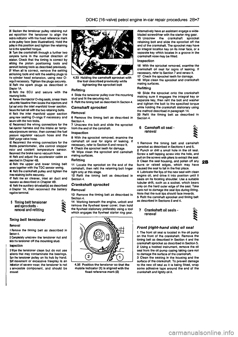
4.35 Position the tensioner so that the mobile Indicator (1) is aligned with the fixed reference mark (2)
Front (right-hand side) oil seal 1 The front oil seal is located in the oil pump on the front of the crankshaft. Remove the timing belt as described in Section 4 and the crankshaft sprocket as described in Section 5. 2 Using a hooked Instrument, remove the oil seal from the oil pump casing taking care not to damage the surface of the crankshaft. 3 Clean the seating in the housing and the surface of the crankshaft. To prevent damage to the new oil seal as it is being fitted, wrap some adhesive tape around the end of the crankshaft and lightly oil it.
Page 95 of 225
2D*10 Engine removal and overhaul procedures
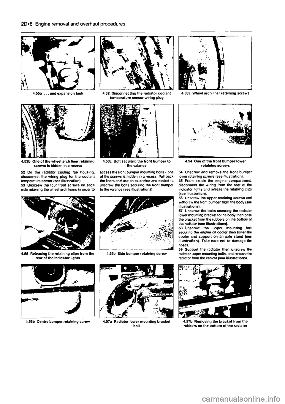
4.50b ... and expansion tank 4.S2 Disconnecting the radiator coolant temperature sensor wiring plug
4.53b One of tho wheel arch liner retaining screws is hidden in a recess 52 On the radiator cooling fan housing, disconnect the wiring plug for tho coolant temperature sensor (see illustration). 53 Unscrew the four front screws on each side retaining the wheel arch liners in order to
4.53c Bolt securing the front bumper to the valance access the front bumper mounting bolts • one of lite screws is hidden in a recess. Pull back the liners and use an extension and socket to unscrew the bolts securing the front bumper to tho valance (see illustrations).
4.55 Releasing the retaining clips from the rear of tho indicator lights 4.56a Side bumper retaining screw
4.56b Centre bumper retaining screw 4.57a Radiator lower mounting bracket bolt
4.54 One of the front bumper lower retaining screws 54 Unscrew and remove the front bumper lower retaining screws (see Illustration). 55 From inside the engine compartment, disconnect the wiring from the rear of the Indicator lights and release the retaining clips (see illustration). 56 Unscrew the upper retaining screws and withdraw the front bumper from the body (see Illustrations). 57 Unscrew the bolts socunng the radiator lower mounting bracket to the body then prise the bracket from the rubbers on the bottom ol the radiator (see Illustrations). 58 Unscrew the upper mounting bolt securing the engine oil cooler then lower the cooler and support on an axle stand (see illustrotion). Take care not to damage the hoses. 59 Support the radiator then unscrew the radiator upper mounting bolts, and remove the radiator from the vehicle (see illustrations).
4.57b Removing the bracket from the rubbers on the bottom of the radiator
Page 102 of 225
2D*10 Engine removal and overhaul procedures
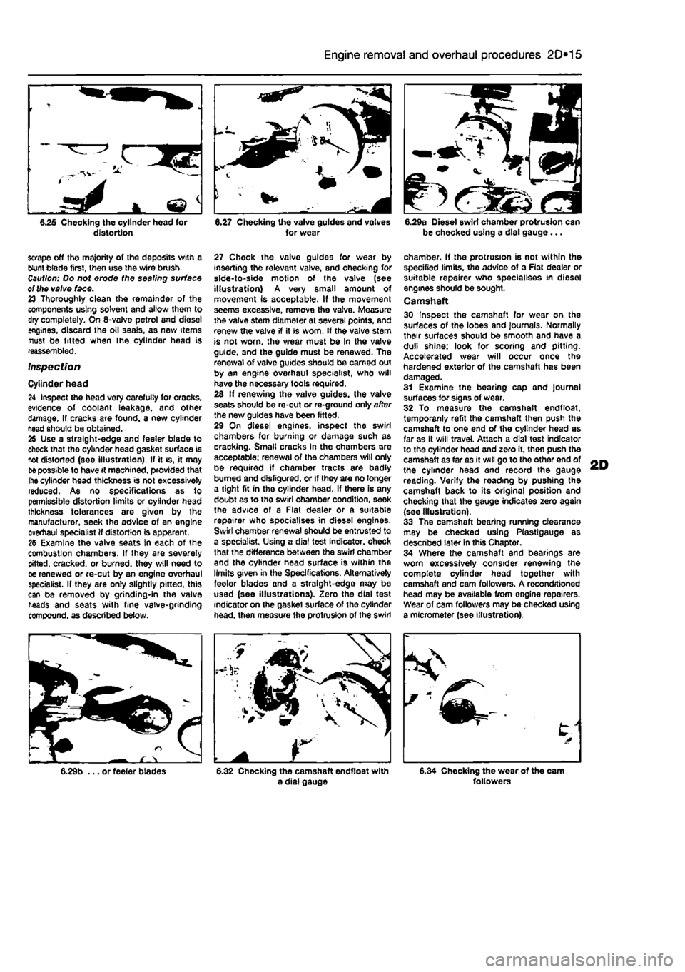
6.25 Checking the cylinder head for distortion 6.27 Checking the valve guides and valves for wear B.29a Diesel swirl chamber protrusion can be checked using a dial gauge...
scrape off the majority of the deposits with a blunt biade first, then use the wire brush. Caution: Do not erode the sealing surface ot the valve face. 23 Thoroughly clean the remainder of the components using solvent and allow them to dry completely. On 6-valve petrol and diesel engines, discard the oil seals, as new items must be fitted when the cylinder head is reassembled.
Inspection
Cylinder head 24 Inspect the head very carelully for cracks, evidence of coolant leakage, and other damage. If cracks are found, a new cylinder head should be obtained. 25 Use a straight-edge and feeler blade to check that the cylinder head gasket surface is not distorted (see illustration). If it is, it may
be
possible to have it machined, provided that Ihe cylinder head thickness is not excessively reduced. As no specifications as to permissible distortion limits or cylinder head thickness tolerances are given by ihe manufacturer, seek the advice of an engine overhaul specialist if distortion Is apparent. 26 Examine the valve seats In each of the combustion chambers, If they are severely pitted, cracked, or burned, they will need to be renewed or re-cut by an engine overhaul specialist. If they are only slightly pitted, this can be removed by grinding-in the valve heads and seats with fine valve-grinding compound, as described below.
27 Check the valve guides for wear by inserting the relevant valve, and checking for side-to-side motion of the valve (see illustration) A very small amount of movement Is acceptable. If the movement seems excessive, remove the valve. Measure the valve stem diameter at several points, and renew the valve if it is worn. If the valve stem is not worn, the wear must be In the valve guide, and the guide must be renewed. The renewal of valve guides should be earned out by an engine overhaul specialist, who will have the necessary tools required. 26 If renewing the vaive guides, the valve seats should be re-cut or re-ground only after the new guides have been fitted. 29 On diesel engines, inspect the swirl chambers for burning or damage such as cracking. Smalt cracks in the chambers are acceptable: renewal of the chambers will only be required if chamber tracts are badly burned and disfigured, or if they are no longer a tight fit in the cylinder head. If there is any doubt as to the swirl chamber condition, seek the advice of a Flat dealer or a suitable repairer who specialises in diesel engines. Swirl chamber renewal should be entrusted to a specialist. Using a dial test indicator, check that the difference between the swirl chamber and the cylinder head surface is within the limits given in Ihe Specifications. Alternatively feeler blades and a straight-edge may bo used (see illustrations). Zero the dial test indicator on the gaskel surface of tho cylinder head, then measure the protrusion of the swirl
chamber, if the protrusion is not within the specified limits, the advice of a Fiat dealer or suitable repairer who specialises in diesel engines should be sought. Camshaft 30 Inspect the camshaft for wear on the surfaces of the lobes and journals. Normally their surfaces should be smooth and have a dull shine: look for scoring and pitting. Accelerated wear will occur once the hardened exterior of the camshaft has been damaged. 31 Examine the bearing cap and journal surfaces for signs of wear. 32 To measure the camshaft endfloat, temporanly refit the camshaft then push the camshaft lo one end of the cylinder head as far as It will travel. Attach a dial test indicator to the cylinder head and zero it, then push the camshaft as far as It will go to the other end of the cylinder head and record the gauge reading. Verify the reading by pushing the camshaft back to its original position and checking that the gauge indicates zero again (see Illustration). 33 The camshaft bearing running clearance may be checked using Plastigauge as described later in this Chapter. 34 Where the camshaft and bearings are worn excessively consider renewing the complete cylinder head together with camshaft and cam followers. A reconditioned head may be available from ongine repairers. Wear of cam followers may be checked using a micrometer (see illustration).
6.29b ... or feeler blades 6.32 Chocking the camshaft endfloat with a dial gauge 6.34 Checking the wear of the cam followers
Page 139 of 225
Fuel system - diesel models 4C*3
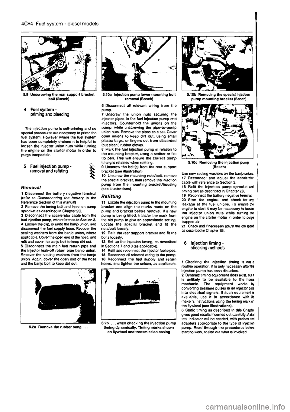
bolt (Bosch)
4 Fuel system -priming and bleeding
The Injection pump Is self-priming and no special procedures are necessary to prime the fuel system. However where the luei system has been completely drained it (s helpful to loosen the injector union nuts while turning the engine on the starter motor In order to purge trooped air.
S Fuel injection pump • removal and refitting 5
Removal 1 Disconnect the battery negative terminal (refer to Disconnecting the battery In the Reference Section of this manual) 2 Remove the timing belt and Injection pump sprocket aa described in Chapter 2C. 3 Disconnect the accelerator cable from the fuel injection pump, with reference to Section 3. 4 Loosen the clip, or undo the banjo union, and disconnect the fuel supply hose. Recover the sealing washers from the banjo union, where applicable. Cover the open end of the hose, and raflt and cover the banjo bolt to keep dirt out. 5 Disconnect the main fuel return pipe and the injector leak-off return pipe banjo union. Recover the sealing washers from the banjo union Again, cover the open end of the hose and the banjo bolt to keep dirt out.
6.2a Remove the rubber bung ...
k
5.10a Injection pump lower mounting bolt removal (Bosch) 6 Disconnect all relevant wiring from the pump. 7 Unscrew the union nuts securing the Injector pipes to the fuel Injection pump and injectors. Counterhold the unions on Ihe pump, while unscrewing the pipe-to-pump union nuts. Remove the pipes as a set. Cover open unions lo keep dirt out. using small plastic begs, or fingers cut from discarded (but clean!) rubber gloves. 8 Mark the fuel Injection pump in relation to the mounting bracket, using a scriber or felt tip pen. This will ensure Ihe correct pump timing is retained when refitting. 9 Unscrew the bolt(s) from Ihe rear support bracket (see illustration) 10 Unscrew the mounting nuts/bolt, remove the special bracket, then remove the injection pump from the mounting bracket/housing (see illustrations).
Refitting 11 Locate the injection pump In the mounting bracket and align the marks mode on the pump and bracket before removal. If a new pump is being fitted, transfer the mark from the old pump to give an approximate setting. Locate the special bracket and fit the nuts/bolt loosely. 12 Refil Ihe rear support bracket and fit the bolts loosely. 13 Set up the injection timing, as described In Sections 7 and 8 (as applicable). 14 Refil and reconnect the injector fuel pipes. 15 Reconnect all relevant wiring to the pump. 16 Reconnect the fuel supply and return hoses, and tighten the unions, as applicable.
6.2b ... when checking the injection pump timing dynamically. Timing marks shown on flywheel and transmission casing
5.10b Removing the special Injection pump mounting brackot (Bosch)
5.10c Removing tho injection pump (Bosch) Use new sealing washers on the banjo unions. 17 Reconnect and adjust the accelerator . cable with reference to Section 3. i 16 Refit the Injection pump sprocket end timing belt as described in Chapter 2C. I 19 Reconnect Ihe battery negative terminal 20 Start the engine, and check for any ' leakage at the fuel unions. To enable the engine to start It may be necessary to loos® the injector union nuts while turning the engine on the starter motor in order to porgt trapped air. 21 Check and if necessary adjust the idle speed as described in Chapter 1B.
6 injection timing -checking methods
1 Checking the injection timing Is not e routlno operation. It Is only necessary aftorth* Injection pump has been disturbed. I 2 Dynamic timing equipment does exist, bulit ' is unlikely to be available to the hame I mechanic. Tho equipment works by I converting pressure pulses in an Injector pips into electrical signals. If such equipment« available, use it In accordance with Its maker's instructions using the liming mark
on
the flywheel (see illustrations). 3 Static timing as described In this Chaptai gives good results If carried out carefully. A dial test indicator will be needed, with probes and adapters appropriate to the typo of infection pump. Read through the procedures beto starting work, to find out what ts Involved.
Page 140 of 225
Fuel system - diesel models
4C*3
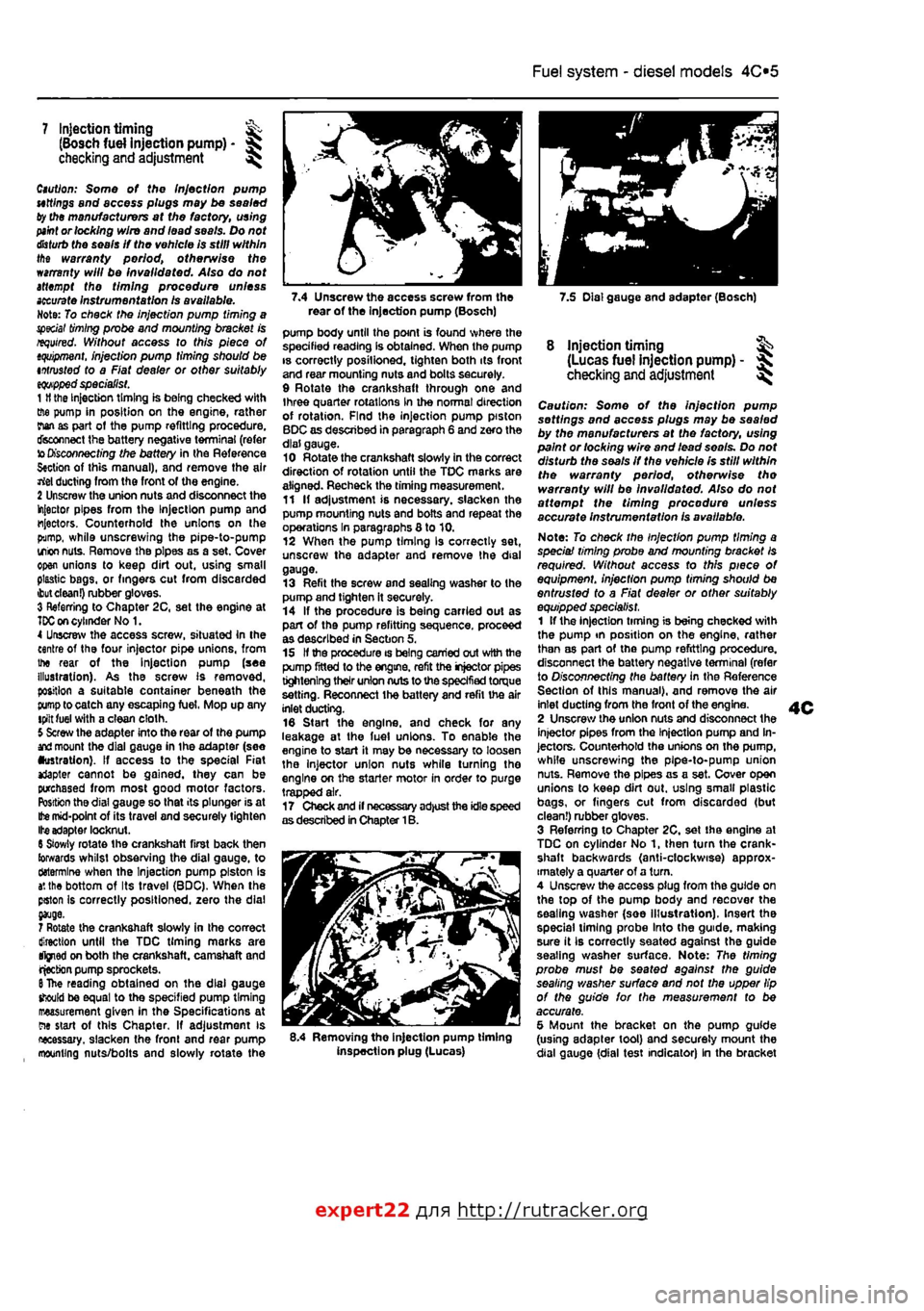
7.4 Unscrew the access screw from the 7.5 Dial gauge and adapter (Bosch) rear of the Injection pump (Bosch)
7 Injection timing ^ (Bosch fuel injection pump) -checking and adjustment ^
Caution: Some of the Injection pump uttlngs and access plugs may be sealed ty the manufacturers at the factory, using
paint
or locking wire and lead seals. Do not
disturb
the seals If the vehicle is still within the warranty period, otherwise the warranty will be invalidated. Also do not attempt the timing procedure unless
accurate
Instrumentation Is available. Note: To check the injection pump timing a special
timing
probe and mounting bracket is required. Without access to this piece of
tquipment.
injection pump timing should be intrusted to a Fiat dealer or other suitably
eqwpped
specialist. 1
H
the Injection timing is being checked with ffie pump in position on the engine, rather rian as part ot the pump refitting procedure, disconnect the battery negative terminal (refer to
Disconnecting
the battery in the Reference S«ction of this manual), and remove the air rtel ducting from the front of the engine. 2 Unscrew the union nuts and disconnect the injector pipes from the Injection pump and injectors. Counterhold the unions on the pump, while unscrewing the pipe-to-pump irion
nuts.
Remove the pipes as a set. Cover open unions to keep dirt out, using small plastic bags, or fingers cut from discarded
ibut clean!)
rubber gloves. 3 Referring to Chapter 2C, set the engine at
TDC on
cylinder No 1. 4 Unscrew the access screw, situated In the centre of the four injector pipe unions, from the rear of the Injection pump (see illustration). As the screw Is removed, position a suitable container beneath the
pump
to catch any escaping fuel, Mop up any tpilt fuel with a clean cloth. 5 Screw the adapter into the rear of the pump
and
mount the dial gauge in ihe adapter (see •ustration). If access to the special Fiat *Japter cannot be gained, they can be purchased from most good motor factors. Position the dial gauge so that its plunger is at
Ifce
mid-point of its travel and securely tighten Ite adapter locknut. 6 Slowly rotate the crankshaft first back then towards whilst observing the dial gauge, to ctotermlne when the Injection pump piston is
a',
the bottom of Its travel (BDC), When the pston Is correctly positioned, zero the dial
7 Rotate the crankshaft slowly in the correct direction until the TDC timing marks are tfjned on both the crankshaft, camshaft and rjecbon pump sprockets.
6
The reading obtained on the dial gauge should be equal to the specified pump timing measurement given in the Specifications at ew start of this Chapter, If adjustment is necessary, slacken the fronl and rear pump mounting nuts/bolts and slowly rotate the
pump body until the point is found where the specified reading Is obtained. When the pump is correctly posilioned, tighten both its front and rear mounting nuts and bolts securely. 9 Rotate the crankshaft through one and three quarter rotations in the normal direction of rotation. Find the injection pump piston BDC as described in paragraph 6 and zero the dial gauge. 10 Rotate the crankshaft slowly in the correct direction of rotation until the TDC marks are aligned. Recheck the timing measurement. 11 If adjustment is necessary, slacken the pump mounting nuts and bolts and repeat the operations In paragraphs 8 to 10. 12 When the pump timing Is correctly set, unscrew the adapter and remove the dial gauge. 13 Refit the screw and sealing washer to the pump and tighten it securely. 14 If the procedure is being carried out as part of the pump refitting sequence, proceed as described in Section 5, 15 If the procedure is being carried out with the pump fitted to the engine, refit the injector pipes tightening their union nuts to the specified torque setting. Reconnect the battery and refit the air inlet ducting. 16 Start the engine, and check for any leakage at the luel unions. To enable the engine to start it may be necessary to loosen the injector union nuts while turning tho engine on the starter motor in order to purge trapped air. 17 Check and if necessary adjust the idle speed as described in Chapter 1B.
8.4 Removing the injection pump timing inspection plug (Lucas)
8 injection timing ^ (Lucas fuel injection pump) - ^ checking
and
adjustment ^
Caution: Some of the injection pump settings and access plugs may be sealed by the manufacturers at the factory, using paint or locking wire and lead seo/s. Do not disturb the seals if the vehicle Is still within the warranty period, otherwise tho warranty will be Invalidated. Also do not affempf the timing procedure unless accurate instrumentation is available.
Note: To check the Injection pump timing a speciai timing probe and mounting bracket Is required. Without access to this piece of equipment, injection pump timing should be entrusted to a Fiat dealer or other suitably equipped specialist. 1 If the injection timing is being checked with the pump tn position on the engine, rather than as part of the pump refitting procedure, disconnect the battery negative terminal (refer to Disconnecting the battery in the Reference Section of this manual), and remove the air inlet ducting from the front of the engine. 2 Unscrew the union nuts and disconnect the injector pipes from the Injection pump and In-jectors. Counterhold the unions on the pump, while unscrewing the pipe-to-pump union nuts. Remove the pipes as a set. Cover open unions to keep dirt out. using smalt plastic bags, or fingers cut from discarded (but clean!) rubber gloves. 3 Referring to Chapter 2C, set the engine at TDC on cylinder No 1, then turn the crank-shaft backwards (anti-clockwise) approx-imately a quarter of a turn. 4 Unscrew the access plug from the guide on the top of the pump body and recover the sealing washer (soe Illustration). Insert the special liming probe Into the guide, making sure it Ib correctly seated against the guide seating washer surface. Note: The timing probe must be seated against the guide sealing washer surface and not the upper lip of the guide for the measurement to be accurate. 5 Mount the bracket on the pump guide (using adapter tool) and securely mount the dial gauge {dial test indicator) In the bracket
expert22 fl/i* http://rutracker.org
Page 149 of 225
5A«2 Starting and charging systems
1 General information and precautions
General information The engine electrical system consists mainly of the charging and starting systems. Because of their engine-related functions, these components are covered separately from the body electrical devices such as the Ilght3, Instalments, etc (which are covered In Chapter 12). On petrol engine models refer to Part B for information on the ignition system, and on diesel models refer to Part C for information on the preheating system. The electncal system Is of 12-volt negative earth type. The battery fitted as original equipment is of maintenance* free (sealed for life} type and Is charged by the alternator, which is belt-driven from the crankshaft pulley. If a non-original battery is fitted It may be of standard or low maintenance type. The starter motor is of the pre-engaged type Incorporating an integral solenoid. On starting, the solenoid moves the drive pinion into engagement with the flywheel ring gear before the starter motor is energised. Once the engine has started, a one-way clutch prevents the motor armature being driven by the engine until the pinion disengages from the flywheel.
Precautions Further details of the various systems are given In the relevant Sections of this Chapter. While some repair procedures are given, the usual course of action is to renew the component concerned. The owner whose interest extends beyond mere component renewal should obtain a copy of the Automobile Electrical & Electronic Systems Manual, available from the publishers of this manual It Is necessary to take extra care when working on the electrical system to avoid damage to semiconductor devices (diodes and transistors), and to avoid the risk of personal injury. In addition to the precautions given in Safety first! at the beginning of this manual, observe the following when working on the system: Always remove rings, watches, etc before working on the electrical system. Even with the battery disconnected, capacitlve discharge could occur If a component's live terminal is earthed through a metal object. This could cause a shock or nasty bum. Do not reverse the battery connections. Components such as the alternator, electronic control units, or any other components having semi-conductor circuitry could be irreparably damaged. If the engine is being started using jump leads and a slave battery, connect the batteries positive-to-posibve and negative-to-
negative (see Jump starting). This also applies when connecting a battery charger but In this case both of the battery terminals should first be disconnected. Never disconnect the battery terminals, the alternator, any electrical wiring or any test Instalments when the engine Is running. Do not allow the engine to turn the alter-nator when the alternator Is not connected. Never test for alternator output by flashing the output lead to earth. Never use an ohmmeter ot the type Incorporating a hand-cranked generator for circuit or continuity testing. Always ensure that the battery negative lead is disconnected when working on the electrical system. Before using electric-arc welding equipment on the car, disconnect the battery, alternator and components such as the fuel Injection/ignition electronic control unit to protect them from the risk of damage. Several systems fitted to the vehicle require battery power to be available at all times, either to ensure their continued operation (such as the clock) or to maintain control unit memories or security codos which would be wiped if the battery were to be disconnected. To ensure that there are no unforeseen consequences of this action. Refer to Disconnecting the battery In the Reference Section of this manual for further Information.
2 Battery- % testing and charging
Standard and tow maintenance battery - testing 1 If the vehicle covers a small annual mileage, it is worthwhile checking the specific gravity of the electrolyte every three months to determine the state of charge of the battery. Use a hydrometer to make the check and compare the results with the following table, Note that the specific gravity readings assume an electrolyte temperature of 15*C (60'F); for every 10*C (18°f) below 158C (60aF) subtract 0.007, For every 108C (16'F) above 15"C (60'F) add 0.007. Ambient temperature Above 26"C Below 25DC Charged 1,210 to 1£30 1,270 to 1.290 70% charged 1.170to1.l90 1.230to1.250 Discharged 1.050toJ.070 1.110 to 1.130 2 If the battery condition is suspect, first check the specific gravity of electrolyte In each cell. A variation of 0.040 or more between any cells indicates loss of electrolyte or deterioration of the internal plates. 3 If the specific gravity variation is 0.040 or more, the battery should be renewed. If the cell variation Is satisfactory but the battery is discharged, it should be charged as described later in this Section.
Maintenance-free battery -testing 4 In cases where a sealed tor life maintenance-free battery is fitted, topplng-up and testing of the electrolyte in each cell Is not possible. The condition of the battery can therefore only be tested using a battery condition Indicator or a voltmeter. 5 Certain models may be fitted with a maintenance-free battery with a built-in charge condition Indicator. The indicator Is located in the top of the battery casing, and indicates the condition of the battery from its colour. If the Indicator shows green, then the battery is In a good state of charge. If the Indicator turns darker, eventually to black, then the battery requires charging, as described later in this Section. If Ihe indicator shows clear/yellow, then the electrolyte level in Ihe battery is too low to allow further use, and tho battery should be renewed. Do not attempt to charge, load or Jump start a battery when the indicator shows dear/yellow. 6 If testing the battery using a voltmeter, connect the voltmeter across the battery and compare the result with those given In the Specifications under 'charge condition'. The test is only accurate if the battery has not been subjected to any kind of charge for the previous six hours. If this is not the esse, switch on the headlights for 30 seconds, then wait four to five minutes baforo testing the battery after switching off the headlights. All other electrical circuits must be switched off, so check that the doors and tailgate are fully shut when making the test, 7 It the voltage reading Is less than 12.2 voHs, then the battery Is discharged, whilst a reading of 12.2 to 12.4 volts indicates 8 partially discharged condition. 6 If the battery Is to be charged, remove It from the vehicle (Section 3) and charge it as described later In this Section.
Standard and low maintenance battery - charging Note: The following is Intended as a guide only. Always refer to the manufacturer's recommendations (often printed on a label attached to the battery) before charging a battery. 9 Charge the battery at a rate of 3.5 to 4 amps and continue to charge the battery at this rate until no further rise In specific gravity Is noted over a four hour period. 10 Alternatively, a trickle charger charging at the rate of 1.5 amps can safely be used overnight. 11 Specially rapid boost charges which are claimed to restore the power of the battery in t to 2 hours are not recommended, as they can cause serious damage to the battery plates through overheating, 12 While charging the battery, note that the temperature of the electrolyte should never exceed 37.8*C(100°F),
Page 165 of 225
7A«4 Manual transmission
33 Remove lha air cleaner front section and air ducting with reference to Chapter 4C. Also disconnect the injection pump vacuum pipe from the clips on the left-hand end of the cylinder head. This work is necessary in order to fit the engine hoist 34 Support the weight of the engine using a hoist attached to the engine lifting eyes, or alternatively use a trolley Jack and block of wood beneath the engine. 35 Unscrew the nuts securing the downpipe to the exhaust manifold, then lower it and support on an axle stand. Recover the gasket. 36 Unscrew the starter motor mounting bolts and support the starter motor to one side. 37 Disconnect the wiring from the reversing light switch on the front of the transmission. 38 Unscrew the nut and disconnect the earth cable from its stud. 39 Trace the wiring back from the electronic speedometer sensor and disconnect the connector located on the left-hand side ot the engine. If a mechanical speedometer Is fitted unscrew the knurled collar and disconnect the cabte from the transmission. 40 Unbolt and remove the transmission lower cover. 41 Using an Allen key unscrew the bolts securing the inner end of the left-hand driveshaft to the transmission flange. Remove the bolts and recover the spacer plates. Support the driveshaft on an axle stand. 42 Unscrew and remove the bolts securing the left-hand swivel hub assembly to the front suspension strut, then separate the components and support the swivel hub on an axle stand. 43 Move the swrvel hub assembly outwards and support the driveshaft away from Ihe transmission. 44 Using an Allen key unscrew the bolts securing the Inner end of the right-hand driveshaft to the intermediate shaft flange. Remove the bolts and recover the spacer plates. Support the driveshaft on an axle stand. 45 Remove the intermediate driveshaft with reference to Chapter 8. 46 Working beneath the vehicle, unscrew the bolts securing the rear engine mounting to the underbody then unscrew the bolts securing the mounting to the transmission and withdraw the mounting assembly from under the vehicle.
47 Unscrew the bolts securing the left-hand engine/transmission mounting to the body then unscrew Ihe bolts from the transmission and remove the mounting. 48 Support the weight of the transmission on a trolley jack then unscrew the remaining nut and bolts from the bellhousing and pull the transmission away from the engine.
A
Warning: Support the trans-mission to ensure that It remains steady o/i the jack head. Keep the transmission level until the Input shaft
1$
fully withdrawn from the clutch friction plate.
Refitting 48 Refitting is a reversal of the removal procedure, but note the following points. a) Appiy a smear* of high-meiting-point grease to the clutch friction piate splines; take care to avoid contaminating the friction surfaces. b) Tighten all bolts to the specified torque. c) Fit new clips to secure the driveshaft gaiters to the transmission output shafts. d) Adjust the clutch cable (where applicable) as described In Chapter 6.
4 Manual transmission overhaul -general Infomtatlon
Overhauling a manual transmission is a difficult and Involved Job for the DIY home mechanic. In addition to dismantling and reassembling many small parts, clearances must be precisely measured and, if necessary, changed by selecting shims and spacers. Internal transmission components are also often difficult to obtain, and in many Instances, extremely expensive. Because of this, If the transmission develops a fault or becomes noisy. Ihe best course of action is to have the unit overhauled by a specialist repairer, or to obtain an exchange reconditioned unit. Nevertheless, it is not impossible for the more experienced mechanic to overhaul the transmission, provided the special tools are available, and the Job is done in a deliberate step-by-step manner, so that nothing is overlooked.
The tools necessary for an overhaul include internal and external clrclip pliers, bearing pullers, a slide hammer, a sat of pin punches, a dial test Indicator, and possibly a hydraulic press. In addition, a large, sturdy workbench 8od a vice will be required. During dismantling o1 the transmission, make careful notes of how each component
1$
fitted, to make reassembly easier and more accurate. Before dismantling the transmission, it will help if you have some idea what area is malfunctioning. Certain problems can be closely related to specific areas In the transmission, which can make component examination and replacement easier. Refer to the Fault Finding Section at the end of this manual for more Information.
5 Reversing light switch -testing, removal and refitting ||
Testing 1 The reversing light circuit is controlled by a plunger-type switch screwed into the front of the transmission casing. If a fault develops, first ensure that Ihe circuit fuse has not blown. 2 To test the switch, disconnect the wiring connector, and use a multimeter (set to the resistance function) or a battery-and-bulb test circuit to check that there is continuity between the switch terminals only when reverse gear is selected. If this is not the case, and there are no obvious breaks or other damage to the wires, the switch is faulty, and must be renewed.
Removal 3 Access to the reversing light switch Is best achieved from under the vehicle. Apply the handbrake then jack up Ihe front of the vehicle and support on axle stands (see Jacking and vehicle support). 4 Disconnect the wiring connector, then unscrew It from the transmission casing.
Refitting 5 Refit the switch and tighten securely. 6 Reconnect the wiring then lower the vehicle to the ground.