boot FIAT PUNTO 1998 176 / 1.G Workshop Manual
[x] Cancel search | Manufacturer: FIAT, Model Year: 1998, Model line: PUNTO, Model: FIAT PUNTO 1998 176 / 1.GPages: 225, PDF Size: 18.54 MB
Page 97 of 225

2D*10 Engine removal and overhaul procedures
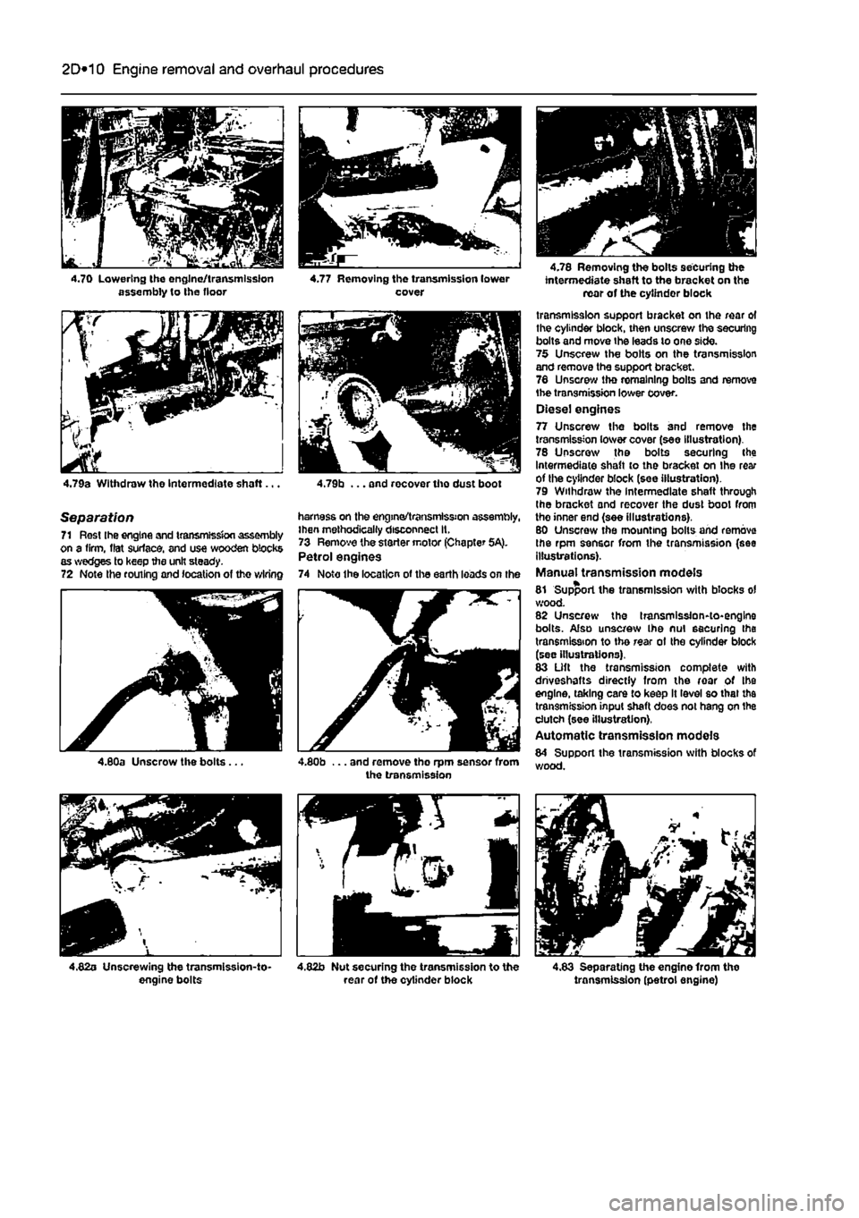
4.70 Lowering the engine/transmission assembly to Ihe floor
4.79a Withdraw the Intermediate shaft...
Separation 71 Rest Ihe engine and transmission assembly on a firm, flat surface, and use wooden blocks as wedges to keep the unit steady. 72 Note the routing and location of the wiring
4.77 Removing the transmission lower cover
4.79b ... and recover the dust boot
harness on the engine/transmission assembly, Ihen methodically disconnect It. 73 Remove the starter motor (Chapter 5A). Petrol engines 74 Noto the location of the earth loads on the
4.78 Removing the bolts securing the intermediate shaft to the bracket on the rear of the cylinder block
transmission support bracket on the rear of the cylinder block, then unscrew the securing bolts and move the leads to one side. 75 Unscrew the bolts on the transmission and remove the support bracket. 78 Unscrew tho remaining bolts and remove the transmission lower cover. Diesel engines 77 Unscrew the bolts and remove the transmission lower cover (see Illustration). 78 Unscrew the bolts securing the Intermediate shaft to the bracket on Ihe rear of the cylinder block (see illustration). 79 Withdraw the Intermediate shaft through the bracket and recover the dust boot from tho inner end (see illustrations). 80 Unscrew the mounting bolts and remove the rpm sensor from the transmission (see illustrations). Manual transmission models 81 Support the transmission with blocks ol wood. 82 Unscrew the transmission-to-engine bolts. Also unscrew Ihe nut securing the transmission to the rear ot the cylinder block (see illustrations). 83 Lift the transmission complete with driveshafts directly from the roar of Ihe engine, taking care to keep It level so that the transmission input shaft does not hang on the clutch (see illustration), Automatic transmission models 84 Support the transmission with blocks of wood.
4.83 Separating the engine from tho transmission (petrol engine)
Page 98 of 225

2D*10 Engine removal and overhaul procedures
05 Remove the brush holder assembly from the automatic transmission as described in Chapter 7B, Section 4. The brushes bear on the slip rings at the rear of the electro-magnetic clutch housing and they may be damaged when the transmission is removed. 86 Unscrew and remove the transmission-to-engine bolts then carefully draw the transmission away from the engine, resting It securely on wooden blocks. Collect the locating dowels If they are loose enough to be extracted, 87 If the oil pump driveshaft remains engaged with the crankshaft, remove it and reert Into the transmission to protect It from damage.
Connection 86 If the engine and transmission have not been separated, go to paragraph 104. Manual transmission models 89 Smear a little high-melting-point grease
on
the splines of the transmission input shaft. Do not use an excessive amount as there Is the risk of contaminating the clutch friction plate. 90 Carefully offer up the transmission to the engine cylinder block, guiding the input shaft through the clutch friction plate. 91 Refit the transmission-to-engine bolts and
the
single nut. hand^jghtenlng 1hem to secure the transmission in position. Note: Do not hghten them to force the engine and transmission together. Ensure that the beilhousing and cylinder block mating faces will butt together evenly without obstruction, before finally tightening the bolts and nut securely. Automatic transmission models 92 Check that the oil pump driveshaft is correctly engaged with the oil pump in the transmission. 93 Carefully offer up the transmission to Ihe rear of the engine and insert the oil pump driveshaft In the centre of the electro-magnetic clutch housing. Locate the transmission on the locating dowels then Insert the bolts and tighten them securely. 94 Refit the brush holder assembly to the automatic transmission with reference to Chapter 7B, Section 4. Petrol engines 96 Refit the transmission lower cover and tighten the bolts. 96 Locate the support bracket on the lower cover, then insert the bolts hand-tight. Also Insert the bolts securing the bracket lo the rear of Ihe cylinder block. With all the bolts Inserted, tighten them securely. 97 Refit the earth leads and tighten the bolts. Diesel engines 98 Refit the rpm sensor and tighten the bolts. 99 Insert the Intermediate shaft through the bracket then locate the dust boot on it and insert the Inner end in the transmission.
100 Refit and tighten the bolts securing the Intermediate shaft to the bracket on the rear of the cylinder block. 101 Refit the transmission lower cover and tighten the bolts. Ail models 102 Refit the starter motor (see Chapter 5A). 103 Refit the wiring harness to the components on the engine/transmission assembly making sure it is routed correctly.
Refitting 104 Locate the engine/transmission assembly beneath the engine compartment and attach the hoist to the lifting eyes. 105 Carefully lift the assembly up into the engine compartment taking care not to damage the surrounding components. 106 Reconnect the left-hand engine/trans-mission mounting to the body and tighten the bolts. 107 Reconnect Ihe right-hand engine mounting to the body and tighten the bolts. 108 Working beneath the vehicle, refit the rear engine mounting and tighten the bolts. 109 Disconnect the hoist from the engine and transmission lifting eyes and remove the hoist from under the vehicle. 110 The remainder of the refitting procedure is the direct reverse of the removal procedure, noting the following points:
a) Ensure that alf sections of the wiring harness follow their original routing; use new cable-ties to secure the harness In position, keeping it away from sources
of
heat and abrasion. b) On vehicles with manual transmission check and if necessary adjust the gearchenge cable and rod with reference to Chapter 7A. c) On vehicles with automatic transmission use new ro//p/ns fo secure the driveshafts to the transmission output stubs. Also check and if necessary adjust the kickdown end selector cables with reference to Chapter 78. d) Ensure that afi hoses are correctly routed and are secured with the correct hose clips, where applicable. If the hose clips cannot be used again; proprietary worm drive clips should be fitted
In
their place. e) Refill the cooling system as described in Chapter 1A or 18. f) Refill the engine with appropriate grades and quantities of oil (Chapter
1A
or 1B). g) Refit and adjust the auxiliary drivebelt(s) wfth reference fo Chapter 1A or 1B. h) Check and If necessary adjust the accelerator cable with reference to Chapter
AA,
48 or
AC.
i) When the engine is started for the first time, check for
air,
coolant, lubricant and fuel leaks from manifolds, hoses etc. If
the
engine has been overhauled, read
the
notes In Section 13 before attempting to starlit.
5 Engine overhaul • dismantling sequence
1 It is much easier to dismantle and work on the engine if it is mounted on a portable engine stand. These stands can often be hired from a tool hire shop. Before the engine is mounted on a stand, the flywheel should be removed, so that the stand bolts can be tightened Into the end of the cylinder block/crankcase. 2 If a stand Is not available, it Is possible to dismantle the engine with it blocked up on a sturdy workbench, or on the floor, Be very careful not to tip or drop the engine when working without a stand. 3 If you intend to obtain a reconditioned engine, all anclllarles must be removed first, to be transferred to the replacement engine (just as they will If you are doing a complete engine overhaul yourself). These components Include the following:
Petroi engines a) Power steering pump if removed with the engine (Chapter
10).
b) Alternator fmcluding mounting brackets) and starter motor (Chapter
SA).
c) The Ignition system and HT components including ail sensors, HT leads and
spark
plugs (Chapters 1A and
SB).
d) The fuel injection system components (Chapters A A and
AB).
e) All electrical switches, actuators and sensors, and the engine wiring harness (Chapters 4A, AB, SB). f) Inlet and exhaust manifolds (Chapters 4A, AB end
AD).
g) Engine oil dipstick and tube. h) Engine mountings (Chapter
2A).
i) Flywheef/driveptate (Chapter
2A).
j) Clutch components (Chapter
6)
- manual transmission. k) Electro-magnetic clutch components (Chapter 7B) - automatic transmission. I) Cooling system components (Chapter
3).
Diesei engines a) Power steering pump //removed with the engine (Chapter
10).
b) Alternator (Including mounting brackets) and starter motor (Chapter 5A). c) The glow plugfpre-heatlng system components (Chapter
SC).
d) Ait fuel system components, including the fuel injection pump, all sensors and actuators (Chapter
AC).
e) The vacuum pump. f) Ail electrical switches, actuators and sensors, and the engine wiring harness (Chapter 4C and 5C). g) Inlet and exhaust manifolds and, where applicable, the turbocharger (Chapter
AC
and 4D). h) The engine oil level dipstick and its tube. i) Engine mountings (Chapter
2C).
Page 194 of 225

Suspension and steering 10*6
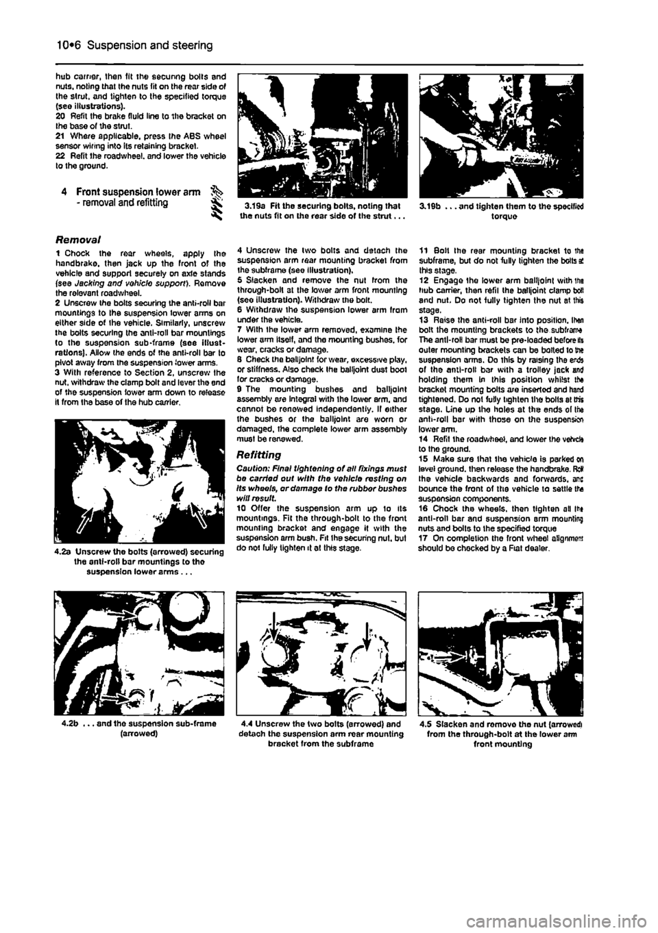
hub earner, then fit the securing bolts and nuts, noting that the nuts fit on the rear side of the strut, and tighten to the specified torque (see illustrations). 20 Refit the brake fluid line to the bracket on Ihe base of the strut. 21 Where applicable, press the ABS wheel sensor winng into its retaining bracket. 22 Refit the roadwheel. and lower the vehicle to the ground.
4 Front suspension lower arm - removal and refitting 3.19a Fit the securing bolts, noting that the nuts fit on the rear side of the strut...
Removal 1 Chock the rear wheels, apply the handbrake, then jack up the front of the vehicle and support securely on axle stands (see Jacking and vehicle support). Remove the relevant roadwheel. 2 Unscrew the bolts securing the anti-roll bar mountings to the suspension lower arms on either side ot Ihe vehicle. Similarly, unscrew the bolts securing the anti-roll bar mountings to the suspension sub-frame (see illust-rations). Allow the ends of the anti-roll bar to pivot away from the suspension lower arms. 3 With reference to Section 2, unscrew Ihe nut. withdraw the clamp bolt and lever the end of the suspension lower arm down to release it from the base of the hub carrier.
4.2s Unscrew the bolts (arrowed) securing the anti-roll bar mountings to tho suspension lower arms...
4 Unscrow the two bolts and detach the suspension arm rear mounting bracket from the subframe (see Illustration). 5 Slacken and remove the nut from the through-bolt at the lower arm front mounting (seo illustration). Withdraw the bolt. 6 Withdraw Ihe suspension lower arm from under the vehicle. 7 With the lower arm removed, examine the lower arm Itself, and the mounting bushes, for wear, cracks or damage. S Check the balljoint for wear, excessive play, or stiffness. Also check Ihe balljoint dust boot for cracks or damage. 9 The mounting bushes and balljoint assembly are integral with the lower arm. and cannot be renewed independently. If either the bushes or the balljoint are worn or damaged, the complete lower arm assembly must be renewed.
Refitting Caution: Final tightening of all fixings must be carried out with the vehicle resting on Its wheels, or damage to the rubbor bushes will result 10 Offer the suspension arm up lo Its mountings. Fit the through-bolt to the front mounting bracket and engage it with the suspension arm bush. Fit Ihe securing nut. but do not fully tighten it at this stage.
. and tho suspension sub-frame (arrowed) 4.4 Unscrew the two bolts (arrowed) and detaoh the suspension arm rear mounting bracket from the subframe
3.19b ... and tighten them to the specified torque
11 Bolt Ihe rear mounting bracket to the subframe, but do not fully tighten the bolts a! this stage, 12 Engage the lower arm balljoint svith ifia hub carrier, then refii the balljoint clamp boll and nut. Do not fully tighten the nut at this stage. 13 Raise the anti-roll bar into position. Itan bolt the mounting brackets to the subfrarra The anti-roll bar must be pre-loaded before lis outer mounting brackets can be bolted to the suspension arms. Do this by raising tha erds of the anti-roll bar with a trolley jack and holding them in this position whilst the bracket mounting bolts are inserted and hand tightened. Do not fully tighten the bolls at trts stage, line up the holes at the ends of the anti-roll bar with those on the suspension lower arm. 14 Refit the roadwheel, and lower the vehrcfe to the ground. 15 Make sure that the vehicle is parked on level ground, then release the handbrake. Red the vehicle backwards and forwards, arc bounce the front of the vehicle to settle the suspension components. 16 Chock the wheels, then tighten all lit* anti-roll bar and suspension arm mounting nuts and bolts to the specified torque 17 On completion the front wheel alignment should be chocked by a Fiat dealer.
4.5 Slacken and romove tho nut (arrowed! from the through-bolt at the lower arm front mounting
Page 216 of 225

Body electrical systems 12*3
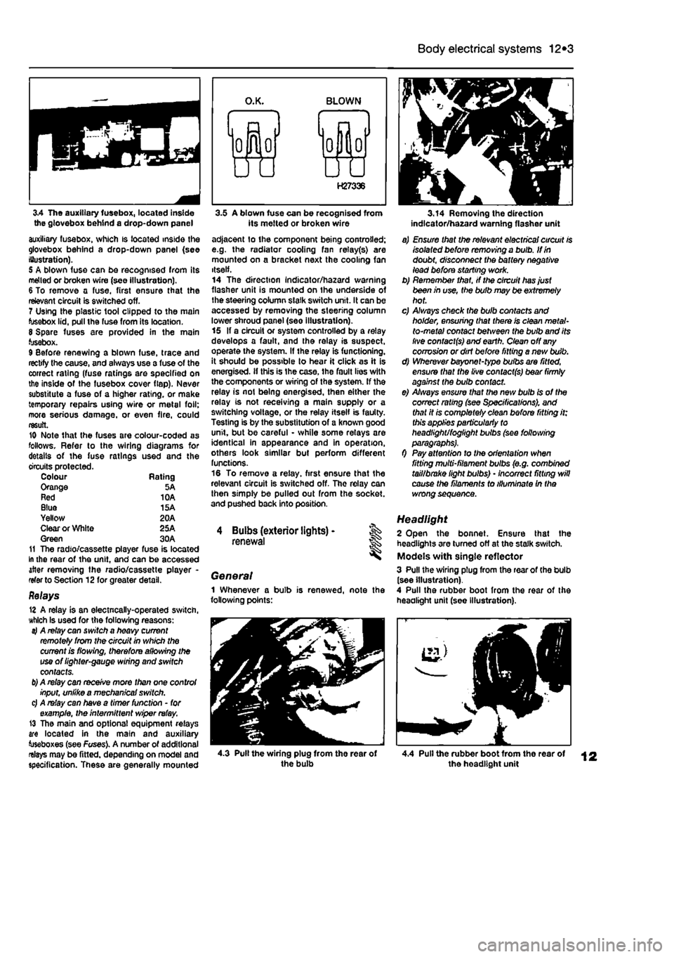
3.4 The auxiliary fusebox, located inside the glovebox behind a drop-down panel auxiliary fusebox, which is located inside the glovebox behind a drop-down panel (see Illustration). 5 A blown fuse can be recognised from its melted or broken wire (see illustration). 6 To remove a fuse, first ensure that the relevant circuit is switched off. 7 Using the plastic tool clipped to the main fusebox lid, pull the fuse from its location. 8 Spare fuses are provided in the main fusebox. 9 Before renewing a blown fuse, trace and rectify the cause, and always use a fuse of the correct rating (fuse ratings are specified on the inside of the fusebox cover flap). Never substitute a fuse of a higher rating, or make temporary repairs using wire or metal foil; more serious damage, or even fire, could result. 10 Note that the fuses are colour-coded as follows. Refer to the wiring diagrams for details of the fuse ratings used and the circuits protected. Colour Rating Orange 5A Red 10A Blue 15A Yellow 20A Clear or White 25A Green 30A 11 The radio/cassette player fuse is located In the rear of the unit, and can be accessed after removing the radio/cassette player -refer to Section 12for greater detail.
Relays 12 A relay is an electncally-operated switch, which Is used for the following reasons: 4 A relay can switch a heavy current remotely from the circuit in which the current is flowing, therefore allowing the use of lighter-gauge wiring and switch contacts.
b)
A relay can receive more than one control input, unlike a mechanical switch. c) A relay can have a timer function - for example, the intermittent wiper relay. 13 The main and optional equipment relays are located in the main and auxiliary toseboxes (see Fuses). A number of additional relays may be fitted, depending on model and specification. These are generally mounted
3.5 A blown fuse can be recognised from its melted or broken wire adjacent lo the component being controlled; e.g. the radiator cooling fan relay(s) are mounted on a bracket next the cooling fan itself. 14 The direction Indicator/hazard warning flasher unit is mounted on the underside of the steering column slalk switch unit. It can be accessed by removing the steering column lower shroud panel (see illustration). 15 If a circuit or system controlled by a relay develops a fault, and the relay is suspect, operate the system. If the relay is functioning, it should be possible to hear it click as it is energised, if this is Ihe case, the fault lies with the components or wiring of the system. If the relay is not being energised, then either the relay is not receiving a main supply or a switching voltage, or the relay itself is faulty. Testing is by the substitution of a known good unit, but be careful - while some relays are identical in appearance and in operation, others look similar but perform different functions. 16 To remove a relay, first ensure that the relevant circuit is switched off. The relay can then simply be pulled out from the socket, and pushed back into position.
4 Buibs (exterior lights) -renewal
General 1 Whenever a bulb is renewed, note the following points:
3.14 Removing the direction indlcator/ha2ard warning flasher unit
a) Ensure that the relevant electrical circuit is isolated before removing a bulb. If in doubt, disconnect the battery negative lead before starting work. b) Remember that, if the circuit has just been in use, the bulb may be extremely hot. c) A/ways check the bulb contacts and holder, ensuring that there is clean metal-to-metal contact between the bulb and its live contacts) and earth. Clean off
any
corrosion or dirt before fitting a nevt bulb. d) Wherever bayonet-type bulbs are fitted, ensure that the live contacts) bear firmly against the bulb contact. e) Always ensure that the new bulb is of the correct rating (see Specifications), and that it is completely clean before fitting it; this applies particularly to headlight/foglight bulbs (see following
0 Pay attention to the orientation when fitting multi-filament bulbs (e.g. combined tail/brake light bulbs) • incorrect fitting will cause the filaments to illuminate In the wrong sequence.
Headlight 2 Open the bonnet. Ensure that the headlights are turned off at the stalk switch. Models with single reflector 3 Pull the wiring plug from the rear of the bulb (see illustration). 4 Pull the rubber boot from the rear of the headlight unit (see Illustration).
4.3 Pull the wiring plug from the rear of the bulb 4.4 Pull the rubber boot from the rear of the headlight unit